manuals.online logo
Brands
  1. Home
  2. •
  3. Brands
  4. •
  5. Pioneer
  6. •
  7. Amplifier
  8. •
  9. Pioneer A-400 User manual

Pioneer A-400 User manual

-.
Operating
STEREO
AMPLIFIER
Instructions
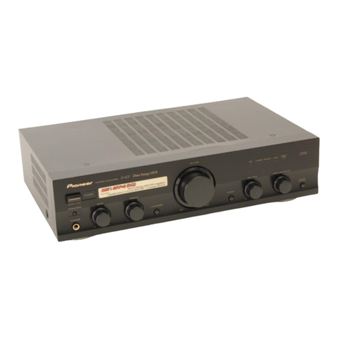
The
illustration
shows
madei
A-400.
Thank
you
for
buying
this
PIONEER
product.
Please
read
through
these
operating
instructions
so
you
will
know
how
to
operate
your
model
properly.
After
you
have
finished
reading
the
instructions,
put
them
away
in
a
safe
place
for
future
reference.
in
some
countries
or
regions,
the
shape
of
the
power
plug
and
power
outlet
may
sometimes
differ
from
that
shown
in
the
explanatory
drawings.
However,
the
method
of
connecting
and
operating
the
unit
is
the
same.
WARNING:
To
prevent
FIRE
OR
SHOCK
HAZARD,
DO
NOT
EXPOSE
THIS
APPLIANCE
TO
RAIN
OR
MOISTURE.
“This
product
complies
with
the
Radio
Interference
require-
ments
of
the
EC
{European
Community)
Directive
87/308/EEC.”
IMPORTANT
1
The
lightning
flash
with
arrowhead,
within
an
equilateral
triangle,
is
intended
to
alert
the
user
of
the
presence
of
uninsulated
“dangerous
voltage”
within
the
product's
enclosure
that
may
be
of
sufficient
magnitude
to
constitute
a
risk
of
electric
shock
to
persons.
CAUTION
RISK
OF
ELECTRIC
SHOCK
Zx,.?
DO
NOT
OPEN.
4
CAUTION:
TO
PREVENT
THE
RISK
OF
ELECTRIC
SHOCK,
DO
NOT
REMOVE
COVER
{OR
BACK}.
NO
USER-
QUALIFIED
SERVICE
PERSONNEL,
The
exclamation
point
within
an
equilateral
triangle
is
intended
to
alert
the
user
of
the
presence
of
important
operating
and
maintenance
(servicing)
instructions
in
the
literature
accompanying
the
appliance.
4
\
SERVICEABLE
PARTS
INSIDE,
REFER
SERVICING
TO.
t
%
%,
IMPORTANT
2
If
the
apparatus
is
fitted
with
AC
mains
power
outlets),
see
REAR
PANEL
FACILITIES
for
convenient
connection
of
additional
Hi-Fi
componentis}.
Make
all
connections
to
the
AC
outlets)
and
the
signal
terminals
first.
Connect
the
plug
to
the
wall
socket
last,
make
sure
that
the
power
switch
is
off.
THIS
APPARATUS
MUST
BE
EARTHED
FOR
USE
IN
THE
UNITED
KINGDOM
‘The
wires
in
this
mains
fead
are
coloured
in
accordance
with
the
following
code:
Green-
and:
Yellow:
Earth
Blu
Neutral
Brown:
Live
As
the
colours
of
the
wires
in
the
mains
iead
of
this
apparatus
may
not
correspond
with
the
coloured
marking
identifying
the
terminals
in
your
plug
proceed
as
follows:
The
wire
whichis
coloured
graen-and-yellow
must
be
connected
(0
the
termina!
in
the
plug
which
is
marked
by
the
letter
E
or
by
the
safety
earth
symbol
+
or
coloured
green
of
green-and-yellow.
‘The
wire
which
is
coloured
biue
must
be
connected
to
the
terminal
which
is
marked
with
the
letter
N
or
coloured
black.
‘The
wire
whichis
coloured
brown
must
be
connected
to
the
terminal
which
is
marked
with
the
letter
L
or
coloured
red.
Equipment
sold
in
the
U.K.
is
not
supplied
with
a
power
Plug.
®
PIONEER’
The
future
of
sound
and
vision.
FEATURES
.....s.cssseesereeeeeeee
2
CONNECTIONS
....
2:
PANEL
FACILITIES
4
CONTENTS
OPERATIONS
.
TROUBLESHOOTING
SPECIFICATIONS...
FEATURES
*
Drive
capacity
85
W
+
85
W/4
Q
(DIN)
matching
to
high
power
and
jow
impedance
type
speaker
system.
[model
A-300
.......e
eeeceerseeeseeeeeeneee
60
W
+
60
W/4
@
{DIN}}
*
The
use
of
a
Super
Linear
Circuit
assures
high
fidelity
playback
of
consistent
frequency
characteristics,
accompanied
by
maximum
clarity.
*
Clean
ground
technology
prevents
noise
on
power
line
to
flow
to
the
signal
ground
line,
permitting
clean
sound
reproduction.
*
REC
selector
switch
makes
tape
editing
very
simple.
CONNECTIONS
*
Comes
with
a
built-in
phono
equalizer
which
accepts
MC
cartridges.
{A-400
only)
*
Honeycomb
Chassis,
Honeycomb
Heat
Sink
(Thorough
anti-vibration
construction).
.
CONNECTING
THE
SPEAKER
CORDS
1.
Strip
off
the
vinyl
covering
and
twist
the
tip
of
the
wire
core.
@
Twist
the
wire
core.
2.
Loosen
the
knob
and
insert
the
wire
core
into
the
terminal
hole.
3.
Tighten
the
knob
to
fix
the
wire
core
in
place.
@ @
o-
4.
E
is
Using
banana
plugs
As
shown
in
the
diagram,
insert
the
plugs
ail
the
way
into
the
holes
in
the
ends
of
the
speaker
terminals.
4,
{Example:
right
channel]
Speaker
cord
NOTE:
Do
not
allow
the
wire
core
to
protrude
and
touch
other
terminals
or
wires.
ff
the
cores
of
differing
wires
touch,
damage
may
be
caused
to
your
amplifier
and/or
speaker
systems.
3
2
<ARBI247>
Speaker
Impedance
The
speaker
systems
are
connected
to
only
SPEAKERS
terminals,
such
speakers
should
have
rated
impedance
in
the
range
of
4
-
16
9.
CONNECTING
THE
Input/Output
CORDS
Connect
the
white
plug
to
the
L
{left}
side,
and
the red
plug
to
the
R
{right}
side,
Be
sure
to
insert
the
plugs
in
securely.
.
Left
channel
White
plug
~~
Right
channel
~~
a
Cite
LEER
Red
plug
The
Input/Output
jacks
of
this unit
are
dull
tinplated,
aiming
at
high
audio
quality.
CONNECTIONS
@
DATCassette
decks
@
CD
player
To
an
AC
walt
socket
@)
Tuner
@
LD
player,
VCR
etc.
©
Turntable
©
Speaker
@.
Speaker
systern
{L)
system
(R}
3
<ARB1247>
PANEL
FACILITIES
[FRONT
PANEL]
The
illustration
shows
mode!
A-400.
@
POWER
switch/indicator
Press
to
turn
power
to
the
unit
on
and
off.
When
the
power
is
on,
the
indicator
lights.
@REC
SELECTOR
switch
When
this
switch
is
set
to
a
position
other
than
SOURCE
or
OFF,
the
equipment
selected
by
REC
SELECTOR
switch
can
be
recorded
from,
irrespective
of
the
settings
of
INPUT
SELECTOR
and
DIRECT
switches.
TUNER:
To
record
from
the
equipment
connected
to
TUNER
terminals.
CD:
:
To
record
from
the
equipment
connected
to
CD
terminals.
OFF:
In
this
position,
nothing
from
the
REC
terminals
of
DAT/TAPE
1
and
TAPE
2
is
output.
Set
to
this
position
when
not
recording;
the
cassette
deck
will
be
disconnected,
improving
sound
quality.
SOURCE:
To
record
from
the
equipment
selected
by
INPUT
SELECTOR
switch.
TAPE
1m
2:
To
record
{copy)
from
the
cassette
deck
of
DAT/TAPE
1
terminals,
to
the
cassette
deck
of
TAPE
2
terminals.
4
k
TAPE
2
®
1:
j
To
record
{copy}
from
the
cassette
deck
of
TARR
2
terminals,
to
the
cassette
deck
of
DAT/TAPE
1
terminals.
*.
@
INPUT
SELECTOR
switch
Use
to
select
the’
playback
source.
LINE:
For
playback
with
a
component
connected
to
LINE
terminal.
TUNER:
For
AM
or
FM
broadcast
reception
with
a
tuner,
PHONO:
For
record
playback
with
a
tumtable.
NOTE;
*
With
the
A-300,
you
can use
an
MM
cartridge
or
a
high-output
MC
cartridge
fover
1
mV).
*
According
to
the
type
of
cartridge
used
with
the
A-400,
you
can
select
MM
or
MC
with
the
PHONO
SELECTOR
switch.
7
Cb:
For
compact
disc
playback
with
a
CD
player.
4
<ARB1247>
DAT/TAPE
1:
For
playback
with
a
cassette
deck
or
digital
audio
tape
deck
connected
to
DAT/TAPE
1
terminals.
TAPE
2:
For
playback
with
a
cassette
deck
connected
to
TAPE
2
terminals.
@®
VOLUME
CONTROL
Use
to
adjust
the
volume
level.
This
volume
knob
consists
of
two
volume
controls.
Because
you
can
adjust
L
fleft)
and
R
(right)
channel
volume
Jevels
independently,
it
also
functions
as
a
balance
control.
{Example}
To
raise
R
(right)
channel
volume
level,
prevent
the
L
knob
from
tuming
with
one
hand,
and
turn
the
fe
R
knob
with
the
other
hand.
R
L
©®PHONO
SELECTOR
switch
(A-400
only)
Set
in
accordance
with
the
type
of
cartridge
used
with
your
turntable.
MM
(
HL):
Set
to
this
position
when
using
a
moving
magnet
cartridge,.or
a
moving
coil
cartridge
with
a
high
output
of
1
mV
or
more.
MC
{
o=
}:
Set
to
this
position
when
using
a
moving
coil
cartridge.
©
PHONES
jack
When
using
headphones,
insert
the
plug
inta
this
jack.
The
output
to
the
speakers
is
cut
automatically
when
connecting
headphones.
PANEL
FACILITIES
{REAR
PANEL]
(fot
‘OOOO
OO
|
©
©Q'O
©!}©
©
fn
An
coed
curred
PF
eres,
_
[if
®
©)
@
PHONO
terminals
@
TAPE
2
PLAY
terminals
LINE
terminals
@®
TAPE
2
REC
terminals
@DAT/TAPE
1
REC
terminals
:
--
-
CD
terminals
DAT/TAPE
1
PLAY
terminals
@
TUNER
terminals
@
Power
cord
@®
Turntable
ground
terminal
(GND)
Connect
this
cord
to
an
AC
wail
socket,
or
the
AC
outlet
of
an
audio
timer,
:
@
SPEAKERS
terminals
L
(left
channel)
@
SPEAKERS
terminals
R
(right
channel)
5
<ARB1247>
OPERATIONS
PLAYBACK
PROCEDURES
1.
Set
INPUT
SELECTOR
switch
@
to
the
desired
playback
source.
©
For
playback
with
the
equipment
connected
to
LINE
terminals:
Set
to
[LINE].
*
For
reception
of
an
AM/FM
broadcast:
Set
to
[TUNER].
¢
For
playback
of
a
record:
Set
to
[PHONO].
Set
PHONO
SELECTOR
switch
©
to
MM
(3L}or
MC
(=)
according
to
the
type
of
cartridge
being
used.
(A-400
only}
*
For
playback
of
a
compact
disc:
Set
to
[CD].
*
For
playback
of
a
tape:
Set
to
[DAT/TAPE
1]
or
[TAPE
2].
2.
Operate
the
equipment
to
begin
playback.
:
3.
Adjust
playback
volume
with
VOLUME
CONTROL
@)
on
this
unit.
RECORDING
TAPES
1.
Select
the
recording
equipment
with
REC
SELECTOR
switch
@).
*
When
set
to
SOURCE,
the
signals
from
the
device
connected
to
the
terminals
of
the
selected
input
are
recorded.
(To
record
signals
from
the
device
connected
to
PHONO
or
LINE
terminals,
for
instance
set
REC
SELECTOR
switch
to
SOURCE
and
set
INPUT
SELECTOR
switch
to
PHONO
or
LINE
accordingly.)
*
Recording
is
impossible
when
the
switch
is
set
to
OFF.
NOTE:
When
REC
SELECTOR
switch
is
set
to
a
position
other
than
SOURCE
or
OFF,
the
equipment
selected
by
REC
SELECTOR
switch
can
be
recorded
from,
irrespective
of
the
settings
of
INPUT
SELECTOR
switch.
2.
Begin
recording
by
operating
the
recording
equipment.
Refer
to
the
operating
instructions
for
your
cassette
deck
for
proper
operating
procedures.
MONITOR
WHILE
OPERATING
On
a
3-head
cassette
deck,
sound
can
be
concurrently
heard
recording
on
cassette,
This
operation
of
checking
the
sound
quality
and
recording
level
is
called
“‘monitoring.””
For
monitoring,
INPUT
SELECTOR
switch
of
this
unit
must
be
set
to
the
cassette
deck
‘on
which
recording
is
being
done.
\
When
recording
with
the
cassette
deck
eohnected
to
DAT/TAPE
14
‘terminals:
Set
to
DAT/TAPE
1.
©
When
recording
with
the
cassette
deck
Sqqnected
to
TAPE
2
terminals:
Set
to
TAPE
2.
Te
NOTE:
When
recording
trom
PHONO
or
LINE
source,
recording
monitor
is
not
possible,
6
<ARB1247>
COPYING
TAPES
When
two
decks
are
used
{or
when
using
double
cassette
deck),
you
can
record
the
sounds
from
one
deck
onto
the
other.
Application
examples:
*
To
make
a
tape
capy
with
contents
identical
to
the
original
tape.
*
To
edit
a
recording
of
an
FM
broadcast
in
order
to
cut
out
unwanted
commercials,
recording
only
desired
material
onto
another
tape.
When
using
two
cassette
decks
1.
Load
tapes
for
playback
(pre-recorded
tape)
and
recording
(blank
tape)
into
the
respective
cassette
decks.
2.
Select
the
copying
direction
with
REC
SELECTOR
switch
@.
*
When
copying
from
the
cassette
deck
of
DAT/TAPE
1
terminals
to
the
cassette
deck
of
TAPE
2
terminals:
Set
to
TAPE
1
»
2.
*
When
copying
from
the
cassette
deck
of
TAPE
2
terminals
to
the
cassette
deck
of
DAT/TAPE
1
terminals:
Set
to
TAPE
2
1.
NOTE:
The
tape
input
selected
with
REC
SELECTOR
switch
can
be
copied,
regardless
of
the
settings
of
INPUT
SELECTOR.
3.
Operate
the
cassette
decks
ta
begin
copying.
Set
the
cassette
deck
with
the
original
(playback)
tape
to
the
playback
mode,
and
set
the
cassette
deck
with
the
bland
tape
to
the
recording
mode.
TROUBLESHOOTING
:
Incorrect
operations
are
often
mistaken
for
trouble
and
maifunctions.
If
you
think
that
there
is
something
wrong
with
this
component,
check
the
points
below.
Sometimes
the
trouble
may
lie
in
another
component.
Investigate
the
other
components
and
electrical
appliances
being
used.
If
the
trouble
cannot
be
rectified
even
after
exercising
the
checks
listed
below,
ask
your
nearest
PIONEER
authorized
service
center
or
your
dealer
to
carry
out
repair
work.
Symptom
Cause
Remedy
No
power
suppiied
to
unit
*
Power
plug
is
disconnected
from
outiet.
*
The
component
power
plug
has
been
plugged
intol
another
component
power
outlet
{e.g.
timer,
etc.}
but
power
to
that
unit
is
disconnected.
*
Insert
plug
securely
into
outlet.
*
Turn
on
power
to
the
other
component.
No
sound
*
Connecting
cords
are
disconnected
from
terminalis,
or
connected
incorrectly.
*
Terminals,
or
connecting
cords
pin
plugs
are
dirty.
*
INPUT
SELECTOR
switch
is
not
set
to
the
desired
*
Connect
securely.
*
Clean
terminals
and
plugs.
*
Set
the
switch
correctly
(PHONO,
TUNER,
CO,
input
source.
©
Operation
of
other
components
is
incorrect.
LINE,
DAT/TAPE
1,
TAPE
2}.
*
Consult
the
operating
instructions
for
the
other
_|__
components.
No
sound
from
one
speaker
disconnected
on
that
side.
Can’‘t
record
tapes
*
Connections
are
incorrect.
*
Connecting
cords
or
speaker
cords
are
*
The
position
of
REC
SELECTOR
switch
is
incorrect.
|
*
Set
switch
correctly
(See
section
RECORDING
*
Operation
of
cassettte
deck
is
incorrect.
Can't
perform
tape
copying
LOCATION
Install
the
amplifier
in
a
well
ventilated
location
where
it
will
not
be
exposed
to
high
temperature
or
humidity.
Do
not
install
the
arnplifier
in
a
location
which
is
exposed
to
direct
rays
of
the
sun,
or
near
to
hot
appliances
or
radiators.
Excessive
heat
can
adversely
affect
the
cabinet
and
internal
components.
Installation
of
the
amplifier
in
a
damp
or
dusty
environment
may
result
in
malfunction
or
accident.
(Also
avoid
installation
near
cookers
etc.,
where
the
amplifier
may
be
exposed
to
smoke
from
oil,
steam
or
heat.)
POWER-CORD
CAUTION
Xe:
Handle
the
power
cord
by
the
plug.
Do
not
pull
out
the
plug
by
tugging
the
cord
and
never
touch
the
power
cord
when
your
hands
are
wet
as
this
could
cause
a
short
circuit
or
electric
shock.
Do
not
place
the
unit,
a
piece
of
furniture,
etc,.
on
the
power
card,
or
pinch
the
cord.
Never
make
a
knot
in
the
cord
or
tie
it
with
other
cords.
The
power
cords
should
be
routed
such
that
they
are
not
likely
to
be
stepped
on.
A
darnaged
power
cord
can
cause
fire
or
give
you
an
electrical
shock.
Check
the
power
cord
once
in
a
while.
When
you
find
it
damaged,
ask
your
nearest
PIONEER
authorized
service
center
or
your
dealer
for
a
replacement.
*
The
position
of
REC
SELECTOR
switch
is
incorrect.
|
*
Set
switch
correctly
(See
section
COPYING
*
Operation
of
cassettte
deck
is
incorrect.
*
Connect
securely.
TAPES).
*
Reconnect
properly.
*
Consult
the
operating
instructions
for
the
cassette
deck.
TAPES).
*
Consult
the
operating
instructions
for
the
cassette
deck,
MAINTENANCE
OF
EXTERNAL
SURFACES
¢
Use
2
polishing
cloth
or
dry
cloth
to
wipe
off
dust
and
dirt.
*
When
the
surfaces
are
very
dirty,
wipe
with
a
soft
cloth
dipped
in
some
neutral
cleanser
diluted
five
or
six
times
with
water,
and
wrung
out
weil,
and
then
wipe
again
witha
dry
cloth.
Do
not
use
furniture
wax
or
cleaners.
:
*
Never
use
thinners,
benzine,
insecticide
sprays
and
other
chemicals
on
or
near
this
unit,
since
these
will
corrode
the
surfaces.
7
<ARB1247>
SPECIFICATIONS
[A-400]
Amplifier
Section
Continuous
power
outpe
T.H.D.
0.03
%,
82
..
SOW
+
SOW
T.H.D.
0.05
%,
42..
7OW
+
7OW
DIN
Continuous
power
output
{both
channels
driven
at
1
kHz)
PH:De-
1.0%,
8:0
sc
nctesicssccvtanssesseaterns
6OW
+
60W
T.H.D.
1.0
%,
49
.
BW
+
85
Ww
Dynamic
power
output
{on
EIA
dynamic
test
signal}
8
0/4
9/29
..
70
W/100
W/135
W
Total
harmonic
distortion
*
20
Hz
to
20
kHz,
50
W,
82...
20
Hz
to
20
kHz,
70
W,
82
Input
sensitivity/impedance
PHONO
(MM)
PHONO
(MC}..
CO,
TUNER,
LINE,
TAPE
PHONO
overload
level
1
kHz,
T.H.D.
0.008
%
(MM/MC)
........cceceeeeeee
150
mV/12
mV
Output
levelfmpedance
TAPE
REC...
cece
yseisaneceeeeas
Frequency
response
PHONO
(MM).
{both
channels
dri
20
Hz
to
20
kHzj*
2.5
mV/50
k2
0.2
mV/100
2
150
mV/50
ko
w+.
150
mV/2.2
kQ
20
Hz
to
20
kHz,
+
0.3
dB
PHONO
{MC)...
20
Hz
to
20
kHz,
+
0.5
4B
CD,
TUNER,
LINE,
TAPE
5
Hz
to
100
kHz,
*$
dB
Signal-to-Noise
ratio
(IHF
short
circuit,
A
network}
PHONO
(MM,
2.5
mV
input/MC,
0.2
mV
input}
.
87
dB/69
dB
CO,
TUNER,
LINE,
TAPE
108
4B
Signal-to-Noise
ratio
(DIN,
continuous
power/50
mW}
PHONO
(MM)...
-
74
d8/63
dB
CD,
TUNER,
LINE,
TAPE.
.
88
dB/65
4B
Power
Supply/Miscellaneous
Power
requirements
........c:ccceeeeeee
ais
cig
a.c.
240
V
~,
50/60
Hz
Power
consumption
steeeeereceereee
SZO
W
Dimensions
..........
420
(W}
x
352
(D}
x
126
({H)
mm
Weight
(without
package)
..
w-
8.0
kg
Accessories
Operating
instructions
.......scsccsscesecseessecceeee
sdodesaastcasdbsearde
odes:
1
*
Specificatios
and
design
subject
to
possible
modification
without
notice,
due
to
improvements.
*
Measured
by
Audio
Spectrum
Analyzer.
{A-300]
Amplifier
Section
Continuous
power
output
(both
channels
driven
at
20
Hz
to
20
kHz}*
T.H.D.
0.03
%,
82.
«
30W
+
30W
T.H.D.
0.05
%,
42.
~40W
+
40W
DIN
Continuous
power
output
(both
channels
driven
at
1
kHz}
THD.
1.0%,
82.
-40W
+
40W
THD,
1.0%,
49.
-
GOW
+
6OW
Dynamic
power
output
{on
EIA
dynamic
test
Signal}
BUG
Gl2
Diss...
ceccsancinctis
che
cassasscitsve
cece.
50
W/75
W/S0
W
20
Hz
te
20
kHz,
40
W,
82...
0.03
%
20
Hz
to
20
kHz,
50
W,
82...
0.05
%
input
sensitivity/impedance
PHONO
(MM)
--
2.5
mV/50
kQ
CD,
TUNER,
LINE;
TAPE
PHONO
overload
level
THz,
THD.
0.02
%
(MM)
...csecccsscsscesesetecescersceosecece
150
mv
Output
level/impedance
TAPE
REC...
150
mV/2.2
kQ
Frequency
response
PHONO
(MM)
20
Hz
to
20
kHz,
+
0.3
dB
--
5
Hz
to
100
kHz,
29
4B
Signal-to-Noise
ratio
(IHF
short
circuit,
A
network)
PHONO
(MM,
2.5
mV
input)
wae
83.
dB
CO,
TUNER,
LINE,
TAPE...
+.
108
dB
Signal-to-Noise
ratio
(DIN,
continuous
power/50
mW)
PHONO
(MM)
+
73
dB/63
dB
CO,
TUNER,
LINE,
TAPE
++
88
dB/65 dB
Power
Supply/Miscellaneous
Power
requirements
.......cccsesssescssceeareae
B.C,
240
V
~,
50/60
Hz
Power
consumption
e
srnecerensccrne
410
W
Dimensions
.........
420
(W)
x
352
(D)
x
126
(H)
mm
Weight
(without
package)
sreseseresee
68
kg
Accessories
Operating
instructions
.........c0.
aabosed
meodensiscca
eddevekagebcccs’
ntecetatec
d
*
Specificatios
and
design
subject
to
possible
modification
without
Notice,
due
to
improvements.
*
Measured
by
Audio
Spectrum
Analyzer.
Published
by
Pioneer
Electronic
Corporation.
Copyright
©
1890
Pioneer
Electronic
Corporation.
All
rights
reserved.
PIONEER
ELECTRONIC
CORPORATION
4-3,
Meguro
1-Chome,
Meguro-ku,
Tokyo
153,
Japan
PIONEER
ELECTRONICS
[USA]
INC.
.
2265
East
220th
Street,
Long
Beach,
California
$0810,
U.S.A.
P.O.
BOX
1720,
Long
Beach,
California
$0801,
U.S.A.
PIONEER
ELECTRONICS
OF
CANADA,
INC.
505
Cochrane
Drive,
Markham,
Ontario
L3R
8E3,
Canada
PIONEER
ELECTRONIC
[EUROPE]N.V.
Keetberglaan
1,
2740
Beveren,
Beigium,
TEL:
03/750.05.11
PIONEER
ELECTRONICS
AUSTRALIAPTY.LTD.
178-184
Boundary
Road,
Braeside,
Victoria
3195,
Australia,
TEL:
[03]
580-9911
<9
7
DOSFF2EOQ9>
Printed
in
Japan
<ARB1247-A>

This manual suits for next models

1

Other Pioneer Amplifier manuals

Pioneer SA-9500II User manual

Pioneer

Pioneer SA-9500II User manual

Pioneer GM-3200T User manual

Pioneer

Pioneer GM-3200T User manual

Pioneer SA-7800 User manual

Pioneer

Pioneer SA-7800 User manual

Pioneer SA-1520 User manual

Pioneer

Pioneer SA-1520 User manual

Pioneer A-229 User manual

Pioneer

Pioneer A-229 User manual

Pioneer GM-X404 User manual

Pioneer

Pioneer GM-X404 User manual

Pioneer GM-7150M User manual

Pioneer

Pioneer GM-7150M User manual

Pioneer GM-222 User manual

Pioneer

Pioneer GM-222 User manual

Pioneer A-40AE User manual

Pioneer

Pioneer A-40AE User manual

Pioneer PRS-D4200F - Premier Amplifier User manual

Pioneer

Pioneer PRS-D4200F - Premier Amplifier User manual

Pioneer A-A6-J User manual

Pioneer

Pioneer A-A6-J User manual

Pioneer GM-4000F User manual

Pioneer

Pioneer GM-4000F User manual

Pioneer GM-A6704/XEUC User manual

Pioneer

Pioneer GM-A6704/XEUC User manual

Pioneer GM-X642 User manual

Pioneer

Pioneer GM-X642 User manual

Pioneer GM-3500T User manual

Pioneer

Pioneer GM-3500T User manual

Pioneer SA-6500 II User manual

Pioneer

Pioneer SA-6500 II User manual

Pioneer GM-D8701 User manual

Pioneer

Pioneer GM-D8701 User manual

Pioneer SA-608 User manual

Pioneer

Pioneer SA-608 User manual

Pioneer A-09 User manual

Pioneer

Pioneer A-09 User manual

Pioneer SR-9 User manual

Pioneer

Pioneer SR-9 User manual

Pioneer PRS-D1200M SERIES User manual

Pioneer

Pioneer PRS-D1200M SERIES User manual

Pioneer GM-X354 User manual

Pioneer

Pioneer GM-X354 User manual

Pioneer A-8 User manual

Pioneer

Pioneer A-8 User manual

Pioneer A-445 User manual

Pioneer

Pioneer A-445 User manual

Popular Amplifier manuals by other brands

Ibanez Sound Wave 20 owner's manual

Ibanez

Ibanez Sound Wave 20 owner's manual

Manta AV-500 user manual

Manta

Manta AV-500 user manual

Ross openGear SRA-8201 user manual

Ross

Ross openGear SRA-8201 user manual

Classe Audio CP-47.5 owner's manual

Classe Audio

Classe Audio CP-47.5 owner's manual

Opera Audio M100S plus user guide

Opera Audio

Opera Audio M100S plus user guide

ARX EarDriver owner's manual

ARX

ARX EarDriver owner's manual

Sonogy Concerto owner's manual

Sonogy

Sonogy Concerto owner's manual

StetSom HIGH LINE 1200.4 user manual

StetSom

StetSom HIGH LINE 1200.4 user manual

Emotiva RSP-1 user guide

Emotiva

Emotiva RSP-1 user guide

PROPHON P4700 quick guide

PROPHON

PROPHON P4700 quick guide

Pd PDV120ZMP3 instruction manual

Pd

Pd PDV120ZMP3 instruction manual

Ceriatone Chupacabra HRP Series user manual

Ceriatone

Ceriatone Chupacabra HRP Series user manual

McIntosh C220 owner's manual

McIntosh

McIntosh C220 owner's manual

ESX Q752 owner's manual

ESX

ESX Q752 owner's manual

Oracle Audio Temple PH 1000 owner's manual

Oracle Audio

Oracle Audio Temple PH 1000 owner's manual

HELIX PP20 DSP manual

HELIX

HELIX PP20 DSP manual

Kenwood KA-7300 Service manual

Kenwood

Kenwood KA-7300 Service manual

Listen Technologies External Microphone Control RS232 Protocol DCS... brochure

Listen Technologies

Listen Technologies External Microphone Control RS232 Protocol DCS... brochure

manuals.online logo
manuals.online logoBrands
  • About & Mission
  • Contact us
  • Privacy Policy
  • Terms and Conditions

Copyright 2025 Manuals.Online. All Rights Reserved.