Audiospektri Guitar Analyser User manual

Guitar Analyser Manual
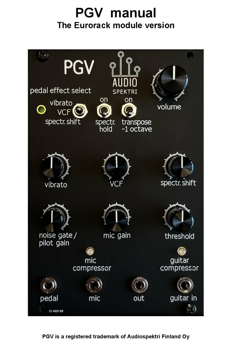
The Guitar Analyser Eurorack module does a full analysis of the signal of a typical six string guitar.
It measures the individual pitch frequency and amplitude of each of the strings. The results of the
analysis are output from the 3.5mm acks of the module. Additionally, the module has several
effects that can be activated to the synthetic signals using the analysis results. The module can be
used as an input interface to bring the guitar signal to a Eurorack system, or as a stand alone guitar
synthesizer generating signals that are impossible to create using typical filtering based modules. It
is 95.5mm wide, occupies 19 HP units.

1
Inputs guitar in: ¼” ack for connecting the guitar. Use the neck microphone of the guitar;
typically a humbucker mic is more reliable in the note detection than a single coil.
pedal: ¼” ack for guitar effect pedal input. The special effects are ad usted
either by a pedal or the front panel “effect ad ust” potentiometer. The pedal is only
activated if it is connected to the module when power is switched on, and the pedal
position is not at zero voltage. Use a pedal that has the output voltage coming from
the tip of the TRS plug. The module feeds its voltage to the ring electrode of the
pedal potentiometer. E.g. the M-Audio effect pedal works when its select switch is
in the “M-Audio” -position.
Outputs Left: six 3.5mm output acks for the measured pitch in the 1V/octave format
(default), or alternatively umper selectable linear voltage output option. The range is
adopted to the guitar frequency scale, so that in the 1V/octave case the note C3
(130.81Hz) corresponds to 1Volt, and the lowest 0.167 Volts corresponds to a drop-
D2 tuned pitch. The maximum 4.8Volts corresponds to the 22nd fret D6 (1174.7Hz).
In the linear scale setting, C3 stays at 1V, but then C2 is 0.5V, C4 is 2V, and C5 is
4V. The maximum voltage 4.8V is reached a little above D#5, and the notes
above that will saturate the output. This is because the D/A converter has 12bit
resolution, and a wider span would have resulted too coarse resolution at the low
pitch end. Now it is relatively decent 3 cents. The advantage of the linear scale is the
fact that linear VCO oscillators are much simpler and cheaper than log scale
ones, single chip ones are easy to build even by a beginner hobbyist.
Right: Six 3.5mm output acks for the synthetic signals that follow the
amplitude and pitch of the analysed separate strings (default), or alternatively the
string amplitudes only, when the effect ad ust potentiometer is at its maximum
position. They are DC connected, with a 2.4V offset; therefore the outputs can be
used for modulating other modules that need a positive control voltage between 0
and 4.8 volts.
One 3.5mm ack “out” for composite signal, i.e. all the six synthetic signals summed
together. it is an AC connected low power output to be connected to a power
amplifier input or to the inputs of other modules.
Po er The module uses only the +12V and GND connections of the Eurorack bus, the
current consumption is 150mA maximum.
Controls pedal effect select: A three position switch that applies the special effect shown at
the right side of the switch individually to each of the synthetic signals that are
generated based on the analysis results of the guitar signal. The base signal is pure
sinewave. See later sections for detailed description of the available effects.
channel allocation method: A three position switch that determines how the
analysis results are output to the six left and right side 3.5mm acks. See a later
section for detailed description of the available methods.
effect hold: A two position switch that in the “on” position allows stacking of the
effects, i.e. when switching from one effect to another, the remaining controls of the
previous effects at the switching moment are left as they were. Keep it in the “off”
position for outputting of the current effect only.

2
compressor gain: A potentiometer that determines the string signals’ gain before the
limiting compressor. If the gain is ad usted high, the signals are limited to constant
maximum amplitude even at a low input picking strength. This control is essential
when one desires to get dynamically evolving output signals, since the FM and
distortion effects are controlled also by the string amplitudes. Each string has a green
led next to its output showing when the corresponding string has reached the limiting
amplitude that also limits the amplitude dependent effect. So, in order to keep the
signal varying dynamically with the picking strength, avoid too early limiting and
ad ust the compressor gain low enough. Instead ad ust the output volume from the
center potentiometer. However, the limiter itself does not distort the signal further,
the leds ust show when the signal remains constant at the maximum level.
effect adjust: The use of this potentiometer depends on the pedal connection status
when power is switched on. If the pedal is connected and not at zero voltage at that
time, the effect ad ust potentiometer controls the gain of the pedal control. If the
pedal is not connected or positioned for zero voltage at startup, the selected effect
strength is determined solely by this potentiometer. NOTE: if the effect adjust
potentiometer is at the maximum clock ise position, the right side outputs ill
supply only the string amplitude signals, not the synthetic oscillator signals. In
that case, the effect ad ust function is only available from the pedal, and the oscillator
signals are only output from the composite out ack.
threshold: this control determines the threshold level of the guitar input signal that
enters the analysis SW. Ad ust it for proper level for your guitar: if too high, weak
picking may be lost, if too low, spurious signals may be detected. You may also need
to ad ust the guitar volume knob for good detection.
volume: This is the only analog control of the module, a typical final amplifier gain
control for the common “out”. It has no control on the six voltage outputs, for them
you need to use the compressor gain and/or guitar volume potentiometer, if needed.
Jumpers There are four removable umpers that can be accessed through the openings made in
the backside protective metal shield. When viewed at the backside, the leftmost
umper JP1 determines the logarithmic/linear characteristics of the CV notes outputs.
Keep it installed for the 1V/octave outputs, remove if you want the linear outputs.
Two umpers determine the transpose multiplier of the output. When both are
inserted, the multiplier is 1.0, i.e. there is no transpose. The first, JP2 is ust above
JP1. If you remove only it, the pitch multiplier is 2.0, i.e. one octave upwards. The
second umper, JP3 is on the right side, it is the very lowest position umper. If you
also remove JP3, the multiplier is 0.25, i.e. two octaves down. If you keep JP2 but
remove JP3, the multiplier is 0.5, i.e. one octave down. Please note that the CV note
output values are not affected by the transpose factor, only the composite out
terminal signal and the six outputs on the right side.
Finally, the upper right side umper JP4 removal allows the direct guitar signal to be
output from the “out” umper. All the six left side CV note and the six right side
outputs are not affected by JP4, they remain as described above. Jumper changes
should always be done with power disconnected.

3
Channel allocation method
The three alternatives how the separate string analysis results are output to the six
left and right side 3.5mm acks are described in the following.
The “picking order” alternative allocates the notes starting from number 1 channel
in the timely order in which the guitar is picked. There is no pitch or amplitude
based ordering. If any of the string amplitudes decays under detection, the
corresponding channel is released to be used for any new note entering, otherwise the
channel remains unused. The main advantage of this method is that for any of the
channels, the amplitude and frequency will encounter no clicks as long as the same
note remains active. The disadvantage is that after a while, the order becomes
random in terms of any pitch order, therefore it may be difficult to determine a
sensible patch connection setup for any subsequent module in the rack. Another
disadvantage is that when a low pitch string is picked, the first note typically is
detected at one of its harmonic frequencies (although you do not hear it, because it is
rapidly damped), so the base note will be allocated to one of the higher numbered
channels and remains there.
As the “pitch ascending” alternative suggests, it keeps the output pitch values in an
ascending order, with the channel 1 for the lowest note, and packs the active channels
starting from no 1 without any unused channels in between. The advantage is
obvious when connecting the outputs to further processing modules. The order
remains deterministic. The disadvantage is that a new note that has pitch lower than
any of the present notes will then push all the higher notes to the subsequently
higher numbered output channels. However, the transitions are softened by suitable
interpolation, and this allocation method therefore is often the most practical when
considering patching the signals to other modules.
The “skip zeros” alternative is otherwise similar to the “picking order” method, but
it additionally removes any silent channels between active ones and packs the
remaining ones towards the lower numbered end of the six channels. The main
advantage is that typically, the maximum number of notes in guitar chords is four, so
a practical patch cable setup to other modules may easily leave the channels 5 and 6
unused. The disadvantage is that there are transition periods in case of the packing
operation is done, however, not in the case when a new note in any pitch is entered; it
will ust be allocated to the lowest number available channel.
NOTE: Regardless of the allocation method selected, the left and right side channels
keep their correspondence.

4
Pedal effects The three position toggle switch selects one of three possible effects to be applied to
the synthetic signal, FM, vibrato or distortion.
FM is the classical FM modulation effect used in many synthesizers. The base signal
without any effects is pure sinewave without any harmonics. When the FM effect is
applied, several harmonics will appear, depending on the modulation strength. The
strength depends on two factors. The effect ad ust or pedal will give a common
modulation strength coefficient to all the outputs. In addition, the amplitudes of the
individual strings will also control their individual modulation strength up to the
maximum set by the pedal or effect ad ust potentiometer. A third important control is
the compressor gain potentiometer. When any of the string amplitudes reaches the
compressor limit, shown by the led next to its output, then obviously the string
amplitude remains constant and it has no further effect on the modulation strength.
Therefore, in order to keep the sound dynamic, ad ust the compressor gain so that the
signal is not overly compressed. There is, however, no clipping when the output is
limited, it ust remains spectrally constant.
The distortion effect is a simple effect that uses clipping and pulse duty cycle
ad ustment to create more harmonics than the base sinewave. It is useful as an input
for additional waveshaping modules in the Eurorack. It has similar amplitude
dependent strength control characteristics as the FM modulation method.
The vibrato effect needs to have the pedal connected. When the effect adjust
potentiometer is at zero, the pedal will control the upwards pitch bend, up to a one
fourth interval. Otherwise the potentiometer controls the vibrato frequency and the
pedal the strength, i.e. the deviation of the vibrato frequency around the base pitch.
Limitations The string pitch analysis has some limitations, because all the six string signals come
stacked together in a standard guitar pickup signal. The main limitation is that the
software does not recognize such string notes that fall on the harmonics of a lower
base note. The practical limitations are mainly relevant only with the octave interval,
and the octave + fourth (=3rd harmonic) -interval, i.e. a note blocks all its higher
octave notes, as well as notes above the octave + fourth pitch. In order to not
unintentionally block higher harmonic notes, the player should dampen those lower
strings that are not played, and/or ad ust the ”threshold” knob more clockwise.
The frequency resolution vs. amplitude has limitations as well: the string detection
software resolution goes down to one seminote, but a strong neighboring note may
obscure a weaker note +- one seminote apart. Another limitation comes from the
delay of the analysis. A few cycles are needed to find the frequency of each note. The
frequency resolution and latency are tied together: higher resolution inevitably means
longer latency and vice versa. Therefore we have tried to achieve a good tradeoff
between an acceptable latency and good enough note discrimination resolution.
Table of contents
Other Audiospektri Music Equipment manuals
