Audiospektri HG-16 black User manual
HG-16®black Instructions for use
Our HG-16® synthesizer gets its name from its principal function where 16 harmonic frequencies are generated atop
the base note. However it has a total of 14 different modes of operation mostly using additive synthesis but some
modes also apply filtering operations for subtractive synthesis. Additionally four different variations of the classical
channel vocoder are included. HG-16 follows the Eurorack compatible modular synthesizer standard and is not a
stand-alone module but requires external power from the rack note determining external voltage gate trigger and
preferably several external envelope generators. These instructions cover the power requirements external
connections common operating characteristics and then instructions for each of the 14 synthesis modes. These
instructions are quite detailed and for experienced users there is a more compact section at the end for quick setup
of different operating modes see “Quick mode setup”. This manual covers the “black” version. It has the same
functions as the original HG-16 but the front panel is black instead of gold and there are some differences in the
input signal connections.
© Audiospektri Finland Oy 2018. Rev 2.0
HG-16 is a registered trademark of Audiospektri Finland Oy www.audiospektri.com
Lindforsinkatu 19A26 33720 Tampere Finland
1

Table of Contents
HG-16®black Instructions for use..................................................................................................1
Power requirements....................................................................................................................3
Dimensions.................................................................................................................................3
Front panel texts.........................................................................................................................4
External connections and additional required modules not included ........................................5
Connections and controls in detail..............................................................................................6
List of Operating modes.............................................................................................................7
Virtual switchboard....................................................................................................................8
Slider calibration.........................................................................................................................9
Tuning.........................................................................................................................................9
Grounding shielding and RF interference................................................................................10
Operating modes in detail.........................................................................................................11
Mode 0: 16 harmonics global noise and phase modulation................................................11
Mode 1: 8 harmonics individual noise and phase modulation............................................12
Mode 2: Comb filtered pseudoperiodic signal ....................................................................13
Mode 3: Base note with selectable intervals.......................................................................14
Mode 4: Pseudo-VCF with noise control............................................................................15
Mode 13: Pseudo-VCF with PM control.............................................................................15
Mode 5: True chorus with 10 chorus members each having a maximum of 8 harmonics.
Also the possibility to generate non-harmonic overtones....................................................17
Mode 10: 16 harmonics with two parameter noise control..................................................18
Mode 11: 8 harmonics with individual two parameter noise control..................................18
Mode 12: Harmonic generator with built-in sequenced envelope generator.......................19
Mode 14: Frequency modulated harmonic generator..........................................................21
Mode 6: Single channel vocoder.........................................................................................24
Mode 7: Single channel freeze spectrum/capture transient vocoder...................................27
Mode 8: Two channel vocoder.............................................................................................29
Mode 9: Two channel freeze spectrum/capture transient vocoder.....................................30
Quick mode setup.....................................................................................................................31
2

Power requirements
+5V 220mA (steady state) 250mA (flash memory operations)
+12V 40mA
-12V -40mA
All these power lines have to be supplied from the Eurorack bus using the flat cable of the unit. Please observe the
correct polarity of the cable to avoid short-circuiting the power supply. When connecting to a standard Eurorack
bus the ribbon cable should not be twisted: the red marking should correspond to the -12V bus line that is the
bottom terminal in the bus connector. The +5V in the bus is not a standard feature in many racks so please check
that your rack has this option installed.
The system diagnostics is run at power up and to show that everything is ok the two red leds (one right to the
volume knob and the other left to the mode select knob) will blink successively and then both should go off.
Dimensions
The HG-16 front panel dimensions are 121.6mm x 128.4 mm so it occupies 24 HP units horizontally. The depth is
25.0 mm from the front panel bottom level and from that level the highest knob extends 16mm upwards.
3
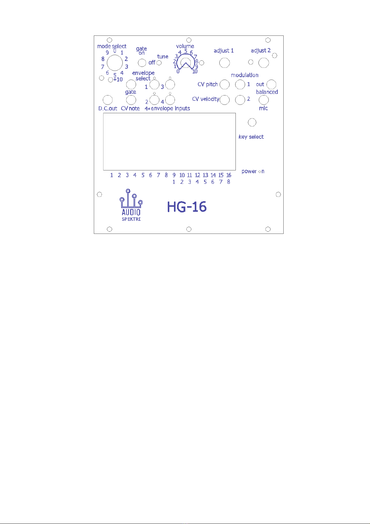
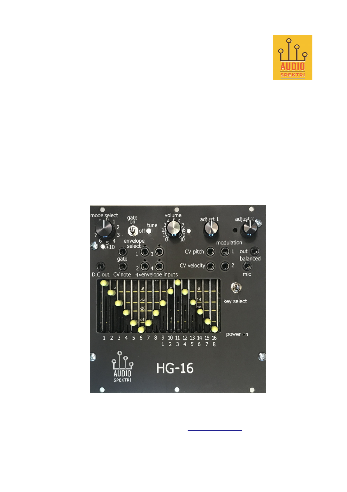
Figure 1: The HG-16 black front panel texts and outlines.
Front panel texts
The front panel texts are shown in the picture. To make it easier to find the controls in these instructions all the
words that can be found on the front panel of the synthesizer are emphasized in bold throughout the whole text.
A short list of the front panel texts and associated controls follows. Because several controls have different
functions in different operating modes you need to go to the actual mode to learn their specific detailed functions.
mode select: a 10 position rotary selector for selecting one of the 14 operating modes. The light emitting diode
under the +10 opening shows modes over 9.
gate on/off/envelope select: 3 position toggle switch routes the gate signal to the synthesizer also used in the
virtual switchboard programming. Mostly used in the off position see the mode instructions and virtual switchboard
instructions for details.
tune: fine tuning; typically not needed for user adjustment.
volume: main volume adjustment.
adjust 1 and adjust 2: mode specific adjustments multi-turn digital encoders.
D.C. out: constant voltage output useful in many modes as a constant “envelope” output.
4 x envelope inputs: inputs for external envelope control can be routed to any of the 30 sliders for dynamic
parameter control using the virtual switchboard positive voltage ranges.
CV pitch: input for the pitch bend control voltage signal; maximum +2.5V minimum -2.5V.
CV velocit : input for the key pressure velocity control voltage signal.
modulation 1 and 2: mode specific modulation inputs positive voltage range typically connected to external
envelopes.
gate: the note trigger input signal.
CV note: input for the note determining analog voltage 1V/octave scaling.
out balanced: main output mono balanced output. The output D/A has 24bit accuracy and working with the
4

standard 44.1kHz sample frequency except Mode 2 has a nonstandard frequency.
mic: microphone input used only in the vocoder modes.
1 – 16 optical potentiometer sliders typically for harmonic amplitude adjustment but also for mode specific
functions.
For some modes the arrangement uses two separate 8 slider sets therefore there are also duplicate numbers for the
sliders starting again from the 9th slider onward.
ke select: spring loaded switch used both for selecting the key to be played and +1 octave transpose (power-on
default is C major/A minor and base note C1). Simultaneous keyboard key activation and switch pulling is needed
for its activation. For +1 octave press any key in the current highest octave; for resetting back press any key in the
lowest octave or do power cycling. The transpose does not work in the vocoder modes.
power on: the led in the text is illuminated when power is connected to the board.
External connections and additional required modules not included
Most of the input jacks are compatible with mono 3.5mm patch cable jacks typically used in modular synthesizers.
The only exception is the microphone input mic that accepts a differential 3.5mm TRS (i.e. “stereo”) jack and used
only in the vocoder operating modes.
The main output has a balanced 3.5mm TRS jack. Only connect to an amplifier that also has a balanced
(=differential) input otherwise the noise level is unacceptable. Non-balanced stereo or mono inputs are not
compatible not suitable for headphone connection either.
The external required Eurorack modules that are not included with HG-16 package are:
–A MIDI interface module with bus-connected 1V/octave note control output and gate on/off signal. There are
dedicated input plugs in the front panel for them the gate and CV note.
The MIDI modules typically also have pitch bend and key velocity control outputs. These can be connected to
the corresponding HG-16 front panel jacks labeled CV pitch and CV velocit correspondingly.
–HG-16 requires at least one external envelope generator module preferably with several independent ADSR
outputs; maximum of 4 different can be connected. For less complex setups several envelope inputs and/or
modulation inputs can be connected together to a single generator output so suitable “multiples” rack modules
are recommended. However the delivery also includes two one-to-five 3.5mm modules that can alternatively
be used if your rack does not have excess multiples.
5

Connections and controls in detail
The group of four envelope input jacks need to be connected to envelope generator outputs. They tolerate positive
voltage from 0 to a maximum of +8 V. In most operating modes the full scale is reached with a 6 V input and
higher voltages will saturate. Their input impedance is 10 000 Ohms therefore a typical envelope generator can
easily drive several inputs simultaneously.
Mainly for testing purposes HG-16 has one constant voltage output labeled D.C. out that can be connected to the
envelope or modulation inputs. It allows playing the unit even without any external envelope generators. However
this means that you have a constant envelope for all the sounds or minimum attack/release duration if the gate signal
is switched on.
In most operating modes the minimum requirement is to connect one envelope generator output to input no. 1. but
the full functionality of HG-16 calls for several independent generators. Virtual switchboard circuitry is provided. It
routes the envelopes to control different features in the synthesizer: see the later section “Virtual switchboard” for
its instructions.
In the front panel there are also two additional inputs modulation1/2 with the same input characteristics as the
envelope inputs. They are used for various external modulation inputs and typically also require external envelope
outputs to be connected see their specific use in detail in each of the operating mode instructions.
When connecting patch cables between the inputs and outputs be careful to always plug the wire first to the inputs
and only after that to the outputs. This is to prevent accidentally shorting the hot plug end to the grounded metal
surfaces. It is especially important when using the D.C. out -terminal which has a low output impedance of 130
ohms.
The remaining connectors and controls in the front panel are the following:
–volume a typical output volume potentiometer.
–adjust 1 and adjust 2 are multiturn rotary knobs that have control functions specific to each operating mode.
–Three position toggle switch gate on/off/envelope select. The HG-16 black assumes that the modular
synthesizer gate signal is connected through front panel plug (contrary to the original HG-16 that had it bus
connected). In typical Eurorack systems the gate signal controls note activation and e.g. external envelope
triggering. However because the HG-16 relies on external envelopes and an external note determining VC
input it can be played both gate connected and disconnected from the bus. The unconnected state (toggle
switch center or “off” position) is mostly preferred because then you can also utilize the envelope generator
release functionality (i.e. when the gate signal would otherwise terminate the note). The operating modes 7 9
and 12 however require the gate to be connected so the toggle switch has to be in the “on” position in these
modes. The third position of the toggle switch “envelope select” is described in the section on the virtual
switchboard.
–16 optical slider potentiometers. As expected they are used for setting the amplitude of the 16 harmonics in the
basic mode however in the various operating modes they may have other uses see the mode documentations.
–Finally the mode select rotary selector is used for selecting one of the 14 possible operating modes of the
synthesizer. Note that modes over 9 have the led “+10” illuminated.
NOTE: rotate the selector rapidly from 9 to 0 or from 0 to 9 otherwise intermediate spurious switch states
prevent moving to or from the states over or under 10. However stay at least 1 second at 9 or 0 before the +10
border crossing because the selector has a rather slow debounce filter.
In addition to the front panel controls there are also three ground lift switches at the backside: They can be found at
a larger opening in the steel grille at the top of the enclosure. See their use in the section “Grounding and
shielding”.
6

List of Operating modes
The HG-16 has 14 different operating modes selectable by rotating the mode select knob. The mode selector only
has 10 positions therefore modes over 9 are indicated by the light emitting diode to the left of the selector. When
rotating the selector CW from 9 to 0 the diode is lit and you need to add 10 to the mode selector number.
Correspondingly when rotating the knob counter-clockwise (CCW) back from 0 to 9 the mode number goes back
under 10. The available control knobs sliders and patch cable inputs may have very different functions in each
mode so studying each mode instruction separately is needed. Note that there is some delay in the “+10” led so
avoid the rapid turning of several positions when going over 9 and under 10 otherwise the +/- 10 mode switching
may not react.
The modes are listed and shortly described here; see the later sections for a detailed description of each mode.
Mode 0: 16 harmonic frequencies with individual envelope control for each; common modulatable PM synthesis
and phase noise for each harmonic.
Mode 1: 8 harmonics with individual envelope control for each and individual modulation depth control (noise
and/or PM) for each using the remaining 8 sliders.
Mode 2: Harmonic filtered noise bands from a voltage controlled comb filter with individual envelope control for
each.
Mode 3: Base note with selectable interval notes maximum 7 each 8 harmonics.
Mode 4: Pseudo-VCF with noise control.
Mode 5: True chorus with 10 chorus members each 8 harmonics.
Mode 6: Single channel vocoder.
Mode 7: Frozen spectrum/transient capture single channel vocoder.
Mode 8: Two channel vocoder.
Mode 9: Frozen spectrum/transient capture two channel vocoder.
Mode 10: Same as mode 0 but only noise with two parameter controls.
Mode 11: Same as mode 1 but only noise with two parameter controls.
Mode 12: 15 harmonics with envelope control from a built-in sequencer.
Mode 13: Pseudo-VCF with PM control.
Mode 14: Frequency modulated harmonic generator.
In addition position 15 of the mode selector is used for selecting the software assisted tuning and calibration
facility and position 16 for factory linearity calibration.
7

Virtual switchboard
A key characteristic of the HG-16 is the employment of a virtual switchboard that allows any of the eight envelope
inputs to be routed to any of the 16 slide potentiometers which then will scale the external envelope signals
connected by typical patch cables from external envelope generators. A typical use would be to first determine a
steady state spectrum using the sliders (one slider for each harmonic) then the dynamic behavior by the external
envelope that was linked to each harmonic using the virtual switchboard. Depending on the operating mode the
sliders may have other control purposes but in most cases the same modulating linkage can still be used for the
alternative controls. The use of the virtual switchboard is described in the following.
At power-up all 16 sliders will be connected to envelope input no. 1 through the virtual switchboard. If the user
has previously defined some other configuration it can be reloaded from the nonvolatile memory by momentarily
flipping the toggle switch to the position "envelope select" and then returning it back to one of the other positions.
Note that the toggle switch has three positions: gate on (lever up) gate off (lever middle position) and envelope
select (lever down).
A routing configuration can be programmed and stored for each of the 16 sliders by turning the toggle switch to the
position "envelope select" and then moving the selected one of the 16 sliders. Each move either towards the
maximum or towards the minimum over a threshold location will advance the selected envelope channel by one.
Because the number wraps over from 4 back to 1 any of the four channels can be selected for the harmonic (or
other function) corresponding to the slider. The currently selected envelope channel is lit so the user can follow the
selection easily. When you flip the toggle switch back up the selected channel selection configuration is activated
and also stored in the nonvolatile memory where it stays over power down.
When in the programming position of the toggle switch any number of slider connections can be reprogrammed
without the need to toggle the switch back and forth between single slider programming events. Note that only the
last moved slider is activated therefore if you accidentally move more than one slider at the same time you need to
check back that all channels are in the desired order. If you leave the moved slider at the very minimum or
maximum after selecting channels such accidents are not likely to occur.
Note that in order to easily check the actual stored envelope channel configuration the first move of any slider in
the toggle switch down position does not advance the envelope channel selection but just shows the current stored
channel. So when the toggle switch is pushed down no channel indication leds are first lit. If you then move any
slider over its threshold up or down the previously stored channel is first illuminated for that slider and if the
toggle switch is returned back up without any additional slider movement no change of the channel configuration
has been done. Only if you continue moving the slider up or down after the first move the channel selection for the
slider will be changed and shown with the next illuminated led.
The stored configuration is specific to each of the synthesizer operating modes selected with the rotary switch.
However when you change the mode the current configuration stays. Only if you flip the toggle switch again the
previously loaded configuration is active for the new mode. This property can also be utilized for the purpose of
storing several alternative configurations for a preferred mode. Because there are 10+10 possible different positions
to be selected with the rotary mode select switch (and only 14 active operating modes) there are also 20 memory
locations for the different virtual switchboard configurations. Therefore it is possible to “steal” an alternative
switchboard configuration for any mode by turning the rotary selector from the current mode to some other mode
then flipping the toggle switch down and up again and returning back to the original mode by turning the rotary
selector.
Also note that when the 16 sliders are used for some other purpose than harmonic amplitude determination in some
other operation mode this switchboard channel programming may also apply to such situation. Please refer to the
detailed documentation of the selected mode.
8

Slider calibration
The slider maxima and minima are factory calibrated to follow approximately the decibel scale under the sliders.
If for some reason some of the sliders seem to be very different from the others there is a way to recalibrate them.
Keep the HG-16 running and the toggle switch in the “off” position. For the minimum value calibration push all
sliders to the minimum position. Then locate a hole to the right of the adjust 2 -knob. Under that hole there is a
small push switch that can be activated by pushing with a narrow stick. There should be a clear but low mechanical
click when pushing. Keep it pushed for a few seconds and release. Turn power off and on again. Then move all
sliders to their maximum positions and repeat the same action. Now the sliders should better follow the decibel
scale. The scale is very coarse so more accurate values can be found e.g. if you have a digital sound card with an
FFT spectrum display.
Note: Each recalibration requires prior power reset i.e. you cannot immediately redo calibration without turning
power down and up again nor do successive zero and maximum calibrations without power cycling in between! Of
course you first need to check the reason for the need to recalibrate. Because the optical potentiometer sliders do
not have dust covers prevent any debris from entering between them or inside the wedge-like opening in the sliders.
If there is dirt in the openings use gentle vacuuming to clean them.
uning
HG-16 uses a precision 12 bit A/D converter to convert the VC note signal from the bus to the note value. Therefore
it stays well in tune and normally tuning is not needed. However if the input VC note value is inaccurate HG-16
has means for compensating for the inaccuracies. The two common errors are:
1. An offset error: each C note should correspond to an exact integer VC voltage value. HG-16 scale starts at
C1 = 32.70Hz which corresponds to an input voltage value of 0V. A constant difference from the integer
values along the scale will make an offset error.
2. A scale error: the input should follow accurately the 1V/octave scale. If the scaling is incorrect there is an
increasing difference from the correct note when going the scale up.
HG-16 has a front panel opening below the text tune. Under it there is a trimmer for fine adjustment for
compensating possible input scale error. This is typically sufficient for normal situations. If not there is a software
facility for adjusting both the offset and scaling errors. Errors can also occur in the pitch bend signal (CV pitch
input) so they can also be compensated in software. This is described in the following.
Software tuning
For software tuning turn the mode select -knob to position 15. The output signal amplitude is now controlled only
by the volume knob. Only sliders 1 and 16 are functional in this mode. When slider 16 is fully down you can
compensate for VC note errors. When it is fully up you can compensate for errors in pitch bend and/or adjust the
pitch bend range. Start by moving both slider 1 and slider 16 fully down and connecting the output to a precision
tuner. Play C1# in the keyboard (not C1 because C1# allows you to observe both positive and negative offset
errors). The offset error can now be zeroed by turning adjust 1. Only the internal A/D offset is compensated so the
adjustment range is small. For large offset error compensation see the pitch bend offset compensation section later.
Next play a high note e.g. C5 and use adjust 2 for possible scale error compensation. If no pitch bend corrections
are needed you can now raise slider 1 fully up. This move will burn the new calibration values to the nonvolatile
memory.
Pitch bend tuning
If pitch bend adjustments are needed keep slider 1 down and move slider 16 fully up. Connect your pitch bend
signal source to CV pitch. Check that the pitch bend signal is inactive. Use adjust 1 to compensate for possible
pitch bend offset. Activate the pitch bend signal and use adjust 2 for adjustment of the desired range. Again when
slider 1 is moved up the values are stored in the nonvolatile memory.
Warning: The sum of VC note and pitch bend offsets make the total note offsets. Therefore pitch bend offset can
also be used for compensating such large offset errors in the VC note signal that are out of its own adjustment
range. However then you have to remember that when you disconnect the CV pitch source the tuning is different.
Also if you have adjusted the pitch bend offset you have to redo the VC note calibration process described above.
Because during this tuning process it would be impossible otherwise to find out which offset is wrong there are
additional means for hearing the difference: With zero or disconnected CV pitch bend the output signal has both
9

the fundamental and second harmonic at equal amplitudes when the pitch bend signal is close to zero. Otherwise
only the fundamental frequency can be heard. Therefore you can find the ideal situation when there is zero voltage
at the pitch bend input - and it thus has no effect on the note - by adjusting adjust 1 when slider 16 is up until you
hear both. If you need to adjust the pitch bend offset so large that only the fundamental is heard then you have to
remember that disconnecting pitch bend will change the tuning.
Grounding, shielding and RF interference
Inputs
The Eurorack community is diverse therefore the common grounding and signal shielding practices may not be
obeyed in all environments. There should be only one common ground between the different modules in a rack the
bus ground strip. Multiple grounding points may generate ground loops that add noise to sensitive inputs. However
typically patch cables also carry a signal ground in their sleeve contact. This is usually not a problem for such low
output impedance large amplitude signals that are applied to e.g. the envelope inputs within the same rack.
However in a case when signals from a remote rack are connected to the HG-16 inputs large ground loops may be
created. The unwanted additional ground usually comes from a common power jack safety ground connection so
the obvious remedy is to use systems with fully isolated power supplies. The secondary remedy is to use the HG-16
ground lift switches. Note that there should still be at least one common signal ground and hopefully close to the
most sensitive input. Therefore it may not be a good idea to lift all the switches because then the possibly remaining
common ground may be close to some noisy power supply lines. The HG-16 ground lift switches correspond to
three regions in the circuitry. If you keep the circuit board positioned so that the ground lift switches are up and
look from the backside of the system the leftmost switch (no. 3) is connected to the Modulation 1 input ground
the middle one to Modulation 2, CV pitch and CV velocit grounds and the third to all the envelope input
grounds. The switch levers are very short so use a small sharp tool for lifting the levers.
Outputs
The HG-16 outputs have their signal grounds permanently connected. Because the signal output has a balanced
differential output it does not necessarily need a separate signal ground so if there are noise problems use the
receiving amplifier ground lift switches. Or if there are none you can even disconnect the signal cable shield from
the ground (but only at the output side).
RF/EM Interference
The HG-16 has high speed digital circuitry therefore special concern has been paid to prevent high frequency
emission to sensitive analog circuitry inside the same rack or outside it. All the inputs and outputs have RF filters
tuned to block high frequency signals. The module has grounded metal shielding on both sides: the front panel has a
grounded copper layer and the backside has an iron grille. The exposed front opening at the sliders has the slider
support bars also grounded. When connecting the module in a (metal) rack the attachment screws also connect the
chassis to the rack metal parts that are typically grounded but separately from the signal ground.
PM vs FM
The HG-16 has two different periodic modulation methods phase modulation (PM) used in several modes and
frequency modulation (FM) used only in Mode 14. The difference of these methods in terms of resulting signal
characteristics is described in the following.
As the name suggests PM varies the instantaneous phase of the sinusoidal signal by the modulating waveform. The
result is a controlled distortion that can be heard as increasing harmonics with increasing modulating signal
amplitude. Because several of the operating modes have the possibility to add independent modulation to distinct
harmonics each harmonic will correspondingly be distorted therefore creating very spectrally rich signals within
separately controlled spectral areas. Because the modulation is limited inside the base frequency period all the
distortion components will remain harmonic (except for some modes that allow signal folding/aliasing with extreme
modulation).
FM adds frequency shifting modulation over an arbitrary period that is not limited within the modulated signal
period like in PM. Therefore the resulting spectrum is not limited to harmonics of the modulated signal. Most
percussion instruments have nonharmonic spectra therefore FM is useful for generating percussive sounding
signals e.g. when the modulation comes from an envelope generator signal with steep amplitude variations. In fact
many instruments that are periodic in their steady state have complex nonperiodic spectra within their attack and/or
decay periods. Such periods can easily be generated in the HG-16 because the modulation parameters can be
controlled with external envelope generators even independently for each generated harmonic.
10

Operating modes in detail
Mode 0: 16 harmonics, lobal noise and phase modulation
The first operating mode generates 16 harmonic frequencies with individual envelope control for each using the
corresponding 16 sliders. In addition to the nominal amplitude set by the sliders each harmonic can be dynamically
modulated by an external envelope generator output when connected to one of the 4 envelope inputs. The process of
determining which one of the 4 possible envelopes is being used for each particular harmonic has been described
earlier in the section “Virtual switchboard”. Additionally there is the possibility to add phase noise for each of the
harmonics. The noise can be dynamically controlled by connecting an envelope signal source to the modulation 1
-input. The modulation strength of the envelope is adjusted using the multi-turn knob adjust 1. Turning the knob
CW will increase modulation strength and decrease when turned CCW. Reaching the maximum or minimum
values will blink the overload led next to the volume control then further turning has no effect.
In the same way there is the possibility to add phase modulation (PM) synthesis modulation using input
modulation 2 and adjust its strength using adjust 2. For this adjustment only the minimum rotation is indicated by
the overload led. This is because excessive modulation creates a very noisy and spectrally rich signal that could be
used for special effects if not for musical purposes.
The other inputs CV pitch and CV velocit are used in the typical way i.e. the former for pitch bending and latter
for key velocity based amplitude control. These signals are available from typical MIDI input modules (not
included).
Note that adding simultaneously both noise and PM is also possible. However in that case also some constant band
low frequency noise will be added in addition to the band limited voice around the selected harmonic. Some of that
noise is filtered away but not all otherwise also the lowest harmonics would be filtered out.
Tip: because the settings are quite complex you can ease testing by connecting the D.C. out to modulation 1 and
modulation 2 and do the adjustments with a constant note VC in. If you have access to a spectrum analysis SW
(included in most DAWs) then you can also observe how the spectrum looks while listening. Remember always
first to connect the patch cable to the inputs and only after that to D.C. out to avoid shorting the output.
As a summary here is a list of the patch cable connections required:
1. Connect envelope generator outputs to all those of the envelope inputs that you have activated for the
desired harmonic sliders. (see the section "Virtual switchboard"). Remember that on power up all are
connected to input 1 and only if you toggle the switch to "envelope select" position and back again
the previously stored connections are activated.
2. If you want to use the noise and/or PM modulation features connect also envelope generator outputs
to modulation 1 and/or modulation 2.
3. Connect the note determining control voltage to the CV note input and the gate trigger signal to the
gate input and optionally connect the CV pitch and CV velocit inputs to the corresponding MIDI
input module outputs.
11

Mode 1: 8 harmonics, individual noise and phase modulation
Mode 1 is similar to Mode 0 with the following exceptions:
–only 8 harmonics are generated
–the noise and/or PM modulation strength for each of the 8 harmonics can individually be adjusted using the
corresponding sliders 9 - 16 i.e. they can be used for weighing the input fed to modulation1 / modulation 2.
The individual adjustment allows creation of complex spectra that have sections of noisy or clean areas when the
noise adjustments are used. The individual phase modulation on the other hand adds variable spectra that are
harmonics of the selected overtones instead of the fundamental only.
12

Mode 2: Comb filtered pseudoperiodic si nal
Mode 2 uses a white noise source as an input to a comb filter thereby creating a pseudoperiodic harmonic signal.
The speed of the filter is adjusted using the input note control voltage therefore the apparent pitch of the
pseudoperiodic signal follows the same calibrated note pitch as the other modes.
The comb filtered signal is fed to a 15 channel bandpass filter and its output levels can be adjusted with the first 15
sliders and modulated by any of the 4 envelope input sources selectable as described before. Furthermore the
comb filter feedback can be adjusted making the output signal more or less noisy: i.e. when there is no feedback the
white noise is fed raw to the 15 BP filters. The filters are also tuned to harmonic center frequencies so the same
apparent pitch still remains although very noisy. When the comb filter feedback approaches unity the noisiness
decreases and the signal goes closer to a periodic harmonic signal; if only one slider is up and others in the fully
attenuated position the signal is closest to a sinusoid but obviously still quite noisy.
The comb filter feedback coefficient can also be adjusted and modulated allowing very dynamic sounds to be
made varying between noisy and more sinusoidal signal with the envelope amplitude. The modulating envelope has
to be connected to the modulation 1 input. The sensitivity for the modulation can be adjusted using the adjust 2
knob and the modulation feedback offset value corresponding to zero modulation amplitude using the adjust 1
knob. The modulation direction can be either from noisy to less noisy or the opposite direction. This is controlled
by Slider 16 that works in on/off mode: when Slider 16 is fully down or off increasing modulation amplitude
increases the noise level and when Slider 16 is up increasing modulation amplitude decreases the noise level.
Note that the release rate from high noise to low noise is slow because the comb filter stabilization takes some time.
When moving to the opposite direction the rate is fast.
modulation 2 has no effect in this mode. Furthermore the Eurorack gate signal is not used in this mode even if the
toggle switch is in the “on” -position. Therefore the output level is all the time controlled by the external envelope
inputs linked to the corresponding sliders.
Notice that because the signal is fully created from noise the noise floor is also much higher than in the other
modes. This is not a flaw but inherent for this synthesis method because this mode uses subtractive synthesis and
the applied bandpass filters do not have infinite stopband attenuation. You can also note that the noise floor is
clearly lower if you move slider 1 off and instead use the other sliders for the corresponding amplitude control of
the pseudoharmonics.
This mode has been found especially useful for noisy flute -type of voices. This is demonstrated by several sound
samples in the download section including exaggerated samples. You can also hear a clear difference from the
signal of e.g. Mode 0 even if you try to adjust the harmonics noise bands equal. All noise is not created equal!
As a summary here is a list of the patch cable connections required:
1. Connect envelope generator outputs to all those of the envelope inputs that you have activated for the
desired harmonic sliders. Only sliders 1 to 15 are usable in this mode. Remember that on power up
all are connected to envelope input 1 and only if you toggle the switch to "envelope select" position
and back again the previously stored connections are activated.
2. If you want to have the noise modulation function connect also envelope generator output to
modulation 1. If you want to keep the noise at constant level you can alternatively connect
modulation 1 to D.C. out and adjust the noise to desired level using adjust 1 and adjust 2. Use
slider 16 to determine the modulation direction.
3. Connect the note determining control voltage to the CV note input and optionally connect the CV
pitch and CV velocit inputs to the corresponding MIDI input module outputs.
13

Mode 3: Base note with selectable intervals
This mode can generate the whole set of musical intervals within one octave i.e. maximum of 7 notes. Each note
then can have a maximum of 8 harmonics. The first 8 sliders are used in the same way as in the basic form for
controlling the corresponding harmonic amplitudes. These are identical for all the notes but obviously the spectral
envelopes will differ due to the interval distances. The sliders 9 – 15 are used for setting the interval amplitudes
above the base note. The numbers below the upper ones clarify the intervals i.e. 1 (below 9) for the base note 2
(below 10) the second 3 for third etc up to the seventh. The total maximum of spectral peaks then is 7 x 8 = 56
although seldom all the intervals are used simultaneously if not for special effects.
The key selection is made by pulling the spring loaded “key select” switch up simultaneously when pushing down
the desired major key in the keyboard. The dual keys naturally follow this setting i.e A minor also is selected when
the C key is pressed Bb minor also results when the C# key is pressed etc. The default key at power up is C
major/A minor.
Note that because both the harmonics and the chord elements can be modulated by one of the 4 selectable envelopes
as described before you can make e.g. quite complex glissando-type effects when using envelope controls with
different durations for the different chord notes or even make a transition from one chord to another during the
activation of a single base note. In the case of rapidly varying envelopes such activation would be quite tricky to
achieve "manually" with a normal polyphonic keyboard.
The slider 16 is not used in this mode neither knobs adjust 1 nor adjust 2.
As a summary here is a list of controls and the patch cable connections required:
1. Connect envelope generator outputs to all those of the envelope inputs that you have selected for the
desired sliders using the virtual switchboard. Note that both the harmonics (sliders 1 to 8) and the 7
interval amplitude responses (sliders 9 to 15) can be modulated. Remember that on power up all are
connected to input 1 and only if you toggle the switch to "envelope select" position and back again
previously stored connections are activated or you can program new connections.
2. Pull up the “key select” switch to select the key to be played.
3. Connect the note determining control voltage to the CV note input and the gate trigger signal to the
gate input and optionally connect the CV pitch and CV velocit inputs to the corresponding MIDI
input module outputs.
14

Mode 4: Pseudo-VCF with noise control
Mode 13: Pseudo-VCF with PM control
Although this mode uses additive synthesis it is still possible to do signal processing that closely resembles voltage
controlled filter (VCF) operation. In vintage analog synthesizers VCF was one of the main attractions. In this mode
the harmonic generator makes 8 harmonics that are fed to a spectrum shaper. The harmonic levels from the
generator are controlled using sliders 1-8 while sliders 9 - 16 are used to determine the pseudofilter spectral
response in the same way as a typical graphic equalizer would do. The 12 center frequencies of the sliders 9- 16 are
listed in the following at the reset condition. (because the sliders starting from 16 also have additional numbers
starting from 1 they are also used here in parentheses for convenience):
9 (1): 121Hz
10 (2): 269Hz
11 (3): 550Hz
12(4): 915Hz
13 (5): 1450Hz
14 (6): 2150Hz
15 (7): 2930Hz
16 (8): 3750Hz
The last 4 pseudofilter passbands are controlled by the same sliders as the first 4 ones but onl if there is some
signal at envelope input 3. If envelope 3 has zero voltage input then only the first 8 pseudofilter bands are active.
9 (1): 4750Hz
10 (2): 6100Hz
11 (3): 7750Hz
12 (4): 9500Hz
The -6dB points of the "filters" are adjusted to coincide with the neighboring filter -6dB corners. Because additive
synthesis allows perfect attenuation the pseudofilters have zero responses outside their designed width. These zero
response corners are set to match the center frequencies (=maxima) of the adjacent pseudofilters.
The VCF function can be activated by feeding a frequency control envelope to modulation 2. At reset or when
coming from some other mode the modulation sensitivity for that input is zero. Only when you rotate the adjust 2
knob the sensitivity for the external modulation increases. When rotating CW an increasing modulating voltage at
modulation 2 will shift the pseudofilter center frequencies higher. Correspondingly rotation of adjust 2 CCW from
the reset state will shift the center frequencies lower with increasing modulation voltage. As usual you can
alternatively connect the D.C. out voltage to modulation 2 and use adjust 2 to shift the pseudofilter bands to fixed
lower or higher frequencies. The magnitude of the frequency shift in response to the modulation is equal to all the
pseudofilter bands.
Note that when compared to real filters the time domain responses of the pseudofilters do not have relation to the
filter steepness. Therefore a very rapid frequency modulation will make slight clicking or arpeggio-type voices that
may also be useful for some special effects. Of course if the adjacent slider differences are small the spectral
changes will appear smoother.
In addition to the frequency shifting -type of voltage control this mode also allows amplitude modulation of each of
the pseudofilter responses. Modulation can be activated for the bands corresponding to sliders 9-16 from any of the
4 envelope inputs using the virtual switchboard in the same way as for the harmonic frequencies. Again note that
the reset condition defaults to envelope input 1 for all the sliders and the stored configuration or new configuration
can be loaded by using the toggle switch as described earlier.
The difference between modes 4 and 13 is their use of additional modulation. Mode 4 has similar noise control
available as found in Mode 0. A noise modulating envelope can be connected to modulation 1 and the sensitivity
adjusted using adjust 1. Correspondingly in Mode 13 they are used for phase modulation and sensitivity.
15

An interesting feature in Mode 13 is that because the filter is pseudo-VCF and not a real the harmonics created by
the PM are not filtered out based on their own frequency but instead based on the frequency of the fundamental that
was modulated. As an example if you have a harmonic at a frequency of 550Hz then its amplitude is determined
by Slider 11 (provided no modulation is controlling VCF at modulation 2 or adjust 2 is at its reset position). When
PM strength is increased by modulation 1 & adjust 1 it creates harmonics at multiples of the 550Hz frequency but
still all these harmonics are also controlled by Slider 11. This way you can get very dramatic spectral effects just by
one modulating input at modulation 2.
As a summary here is a list of the patch cable connections and adjustments:
1. Connect envelope generator outputs to all those of the envelope inputs that you have activated for the
desired harmonic sliders 1 – 8 and for the filter amplitude sliders 9 – 16. Remember that on power up
all are connected to input 1.
2. Connect envelope generator output to modulation 2 to do the center frequency modulation of the
pseudofilters; use adjust 2 to control its sensitivity.
3. If you want to use the noise features (Mode 4) or PM (Mode 13) connect also envelope generator
output to modulation 1and use adjust 1to set the modulation level.
4. Connect the note determining control voltage to the CV note input and the gate trigger signal to the
gate input and optionally connect the CV pitch and CV velocit inputs to the corresponding MIDI
input module outputs.
–Use sliders 1 -8 to set the harmonic spectra.
–Use sliders 9– 16 to set the pseudofilter spectral response.
–If you want to use the 4 highest bands connect a signal source also to envelope input 3.
16

Mode 5: True chorus with 10 chorus members, each havin a
maximum of 8 harmonics. Also the possibility to enerate non-
harmonic overtones.
Mode 5 generates 10 different fundamental frequencies each with a maximum 8 harmonics. The fundamental
frequencies are generated close to each other therefore making a true chorus of 10 members ("true" used here to
emphasize the difference from typical chorus effects that loop the same voice to create a similar effect). The
difference of the frequency of the individual voices can be adjusted using adjust 1 and also modulated using an
envelope connected to modulation 1. The maximum deviation of the chorus voices from the nominal note
frequency is a little more than +- one full note. All the 10 voices will be inside this range with approximately equal
distances. At reset all voices are at the nominal note and you need to turn adjust 1 CW to increase the deviation
with some envelope or D.C. out connected to modulation 1.
The spectra of the chorus voices can be adjusted and modulated in the same way as in Mode 0 i.e. using sliders 1 -
8 and their linked envelope inputs. All the voices have identical spectra (save the fact that all the harmonic
frequencies follow the same relative frequency shift as their fundamentals).
The last 8 sliders from 9 to 16 are used to control the relative amplitudes of the chorus members in the logical order
from the lowest to the highest. Note that these can also be modulated in the same way as harmonics i.e. by linking
the sliders 9 -16 to some of the envelope inputs 1 – 4 through the virtual switchboard. Figure 3 shows an example
with 10 chorus members each having just 3 harmonics.
This mode also has the possibility to adjust the harmonics outside of harmony by turning adjust 2 CW. The whole
group of 10 overtones will be shifted equally. The direction of shift is always towards higher frequencies from the
nominal harmonic frequency up to 1.8 times the nominal frequency. This adjustment can be used to generate voices
that resemble natural non-harmonic voices like bells or drums with proper envelope shaping of amplitudes. The
adjustment using adjust 2 advances stepwise generating audible clicks therefore not useful during live
performance.
A drawback from the true chorus operation is that such close frequencies inevitably will interfere i.e. make beating
effects with their periods varying inversely proportionally to the frequency difference. If the amplitudes are
identical there will be periodically almost complete cancellation and full double amplification of the beating
harmonic (note that they occur at different fundamental frequencies for different harmonics). For avoiding the full
cancellation it may be useful to use different amplitudes for the chorus members by adjusting sliders 9 - 16 and
when both the deviation and the individual amplitudes are modulated dynamically the beating will not be periodic
and not so disturbing. If acceptable also slight shifting of the overtones out of harmony can be used for adjustment.
As a summary here is a list of the patch cable connections and adjustments:
1. Connect envelope generator outputs to all those of the envelope inputs that you have activated for the
desired harmonic sliders 1 - 8. Remember that on power up all are connected to input 1.
2. Correspondingly Connect envelope generator outputs to to all those of the envelope inputs you have
activated for the desired harmonic sliders 9 - 16 to control the chorus member amplitudes. If you want
to keep the member amplitudes constant connect the selected envelope inputs D.C. Out.
3. Connect an envelope output to modulation 1 if you want to modulate the frequency deviation of the
chorus. Otherwise connect D.C. Out to modulation 1 to keep the deviation constant. With no signal at
modulation 1 there is no chorus.
4. Connect the note determining control voltage to the CV note input and the gate trigger signal to the
gate input and optionally connect the CV pitch and CV velocit inputs to the corresponding MIDI
input module outputs.
–Set the chorus member spectra by sliders 1-8 (all members have identical spectra) and relative chorus
member amplitudes using sliders 9 -16. Note that slider 9 controls three chorus members while the rest 10
– 16 each control a single member.
–Use adjust 1 to control the sensitivity to the signal at modulation 1.
–Use adjust 2 to shift the overtones out of harmony if desired.
17

Mode 10: 16 harmonics with two parameter noise control
This mode is similar to Mode 0 with the following exceptions:
–No phase modulation.
–modulation 2 is used for modulating the setting of adjust 2 (see its description below; modulation 1 still
controls the noise amplitude).
–adjust 1 and adjust 2 are both used for noise adjustment. Their operation is described in the following.
adjust 1 works in the same way as in Mode 0 i.e. when turned fully CCW (until the overload led blinks) the noise
is minimized and turning it CW noise gradually increases. adjust 2 works by varying the duration of the noise
injected to the periodic waveform. Because the noise acts as an additive phase component for sinusoidal harmonics
increasing the duration beyond the sinusoid period will cause frequency shift. Turning it CCW until the led blinks
minimizes the duration and then the noise is similar as in Mode 0. When adjust 2 is turned CW the noise injection
period slowly increases. This has the effect of randomly varying the frequency of all the harmonics. adjust 1
continues to adjust the amplitude of the noise (multiplied by the envelope connected to modulation 1) so there will
be varying effects when these two are adjusted.
When the noise injection period with adjust 2 is kept moderate and the amplitude of noise is varied with adjust 1
there will be clicking-type noise with varying strength (modulated by modulation 1 input). When adjust 2 is
turned more CW the effect will sound more like random frequency hopping of the harmonics rather than noise.
The hopping period is increased with increased CW turning of adjust 2 so the signal spends more time at the
random frequencies. Notice that the range of adjust 2 is several tens of full rotations so you can hear the frequency
hopping slowly slow down when you turn it CW. Again it is convenient to connect modulation 1 to the D.C. out
-terminal for testing or adjustment trials.
The envelope connected to modulation 2 has the effect of multiplying the setting of adjust 2. If it is 0V or left
open the noise injection period remains at zero therefore adjust 2 has no effect; the same applies to adjust 1/
modulation 1. Again for testing or if you just want to keep the noise parameters constant connect D.C. out to
modulation 1&2.
Tip: In other modes that have the phase noise adjustment the bandlimited noise slowly increases. In this mode the
audible effect is effectively multiplied by adjust 2. Therefore if you first do a large rotation of adjust 1 and only
then turn adjust 2 CW the result is very chaotic frequencies within the full audible spectrum. Therefore it is
recommended that you work by turning successively a little both adjust 1 and 2 and listen how the combined effect
varies the sound.
Mode 11: 8 harmonics with individual two parameter noise control
This mode is similar to Mode 10 with the exceptions:
–only 8 harmonics
–the noise modulation amplitude for the 8 harmonics is individually controlled by sliders 9 - 16. Thus selected
harmonics can be kept noise free by keeping their sliders at minimum while others have adjustable noise
strengths determined by their slider settings as described in Mode 10.
18

Mode 12: Harmonic enerator with built-in sequenced envelope
enerator
This mode can generate a signal with 15 harmonic frequencies. Instead of the external envelope generator inputs an
internal one is used and its output is fed to a virtual delay line so that a maximum of 4 delayed envelope waveforms
can be used for modulating the harmonics. No external envelopes can be used in this mode save the one that may
optionally be used for controlling the PM synthesis feature for all the harmonics through the modulation 2 input.
The internal envelope generator only has control on the attack period of the envelope which is the most important to
the instrument timbral characteristics. The release period is fixed to a relatively rapid decay rate.
The knobs adjust 1 and adjust 2 are used for the envelope shape determination. Adjust 1 controls weighing
between two alternative attack waveform shapes the other a monotonously rising waveform and the other a
sinusoidally varying overshooting waveform. Figure 12.1 shows the resulting envelope shapes with the two
extreme adjustment cases when turning adjust 1 and one middle adjusted case.
The toggle switch has to be in the gate on position to trigger the envelopes.
adjust 2 is used to vary the speed of the envelope attack edge together with Slider 16. When turning adjust 2 CW
the speed is increased i.e the attack period becomes shorter for both the monotonous and overshoot waveforms. It
also correspondingly compresses the periods between the 4 sequenced outputs. CCW rotation correspondingly
increases the durations of the envelopes. Slider 16 is used as an adjustment for the trigger delays between the
internal envelope generator outputs. Raising the slider will increase the delay between the 4 sequenced outputs. The
total duration of the delay also depends on adjust 2 that controls the speed to run through the delay.
All the sequenced waveforms will have identical shape only their delay from the gate trigger is different. For all the
15 harmonics corresponding to the sliders any of the 4 differently delayed identical waveforms can be selected.
The selection is done exactly in the same way as selecting one of the external envelope inputs in the basic mode
i.e. by turning the toggle switch down to the position "envelope select" and then moving the selected slider up and
down until one of the lit leds next to the 4 envelope inputs shows the desired delay. The delay length corresponds
to the order number of the input so if the led next to the input 1 is lit for the moved slider the corresponding
harmonic has zero delay; if it is lit next to input 2 it has 1/4th part of the total delay and if next to input 4 it has the
maximum delay. Returning the toggle switch back up will activate and store the corresponding delay setup in the
nonvolatile memory.
Similarly to the basic mode when you power the system up all delays default to 0 corresponding to input 1 and
only when you momentarily flip the toggle switch down and again up the stored delay setup is recalled.
Because no external envelopes are used you need to keep the toggle switch turned up in the gate on -position for
playing in order to get the note start trigger signal the gate signal for the envelope generator. Note that the gate
trigger signal has to be connected from an external source..
An optional input can be used for modulation 2. It controls the phase modulation of all the harmonics equally. With
zero voltage or no input there is no modulation and all the harmonics are pure sinusoids. There is no other control
of the modulation strength like in the basic mode so for this input you probably will like to use an external
envelope generator with good amplitude control because the maximum voltage level of about 6 volts will make an
extremely spectrally rich modulation result.
Tip: One example of acoustic instrument -type sounds is generated when you have adjust 1 fully CCW adjust 2
turned to make a pretty rapid transient and a fast attack-decay envelope connected to modulation 2. The resulting
sound is close to trumpet because the fast tremolo from the overshooting amplitude envelope resembles the player
lip action and the short PM modulation during the attack period makes an effect that is somewhat similar to the
trumpet spectrum variation.
As a summary here is a list of controls and the patch cable connections required for Mode 12:
19

1. The external envelope generator inputs 1 - 4 need not to be connected (if you have cables already
connected to them no harm you can keep them connected but they have no effect).
2. If you want to use the PM modulation feature connect also an envelope generator output to
modulation 2. Maybe it is best to first try without any connection. adjust 1 or adjust 2 do not have
control on the PM modulation sensitivity therefore the envelope amplitude directly makes the PM.
3. Use slider 16 and adjust 2 to control the speed and inter-envelope delays of the 4 envelopes and
adjust 1 to control the envelope shapes.
4. Connect the note determining control voltage to the CV note input and the gate trigger signal to the
gate input and optionally connect the CV pitch and CV velocit inputs to the corresponding MIDI
input module outputs.
5. Keep the toggle switch in the gate on -position to trigger the internal envelopes; alternatively use
modulation 1 as the trigger input but leave it open if gate is used for triggering.
6. Check the harmonic slider virtual link connections to the envelope inputs 1 - 4 because they
determine the internal envelope generator delays.
Figure 12.1: Mode 12 is the onl mode that uses an internal envelope generator/sequencer. The three envelope
plots show the effect of adjust 1 at the two extreme cases (left & right), and in the middle adjusted case for the
attack period of the note. The duration can be adjusted using adjust 2, and each of the 16 harmonics will have a
similar cop of the envelope, but with the selection of 4 different possible dela periods from the gate trigger.
20
This manual suits for next models
1
Table of contents
Other Audiospektri Synthesizer manuals


