manuals.online logo
Brands
  1. Home
  2. •
  3. Brands
  4. •
  5. Audiovox
  6. •
  7. Car Speakers
  8. •
  9. Audiovox CE-100 User manual

Audiovox CE-100 User manual

IMPORTANT- This system is designed for Univenal Installation of many different Manufacturen equipment. When
required, specific instructions or templates included in this package are provided when the Universal Mounting Method is
not applicable.
I. Selection of the Mounting Area
Note: Specific templatesareincluded for J.I. CaseModel 580K equipment. Useuniversal templatefor John Deere, Caterpillar,
Fiatallis and other manufacturers.
A. This product is designedfor overhead (roof) mounting in vehicles where a dashmounted radio is not practical. The usual
application includes construction vehicles, agricultural vehicles, and othersprovided they havean enclosedcab.
B. Since the product is to be mounted overhead, specialconsideration should be given to placement,accessibility for useand
safety.As for placementtheunit shouldbecenteredabovetheoperatorandslightly forward. Accessibility to theradio's controls
andfunctions is necessary,sothe unit shouldbelocatedwithin reach.Safetycannotbeignored. Usagemust benot distract the
operator any more than a conventional dashmounted unit would. Also sincethe unit is to be mounted overhead. you must
considerit asanormal obstruction that theoperatorcould comein contactwith. This isespeciallytrue in vehicles that normally
operateoff road.
C.With the three previous main considerations examined, you should now selectthe mounting area.The final consideration is
mechanical mounting capabiltiy. Examine the mounting illustration andverify the selectedareais suitable for drilling of the
two bolt holes,wiring accessetc.Usethe templateprovided to verify sufficient spaceexistsonthe mounting areato acceptthe
unit.
2. Pre-InstalIlation Checks
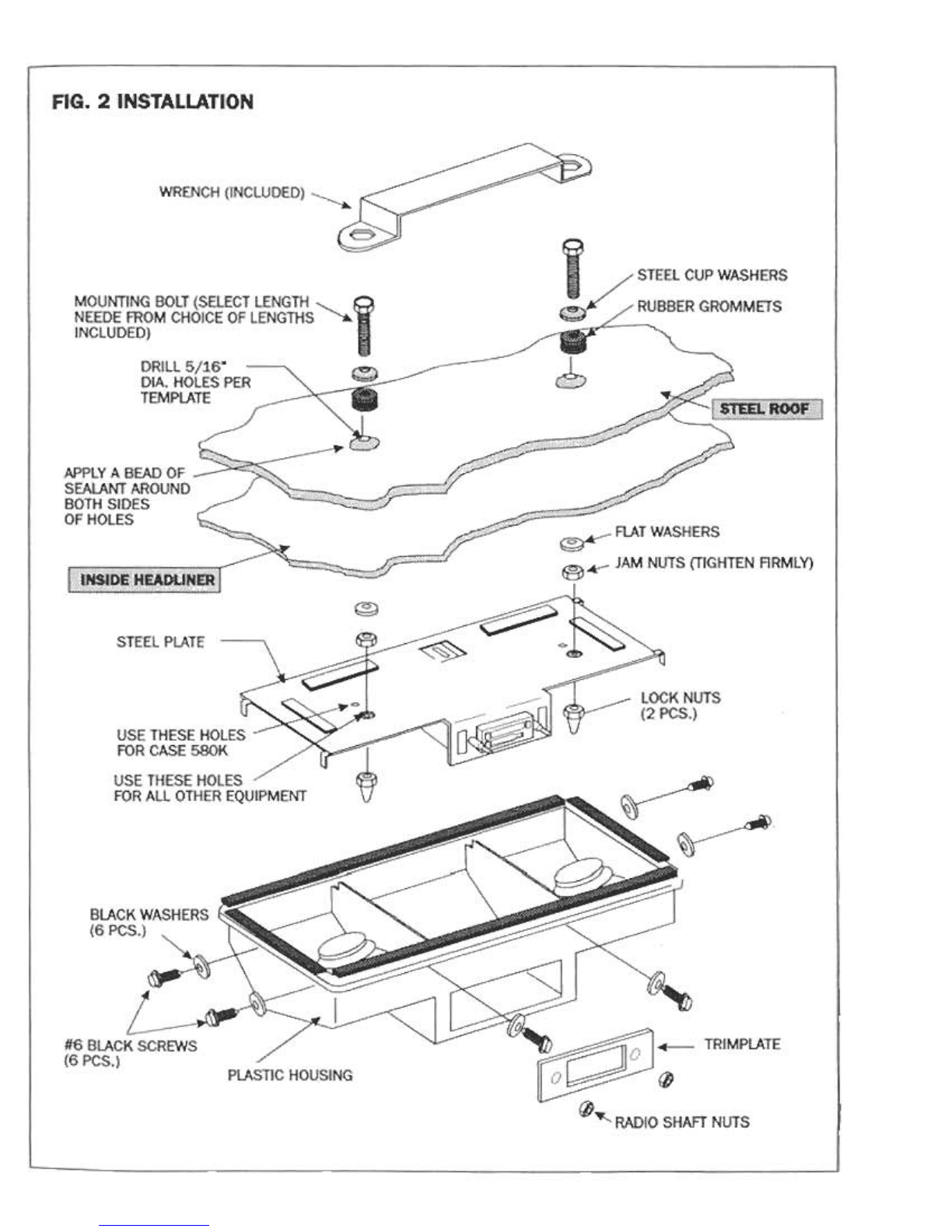
A. Determine the cabroof structure. It is like Fig. A, Fig. B, or Fig. C.
B. If it is like Fig. A, you must install the CE-3100 asshown in Fig. I
C.1f it is like Fig. B, you must install the CE-3100 asshown in Fig. 2
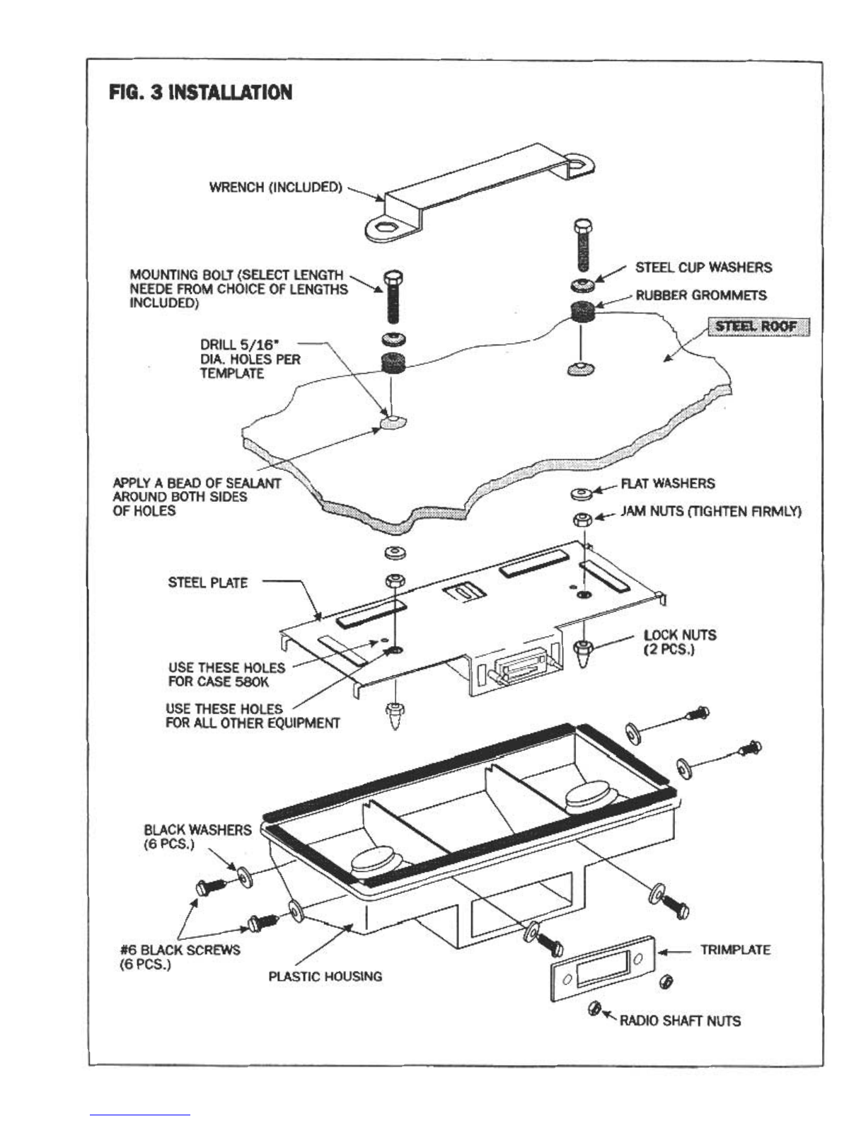
C.1f it is like Fig. C. you must install the CE-3100 asshown in Fig. 3
3. Antenna Installation (Roof Mounting)
A. The universal antennamaybemounted on the top of the roof or on the sideof the cab.Refer to the instructions included with
the antenna for side mounting.
Note:to insure a leak proof mount.
B. AI\vavs mount the antennawithin reach of the radio (the cableis 59" long).
C.It is easierto drill the antenna mounting hole and mount the antennabefore proceeding with the radio installation.
D.T\vo typesof mounting conditions mayexist:
I. If the roof hasno liner or if the liner is tight against theundersideof the roof (no air gap),youwill drill a 3/4" hole through
the roof and andthe roof liner (total thicknesscannotexceed3/8"). Also the hole mustbelocatedoutside the mounting plate
or it will interfere with the antenna mounting.
2.If the roof hasa roof liner and there is an air gap of at leasttwo (2") inchesbetweenthe liner and the underside of the rrof.
you will drill a 3/4" hole only through the roof (do not drill through the liner). You can also mount the antenna anywhere
including directly abovethe radio areasisncethe 2" gapwill prevent any interference.
E. Oncethe hole is isdrilled, install the antennabyfollowing the instructions included with theantenna.Usesealantto insure the
antenna mounting hole will not leak.
F. If the vehicle hasa roof liner, you will haveto drill a 3/8" hole in the liner to route the antennacable out of the roof. This
hole should be drilled ascloseto the "Wiring Access"hole shown on the radio mounting.
Note: If roof mounting of the antenna is not practical, the antennacan be mountedon the sidesofthc cab or other areas(se(
antenna instructions). This location should always allow the antennato be ashigh aspossible for maximum reception
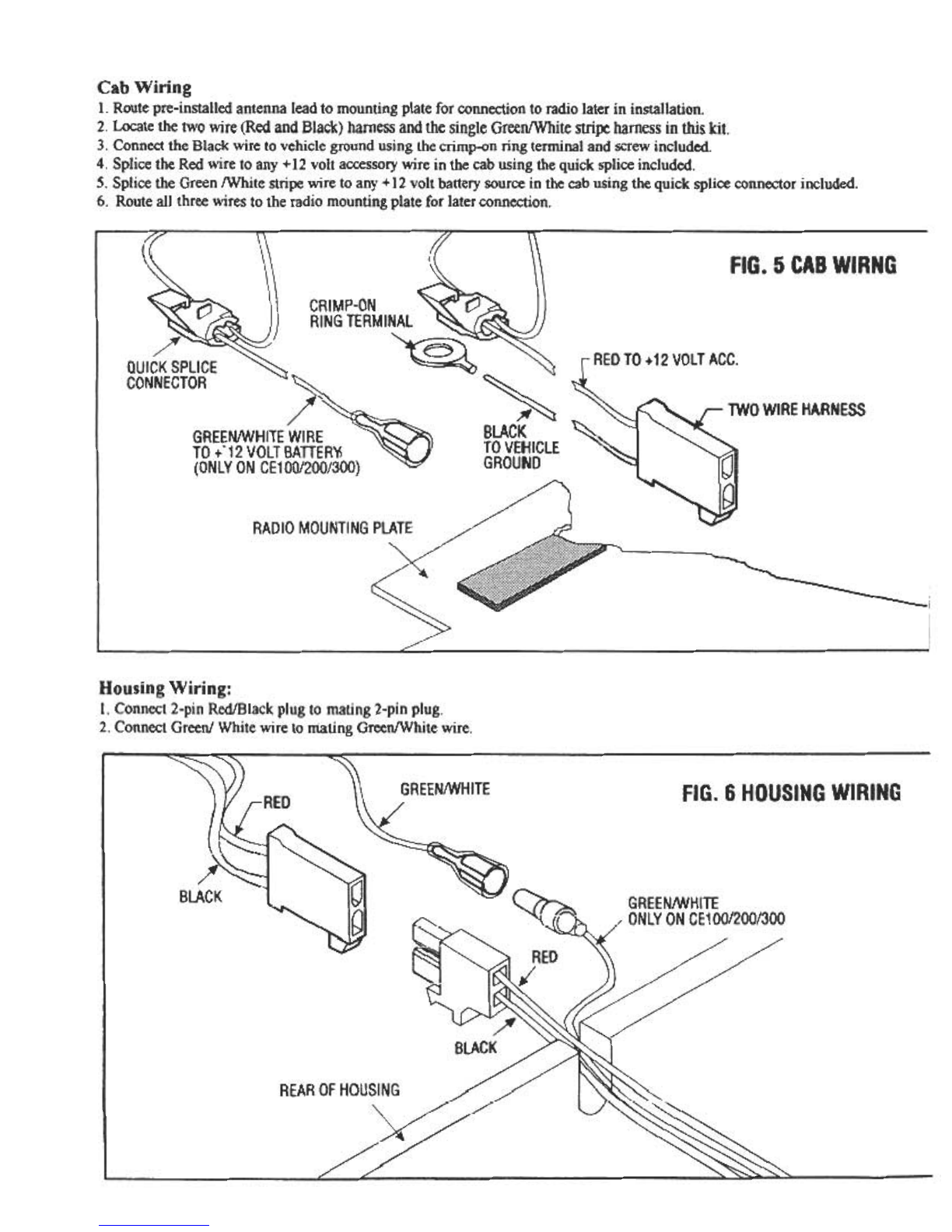
4. Wiring (See Fig. 5, 6)
A. Connect the antennacable to the socketon the rear of the radio.
B. Connect the Redpower lead to (+) 12volts.
C. Connect the Black ground lead to the vehicle's chassisground.
Caution: For usewith 12 volt negative ground system only, For 24 Volt Neg. ground, usewith converter.
Form No. 128-445~
Printed in U.S.A.
Fig. 1 Installation
I. Useuniversal template provided and locate on roof the desired mounting area.Observecautions for possible interference in
headliner or steel roof.
2. Drill two 5/16" dia. holesthrough the fiberglass roof cap,the steelroof and headliner making certain the drill is 900to the roof.
3. Enlarge the 5/16" holes in the fiberglass roof to 13/8" dia.
Warning -Only enlarge the two holes in the roof cap. Do not enlarge the holesin the steelroof or headliner.
4. Removethe inside headliner.
5. Assemblethe two selectedmounting bolts, cup washers,grommets,flat washersandjamb nuts to the steelroof using the wrench
provided. Make certain you apply sealant(not included) asshown.
6. Replaceheadliner.
7. Assemble radio mounting plate assemblyto bolt studsas shown.
8. Complete wiring.
9. Placehousing below radio plate assemblyand connect speakerwiring to radio wiring.
10.Securehousing using six screwsand washersprovided.
11.Insert the two 1 3/8" plugs in fiberglass headliner using sealantto insure water-proof seal..
12.SeeFig. 4 if installing CElOO/CE200/CE300.
Fig. 2 Installation
I. Useuniversal template provided and locate on roof the desired mounting area.Observecautions for possible interference in
headliner or steelroof.
2. Drill rn'o 5/16" dia. holesthrough the fiberglass roof cap,the steelroof and headliner making certain the drill is 900to the roof.
J. Removethe inside headliner.
4. Assemblethe two selectedmounting bolts, cupwashers,grommets, flat washersandjamb nuts to the steelroof using the wrench
provided. Make certain you apply sealant(not included} asshown.
5. Replaceheadliner.
6. Assemble radio mounting plate assemblyto bolt studsasshown.
7. Complete wiring.
8. Place housing below radio plate assemblyand connect speakerwiring to radio wiring.
9. Securehousing using six screwsand washersprovided.
IO.SeeFig. 4 if installing CEI00/CE200/CEJOO.
Fig. 3 Installation
I. Useuniversal template provided and locate on roof the desired mounting area.Observecautions for possible interference in
headliner or steelroof.
2. Drill two 5/16" dia. holesthrough the fiberglass roof cap,the steelroof and headliner making certain the drill is 90°to the roof.
3. Assemblethe two selectedmounting bolts, cupwash~rs,grommets, flat wa$hersandjamb nuts to the steelroof using the wrench
provided. Make certain you apply sealant(not included) asshown.
4. Assemble radio mounting plate assemblyto bolt studsasshown.
5. Complete wiring.
6. Placehousing below radio plate assemblyand connect speakerwiring to radio wiring.
7. Securehousing using six screwsand washersprovided.
8. SeeFig. 4 if installing CElOO/CE200/CE300.
Fig. 4 Installation
1.For figure I installation: Follow steps 1-11then refer to Fig. 4 and follow instructions below it.
2. For figure 2 installation: Follow steps 1-9 then refer to Fig. 4 and follow instructions below it.
3. For figure 3 installation: Follow steps 1-7then refer to Fig. 4 and follow instructions below it.
Figure 4 Installation: Only for CElOO/CE200/CE300
I. The entire housing and mounting plate (lessradio) should now besecuredto the roof asshown in Fig. 4
2. Insert mounting sleeveinto housing opening and bend all tabsoutward to secureit.
3. Reachthrough opening to accessradio wimg connector and plug into radio.
4. Reachthrough opening to accessantennalead and plug into radio.
5. Pre-testradio.
6. Slide radio into housing until locked in place.
FIG. A FIBERGLASS CAP ROOF
(CROSS SECTION OF ROOF)
RBERGLASSROOFCAP STEELROOF
:":,.:;:c;:;:;c:;,,;;.:c:.:'ii:::i FIG. A DISASSEMBLY:
AIRGAP
AIR GAP 1. Remove molded inside headliner prior
to installation
2. Do not remove the fiberglass roof cap
LMOLDED HEADLINER See F1g. 1. for Installation
FIG. B STEEL ROOF WITH HEADLINER
{CROSS SECTION OF ROOF)
FIG. B DISASSEMBLY:
1. Remove molded inside headliner prior
to installation
Note: If the air gap (space) between the
steel roof and the headliner is less
than 1/4" , refer to Fig. C
See Fig. 2 for Installation
FIG. C STEEL ROOF ONLY
(CROSS SECTION OF ROOF)
r; STEEL ROOF FIG. B DISASSEMBLY:
1. If the roof has an inside headliner that
is either flush or has an air gap of less
than 1/4" , do not remove the headliner
L NOTE: SOME OF THESE TYPES
OF ROOFS HAVE A HEADLINER
THAT IS GLUED TO INSIDE
OF THESE OF THE ROOF (NO
GAP IS IN RG. C)
See FIg. 3 for Installation
FIG. 1. INSTALLATION
WRENCH(INCLUDED) ~
-
/
/
~I/ STEEL CUP WASHERS
MOUNTING BOLT (SELECT LENGTH """"
NEEDE FROM CHOICE OF LENGTHS ,..,..
INCLUDED) I/r~MMEIS
---
DRILL 5/16. ~DIA. HOLES PER
TEMPLATE -;--- -
--
APPLY A BEAD OF
SEALANT AROUND
BOTH SIDES
OF HOLES
/
--
/
~
~ FLAT WASHERS
~..- JAM NUTS (TIGHTEN ARMLY)
~
~~
I
STEEL PLATE
~
USE THESE HOLES
FOR CASE 580K /
./
USE THESE HOLES /
FOR ALL OTHER EQUIPMENT ~
~
~
BLACK WASHERS
(6 PCS.) , ---
~
~
,,
,,TRIMPLATE
#6 BLACK SCREWS
(6 PCS.) PLASTICHOUSING ~==--
~0
0..,.. RADIO SHAFT NUTS
, (INSERT AFTER
""' INSTALLATION IS
COMPLETED) USE
I SEALANT TO INSURE
A LEAK-FREE SEAL
~
~.J
FIG. 3 INSTALLATION
WRENCH (INCLUDED)
~
/ STEEL CUP WASHERS
G RUBBER GROMMETS
MOUNTING BOLT (SELECT LENGTH ' INEEDE FROM CHOICE OF LENGTHSINCLUDED)
~
DRILL 5/16"
DIA. HOLES PER
TEMPLATE I
~
APPLY A BEAD OF SEALANT ~ FLAT WASHERS
AROUND BOTH SIDES ~ -
OF HOLES ~..- JAM NUTS (TIGHTEN RRMLY)
~~~
~c
STEEL PLATE ~ ~ ~
~~
,,)
~
---:
J--:-:""
USE THESE HOLES
FOR CASE 580K ~
USE THESE HOLES /
FOR ALL OTHER EQUIPMENT
~~
BLACK WASHERS
(6 PCS.)
~
#6 BLACK SCREWS
(6 PCS.) TRIMPLATE
PLASTICHOUSING 0
0~ RADIO SHAFT NUTS
Cab Wiring
I. Route pre-installed antenna lead to mounting plate for connection to radio later in installation.
2. Locate the two wire (Red and Black) harnessand the single Green/White stripe harnessin this kit.
3. Connect the Black wire to vehicle ground using the crimp-on ring terminal and screw included.
4. Splice the Red wire to any +12volt accessorywire in the cabusing the quick splice included.
5. Splice the Green /White stripe wire to any +12volt battery sourcein the cabusing the quick splice connector included.
6. Route all three wires to the radio mounting plate for later connection.
(FIG. 5 CABWIRNG
CRIMP-ON
RINGTERMINAL
~REDTD +12 VOLTACC.
QUICKSPLICE
CONNECTOR
~
BLACK ~
TOVEHICLE
GROUND
/"
GREEN/WHITEWIRE
TO+'12 VOLTBATTER~
(ONLYONCE100/200/300)
"',,"~
RADIOMOUNTINGPLATE
~;
Housing Wiring:
I. Connect 2-pin Red/Black plug to mating 2-pin plug.
2. Connect Green/ White wire to mating Green/White wire.
GREEN/WHITE FIG. 6 HOUSINGWIRING
RED
1,,--:
/~
BLACK I
~GREEN/WHITE
ONLYONCE10012001300
~RED
/
BLACK
REAROFHOUSING

This manual suits for next models

3

Other Audiovox Car Speakers manuals

Audiovox SW-50 User manual

Audiovox

Audiovox SW-50 User manual

Audiovox Prestige PST-692 Installation instructions

Audiovox

Audiovox Prestige PST-692 Installation instructions

Audiovox Prestige PS-2351 Operating instructions

Audiovox

Audiovox Prestige PS-2351 Operating instructions

Audiovox Prestige PS-2461 Operating instructions

Audiovox

Audiovox Prestige PS-2461 Operating instructions

Audiovox XS User manual

Audiovox

Audiovox XS User manual

Audiovox JX240 User manual

Audiovox

Audiovox JX240 User manual

Audiovox 6"x 9" User manual

Audiovox

Audiovox 6"x 9" User manual

Audiovox Prestige PST-52 Installation instructions

Audiovox

Audiovox Prestige PST-52 Installation instructions

Audiovox JPW104 User manual

Audiovox

Audiovox JPW104 User manual

Popular Car Speakers manuals by other brands

Rockford Fosgate Punch Aeroport RP9314 Installation & operation manual

Rockford Fosgate

Rockford Fosgate Punch Aeroport RP9314 Installation & operation manual

MB QUART EXP Series installation manual

MB QUART

MB QUART EXP Series installation manual

MB QUART MBQT-STG2-RAD-1 installation instructions

MB QUART

MB QUART MBQT-STG2-RAD-1 installation instructions

MB QUART Premium PWE 130 installation manual

MB QUART

MB QUART Premium PWE 130 installation manual

MB QUART Reference RTE 20 installation manual

MB QUART

MB QUART Reference RTE 20 installation manual

Power bass S-50C Application guide

Power bass

Power bass S-50C Application guide

MB QUART Car Tweeter DTK-30 installation manual

MB QUART

MB QUART Car Tweeter DTK-30 installation manual

Eton UG VW-T5 F 3.1 installation instructions

Eton

Eton UG VW-T5 F 3.1 installation instructions

Autotek ATS8 instruction manual

Autotek

Autotek ATS8 instruction manual

JVC CS-XV520 instructions

JVC

JVC CS-XV520 instructions

Hifonics BZE65C Quick start installation guide

Hifonics

Hifonics BZE65C Quick start installation guide

Pioneer TS-A633P manual

Pioneer

Pioneer TS-A633P manual

SSV Works RG4-5KRC manual

SSV Works

SSV Works RG4-5KRC manual

JVC CS-VS607 instructions

JVC

JVC CS-VS607 instructions

Kenwood KFC-1065 Service manual

Kenwood

Kenwood KFC-1065 Service manual

JBL CS205E owner's manual

JBL

JBL CS205E owner's manual

Sony XS-GF6932X Installation/connections

Sony

Sony XS-GF6932X Installation/connections

Rockford Fosgate T110D2 Installation & operation guide

Rockford Fosgate

Rockford Fosgate T110D2 Installation & operation guide

manuals.online logo
manuals.online logoBrands
  • About & Mission
  • Contact us
  • Privacy Policy
  • Terms and Conditions

Copyright 2025 Manuals.Online. All Rights Reserved.