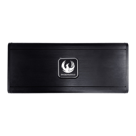
Audioxtra axis XT1D User manual

XT1D
MONOBLOCK CLASS D
DIGITAL POWER AMPLIFIER
XT4D
4 CHANNEL CLASS D
DIGITAL POWER AMPLIFIER
INSTALLATION MANUAL

FEATURES & SPECIFICATIONS
XT1D
- Max Power: 1880W (43.4V)
- Output Power @ 14.4V 4Ohm, 1% THD: 1 x 400W RMS
@ 14.4V 2Ohm, 1% THD: 1 x 700W RMS
- THD Continuous @ 4Ohm/100Hz: 0.5%
- Efficiency @ 4Ohm/100Hz: 93%
- S/N Ratio @ 4Ohm/100Hz: 99dB
- High/Low Level Input Conversion
- Input Sensitivity: 0.2 - 8V
- Dampening Factor @4Ohm: 142
- Low pass Crossover: 30 - 200Hz
- Subsonic Filter: 10 - 60Hz
- Bass Boost Gain: 0 - 12dB @ 45Hz
- 2 Ohm Stable
- Power Supply: 8 - 16V DC
- Fuse Rating: 2 x 25A
- Dimensions: 170 x 162 x 51mm (Chassis)
170 x 191 x 51mm (Including Terminals)
- Weight: 1.825 kg
- Includes: Remote Volume Controller
RCA Fly Lead for High Level Input
Installation Accessories
XT4D
- Max Power: 800W (28.4V) (1 channel mode)
- Output Power @ 14.4V 4Ohm, 1% THD: 4 x 75W RMS
@ 14.4V 2Ohm, 1% THD: 4 x 115W RMS
@ 14.4V 4Ohm, 1% THD: 2 x 240W RMS
- THD Continuous @ 4Ohm/1KHz: 0.2%
- Efficiency @ 4Ohm/1000Hz: 85%
- S/N Ratio @ 4Ohm/1KHz: 90dB
- High/Low Level Input Conversion
- Input Sensitivity: 0.2 - 8V
- Dampening Factor @4Ohm: 105
- Low Pass Crossover: 50 - 500Hz
- Hi Pass Crossover: 50 - 500Hz
- Bass Boost Gain: 0 - 12dB @ 45Hz
- 2 Ohm Stable
- Power Supply: 8 - 16V DC
- Fuse Rating: 1 x 30A
- Dimensions: 170 x 204 x 51mm (Chassis)
170 x 244 x 51mm (Including Terminals)
- Weight: 2.21 kg
- Includes: Rear Channel Remote Volume Controller,
RCA Fly Leads for High Level Input
Installation Accessories
2

XT4D
XT1D
3
RCA (LOW LEVEL) INPUT CONNECTION
Both amplifiers have RCA input connectors that can be used for low level inputs and hi level
inputs (Using the RCA Fly Lead/s included):
For low level input (RCA output from Head Unit)
Connect the left & right RCA output from the Head Unit to the left and right RCA inputs of the amplifier.
Adjust the Input level (Gain) on the amplifier to the same output level of the Head Unit for distortion
free sound e.g. if the Head Unit has 5volt output, adjust the amplifiers "Gain" to match the 5volt signal.
This is done by using an Oscilloscope.
INPUT
CH1 REMOTE
GAIN S.SONIC LPF BASS
8V 0.2V 10Hz 60Hz 30Hz 200Hz 0dB 12dB
CH2
HEAD UNIT Wired
Remote Volume Control
INPUT Channel 1/2 Channel 3/4 INPUT
CH1 GAIN X-OVER REMOTE X-OVER GAIN CH3
8V 0.2V
FULL LPF
50Hz 500Hz 50Hz 500Hz
LPF FULL
HPF HPF
8V 0.2V
CH2 CH4
Wired
Remote Volume Control
HEAD UNIT

SPEAKER (HIGH LEVEL) INPUT CONNECTION
For hi-level input (speaker wire output from Head Unit):
•Connect only the + Positive speaker wire from the Head Unit's left channel to the "+" left RCA Fly Lead
•Connect only the + Positive speaker wire from the Head Unit's right channel to the "+" right RCA Fly Lead
•Solder the positive speaker wire to the positive (conductor) of the RCA Fly Lead and then insulate, using
heat shrink for best results. Be sure to insulate (or tape back) "-" negative wires that are not being used.
Adjust the Input level (Gain) on the amplifier to the same output level of the Head Unit for distortion free sound
e.g. if the Head Unit has 5volt output, adjust the amplifiers "Gain" to match the 5volt signal. This is done by
using an Oscilloscope.
4
XT1D
INPUT
CH1 REMOTE
GAIN S.SONIC LPF BASS
8V 0.2V 10Hz 60Hz 30Hz 200Hz 0dB 12dB
CH2
Wired
Remote Volume Control
RCA HEAD UNIT
FLY LEAD +
(Included)
+X
XT4D X
INPUT Channel 1/2 Channel 3/4 INPUT
CH1 GAIN X-OVER REMOTE X-OVER GAIN CH3
8V 0.2V
FULL LPF
50Hz 500Hz 50Hz 500Hz
LPF FULL
HPF HPF
8V 0.2V
CH2 CH4
Wired
Remote Volume Control
RCA
FLY LEAD
Front Left Rear Left
+
(Included)
+X
X
-
Front Right Rear Right
HEAD UNIT
+
-
+
-
+
-
+
-
X
+X
+
+
-
+

GND REM B+
FUSE
POWER INPUT
PRT
PWR
POWER CONNECTION
+12V Power
Connect the +12V terminal of the amplifier to the + terminal of the battery. Use the same diameter
cable for ground. Ensure an in-line fuse holder is installed approximately 300 or 400 mm from the
positive battery terminal.
GROUND
Connect the GND (ground) cable to the vehicle chassis.
Keep this cable as short as possible (less than 500 mm).
Ensure that the connection to the chassis is rust free and clear of paint or corrosion.
REMOTE
Connect the REM terminal of the amplifier to the amplifier trigger wire of the head unit using 12 or 16
ga cable.
First connect the ground cable securely to vehicle's chassis. Then connect +12V
circuit and finally the remote connection. The +12V cable must always be fused
near the battery for protection against possible damage. When replacing a power
fuse, always replace it with a fuse of the same value.
Caution
to REMOTE Turn-on
from HEAD UNIT
GROUND
HEAD UNIT
To +12V DC
BATTERY
GROUND
XT1D/XT4D
5

ch A ch B
GND RE M B+
FUSE
POWER INPUT
PRT
PWR
SPEAKER OUTPUT
2-4 Ohm Load
+
-
SUBWOOFER
(2-4 Single Voice Coil)
2. Dual Voice Coil
!Caution
This amplifier cannot function in a Bridged Mode.
Use the amplifier in MONO mode only as shown above.
ch A ch B
GND RE M B+
FUSE
POWER INPUT
PRT
PWR
SPEAKER OUTPUT
SUBWOOFER x 2
2 Ohm Load
+
-
+
-
(4 Single Voice Coil)
ch A ch B
GND RE M B+
FUSE
POWER INPUT
PRT
PWR
SPEAKER OUTPUT
2 Ohm Load
SUBWOOFER
+
-
+
-
(4 Dual Voice Coil)
SPEAKER CONNECTION
XT1D
1. Single Voice Coil
6

7
PRT
PWR
CH2/R CH1/L
CH4/R CH3/L
SPEAKER
OUTPUT
CH1/2 BRIDGE
CH1/L CH2/R
CH3/4 BRIDGE
CH3/L CH4/R
PRT
PWR
CH2/R CH1/L
CH4/R CH3/L
SPEAKER
OUTPUT
CH1/2 BRIDGE
CH1/L CH2/R
CH3/4 BRIDGE
CH3/L CH4/R
PRT
PWR
CH2/R CH1/L
CH4/R CH3/L
SPEAKER
OUTPUT
CH1/2 BRIDGE
CH1/L CH2/R
CH3/4 BRIDGE
CH3/L CH4/R
4-Channel (Stereo)
3-Channel (Tri Mode)
Speaker Impedance
4~8 ohms
CH2
CH4
Speaker
Impedance
2~8 ohms
Speaker
Impedance
4~8 ohms
CH1-MONO
SUBWOOFER
CH2-MONO
SUBWOOFER
CH1
CH3
CH2
CH1
Speaker Impedance
2~8 ohms
CH3-MONO
SUBWOOFER
XT4D
SPEAKER CONNECTION
2-Channel (Bridged)

TROUBLE SHOOTING
PROTECTION LED LIGHTS UP WHEN AMPLIFIER IS POWERED ON
FUSE BLOW
OVERHEATING
Check the speaker impedance.
Check speakers for short-circuits.
Check if there is good airflow around the amplifier.
Check if a good ground connection is present and check speakers for short-circuits.
Disconnect all RCA inputs from the amplifier. If hissing / engine noise disappears,
replace the RCA connectors and re-check. Then check the source unit driving
the amplifier.
DISTORTED SOUND /
Check if the input level control has been set to match the output level of the unit.
Check the volume of head unit.
Check speakers for short-circuits.
Check if crossover frequencies have been properly set.
HISS-ENGINE NOISE
Check the value of minimum speaker impedance.
Check for short-circuits on power cable and vehicle chassis.
This power amplifier has in-built protection features to prevent damage. If the unit senses excessive
heat, short circuit or overload, the protection LED will light up and the system will shutdown. Prior to
checking the wiring for faults, turn all level controls down and turn power off. If the amplifier shuts
down due to excessive heat, the protection LED will not light up. In this case, simply allow the
amplifier to cool down. Before removing your amplifier, refer to the troubleshooting guidelines below.
Always test the speakers and their wires first.
AMPLIFIER DOES NOT POWER UP
Check if at least +12V DC exists at the battery power terminal.
Check if at least +13.8V DC is present on the remote terminal.
Check if a good ground connection is present. Check all fuses.
Check if protection LED is lit.
Check if remote wire is connected to remote turn-on wire of head unit.
Check if speaker wires are short-circuited.
Remove speaker wires and reset the amplifier. If protection LED still lights up,
then the amplifier is faulty.
8

9
NOTES

WARRANTY
Congratulations on your purchase of a quality Mobile Entertianment System! You’re joining
thousands of satisfied customers who enjoy & experience the benefits of the products we
distribute. In the unlikely event that some technical difficulty arises with your purchase, be
assured that we are most anxious to see that the problem is quickly rectified to your
satisfaction. Please familiarise yourself with the following simple conditions of our warranty.
This warranty covers faults through component failure or failure of the product to operate in
accordance with published specifications. Product failure as a result of unreasonable
environmental conditions, accident, misuse, improper installation, unauthorised repair, vehicle
electrical or wiring faults or neglect etc, will not be covered by this warranty. Removal and
installation costs, if any, would be paid by the owner as well as any freight or postage costs of
transporting the product to AudioXtra. AudioXtra shall not be liable or responsible for any loss
of use of this product or any form of consequential loss.
CONSUMER WARRANTY
This product is warranted by AudioXtra International Pty Ltd to be free from defects in
materials and workmanship under NORMAL USE for a period of TWENTY FOUR MONTHS
from the date of purchase.
WITHIN 30 DAYS OF PURCHASE DATE: Please return the unit for replacement to our
National Service Centre or the Retailer from where you made the purchase. All accessories
must be included. Proof of purchase date
Our goods come with guarantees that cannot be excluded under the Australian Consumer Law.
You are entitled to a replacement or refund for a major failure and for compensation for any other
reasonably foreseeable loss or damage. You are also entitled to have the goods repaired or replaced
if the goods fail to be of acceptable quality and the failure does not amount to a major failure.
must accompany the products.
AFTER 30 DAYS OF PURCHASE DATE: Warranty repair and service is carried out by our
National Service Centre. Repair and service will be carried out at no cost to the owner if proof
of ownership and the date of purchase can be verified to the satisfaction of the authorised
centre concerned with this repair. This proof should take the form of either:
a) The warranty card accompanying this product, stamped and dated by the dealer.
b) A Tax Invoice or Receipt showing full details of original vendor, purchaser, model
number and serial number.
COMMERCIAL WARRANTY: A product used in or associated with a commercial
application will carry a limited SIX MONTH warranty. An abnormal commercial application is
one where usage, dust, vibration, heat/cold and other environmental conditions exist at an
extreme level.
Model Number: Serial Number:
Dealer Name: Date of Purchase: / /
Dealer Address:
www.audioxtra.com.au
Purchaser’s Name:
Invoice/Sales Docket no:
Purchaser’s Address:
National Service Centre:
10 STODDART ROAD, PROSPECT, SYDNEY NSW 2148 Australia
Telephone: (02)88419000Fax: (02)96361204
email: services@audioxtra.com.au
Please complete details below in the event of warranty service being required.
General Hints: To expedite service and prompt return of the equipment, please:
a) Clearly describe the fault in detail c) Include your return address
b) Safety and security pack the unit for transport d) Provide proof of purchase date as outlined above
XT1D/XT4D
This manual suits for next models
1
Table of contents
