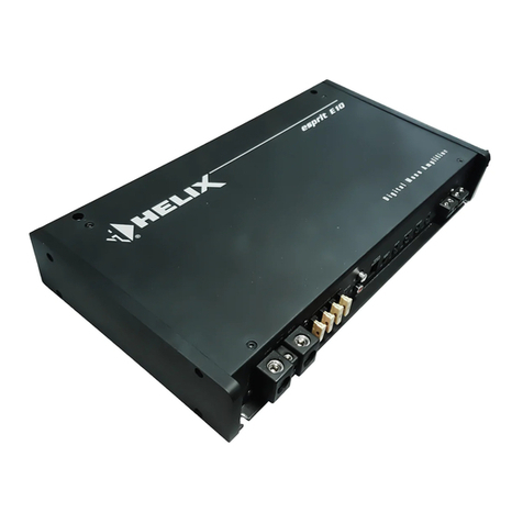
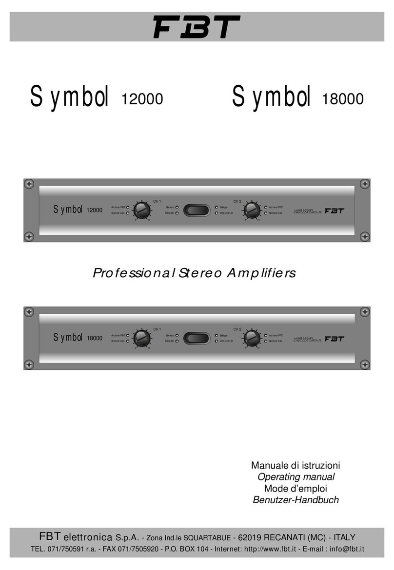
Fbt symbol 12000 User manual

FBT elettronica S.p.A. - Via Paolo Soprani 1 - Zona Ind.le Squartabue - 62019 RECANATI (MC) - ITALY
ENGLISH
Professional Stereo Amplifiers
Symbol 18000
Symbol 12000

2
1
2
2
2
3
3-4-5
6
6
7
8
8
9
10
11
1
INDEX
INTRODUCTION
Here are the “no-compromise” power amplifiers ! The new Symbol Power Amplifier series features two models based on a project design
targeted to obtain the most appropriate technical solutions to each and every need of signal amplification. The Symbol 12000 and the
Symbol16000grantstereopoweroutputofrespectively1500Wand2400Wperchannel(into2ohm).
All the steps followed for this project have been directed to the achievement of the maximum performance at every stage of application:
nothing has been saved from this “mission”! The application of Cascode circuits, of over-dimensioned final stages, of highly efficient
techniques such as the use of power supply at 2 or 3 steps and the highest capacity of electricity distribution.... The great quality of these
amplifiers guaranteed by the traditional FBT reliability and the rich equipment of technical features, place the Symbol 12000 and Symbol
18000tothetopoftherangeandconfirmFBT’stargettooffertherightaudiosolutiontoeveryneed.
TECHNICALCHARACTERISTICS:
>XLRconnectorsfor signalinputsandoutputs
>electronicallybalancedinputs
>poweroutputswith4-poleSpeakonconnectors
>facilityforoperation inparallel,monoorstereomodes
>powerlinethermalcut-outprotection
>independentprotectionsoneachchannel
>softstartfunction
>delayedactivationofoutputs
>dualloudspeakerprotectiontosafeguardagainstcontinuous
voltageonoutput(relay)
>short-circuitprotectiononoutputs
>SOAprotection
>clip limiter
>8dual-colourLED’sprovidingcomprehensiveat-a-glance
displayofoperatingmodes
>groundliftswitch
Introduction
Precautions
Unpacking
Warning
Front panel / Rear panel
Controls
Installation
Connections and power-up
Operating modes
Cables and connectors
Block diagram
Technical specifications
Technical glossary
Problems and solutions

2
PRECAUTIONS
UNPACKING
WARNING
!
|
|
|
<
CAUTION
RISK OF ELECTRIC SHOCK
DO NOT OPEN
TO REDUCE THE RISK OF ELECTRIC SHOCK
DO NOT REMOVE COVER (OR BACK)
NO USER SERVICEABLE PARTS INSIDE
REFER SERVICING TO QUALIFIED SERVICE PERSONNEL
TO REDUCE THE RISK OF FIRE OR ELECTRIC SHOCK
DO NOT EXPOSE THIS EQUIPMENT TO RAIN OR MOISTURE
- Readthismanualthoroughlyandobservethefollowingprecautionsbeforeworkingwiththeamplifier.
- Takecarenottospillliquidsontotheamplifieranddonotuseitinexcessivelyhumidconditions.
- Do not install the amplifier near heat sources or expose it to direct sunlight and do not install in dusty environments without suitable
protection.
- Donotobstructtheairintakeopeningsorthecoolingfans.
- Ensurethepowersupplyvoltagedoesnotexceedthevalueshownontherearpanel.
- Donotusetheamplifierunlessthemainscableandplugareinperfectcondition(replaceorrepairifnecessary).
- To safeguard against induced interference, do not install the amplifier next to transformers, television sets, RF transmitters, motors or
electricalpowersourcesofanydescription.
-Donotusesolventssuchasacetoneoralcoholtocleantheamplifierorthefinishandpanelletteringwillbedamaged.
- Do not connect output channels to input channels of other appliances and do not connect the CH1 OUT/CH2 OUT power outputs to any
loadotherthantherelativeinputconnectorontheloudspeakers.
- Donotconnectaudioinputstoelectricalpowersourcesofanytype.
- If a fault occurs, consult your nearest FBT service centre or a specialized audio equipment repair service. Do not attempt to repair the
amplifieryourself.
AlthoughallFBTproductsarecarefullyinspectedandtestedbeforeshipment,theycouldbedamagedintransit.Whenremovingthepackingmaterialinspect
theamplifiercarefullyforanysignofdamage.Informyourdealerimmediatelyiftheamplifierisdamagedonarrival.
Keepthe packingmaterial onhand sothat itcan bere-used ifthe amplifiermust beshipped toa servicecentre atany timeor inthe eventof resale.Note that
thistypeofequipmentholdsitsmarketvaluewell,provideditiskeptingoodconditionandcanbesuppliedinitsoriginalpackingtogetherwiththehandbook.

1 8
Symbol Active/PRT
Status/Clip
Ch 2
18000
ULTRA LINEAR
CASCODE CIRCUITS
0 10
Status/Clip
0 10
Active/PRT
Ch 1
Stereo Bridge
Parallel Ground Lift
3 5 7 3
2 4 6 2
1
STEREO
PARALLEL BRIDGE (CH1)
MADE IN ITALY
GND LIFT
ON ONOFF
Symbol 18000
LINE PROTECT
12
A
M
P
230 V
BRIDGE
OUTPUTS
2 OHM MIN. 4 OHM MIN. 2 OHM MIN.
Ch 1Ch 2
INPUTS
LINK LINK
Ch 1Ch 2
|
|
|
<
CAUTION
RISK OF ELECTRIC SHOCK
DO NOT OPEN
TO REDUCE THE RISK OF ELECTRIC SHOCK DO NOT
REMOVE COVER (OR BACK) NO USER SERVICEABLE
PARTS INSIDE REFER SERVICING TO QUALIFIED
SERVICE PERSONNEL
10 10 14 1511
9 9 1213
0 10
Active/PRT
Ch 1
3
FRONT PANEL
REAR PANEL
CONTROLS DESCRIPTION
1]Ch1/Ch2
Volumecontrolknob(Channel1andChannel2).Volumecontrolrangeisfrom0(nosignal)to10(fullvolume).
2]Active/PRT
Dual-colour LED: green indicates that the relative channel can operate correctly; red indicates that a protection
hastrippedandthechannelisonstandby.Protectionsmaytripforthefollowingreasons:
a) overheating: in this case the amplifier will resume normal operation after a brief interruption for cooling
purposes;at this point theLED changesfrom redto green, confirmingthat normaloperating statusof theSymbol poweramplifier hasbeen
restored.
b)inthecaseofafaulttheLEDwillremainredpermanentlyandtheamplifiermustbetakentoaservicecentre.
When the system ispoweredon the LED showsa redlight fora fewseconds, confirmingactivationof the automatic functionprotecting the
loudspeakersfrompowersurgesatstart-up.

OUTPUTS
2 OHM MIN. 2 OHM MIN.
Ch 1Ch 2
INPUTS
LINK LINK
Ch 1Ch 2
Stereo Bridge
Parallel Ground Lift
0 10
Status/Clip
Ch 1
4
3]Status/Clip
AmplifieroperatingstatusindicatorLED:
- greenindicatesthattheamplifierisfunctioningnormally
-redindicatesthatthesignalhasreachedthesaturationthreshold(clippinglevel)intheamplificationstage(inthis
casereducethevolumebymeansoftheCh1/Ch2(1)controls).
4]Stereo
ThisLEDilluminateswhentheSymbolpoweramplifierisfunctioninginstereomode(refertotheOperatingModeschapter).
5]Parallel
This LED illuminates when the Symbol power amplifier is functioning in parallel mode (refer to the
OperatingModeschapter).
6]Bridge
This LED illuminates when the Symbol power amplifier is functioning in bridge mode (refer to Operating
Modeschapter).
7]Groundlift
ThisLEDilluminatestoindicatethattheamplifierinputgroundisisolatedfromthegroundofconnectedequipment(seedescription-13-).
8] Power switch: In an audio system it is good practice to switch on power amplfiers last and switch them off first to avoid possible signal
peaks.
9]Ch1/Ch2inputs
Inputs with XLR connectors. The inputs are compatible with balanced signals from mixer outputs;
thetwo socketsforeachchannelare connectedinparallelso thatonecanbe used asaninputand
theothertopatchthesignaltoanotheramplifier.
10]Ch1/Ch2outputs
Outputs with Speakon connectors. For connecting loudspeakers to both amplification circuits.
Loudspeakers must have minimum impedance of 2 ohms and power handling of at least 1500W (Symbol
12000)or2400W(Symbol18000).
CONTROLS DESCRIPTION

BRIDGE
OUTPUTS
4 OHM MIN.
STEREO
PARALLEL BRIDGE (CH1)
GND LIFT
ON ONOFF
Symbol 18000
LINE PROTECT
12
A
M
P
230 V
5
11]Bridgeoutput
Mono output with Speakon connector. To connect a loudspeaker to both amplifier circuits in BRIDGE mode. The loudspeaker (or array of
loudspeakers connected in series/parallel) must have minimum impedance of 4 ohms and power handling
ofatleast3000W(Symbol12000)or4800W(Symbol18000).
12]Stereo-Parallel-Bridge
Three-position mode selector :STEREO-PARALLEL- BRIDGE (refer to Operating Modes chapter). Use this
selectoronlywhentheamplifierispoweredoff.
13]GNDLIFT
Switch for electrical isolation of the ground circuit from the earth circuit; this function can be used to
eliminatehumcausedbygroundloops.
14]Mainscable
Cablewithplugforconnectiontotheelectricalmainssupply(230V).
15]Lineprotect
Thermal cut-out to disconnect the power supply in the event of excess current absorpotion. To restore normal
operationoftheamplifierpresstheLINEPROTECTbutton.
CONTROLS DESCRIPTIONS

SIDE VIEW
A
6
INSTALLATION
CONNECTIONS & POWER UP
DONOTOBSTRUCTTHEAIRINTAKEOPENINGSOREXPULSIONGRILLES
SYMBOL amplifiersaredesignedforrack mounting(twostandard19"rackspaces) andaresuppliedwithfourfixing holeson
thefrontpanelflanges.
Therearpanelfeaturestwopins(A)designedtoengageintherack.
Theamplifierisequippedwithtwocoolingfansoperatingatvariablespeedinrelationtothetemperature.
Forefficientoperationoftheamplifier,ensurethattherearpanelairexpulsiongrillesareunobstructed.
Ifpossible,donotinstalltheamplifierinplacessubjecttodirectsunlight,hightemperatures,highlevelsofdustorhumidity.
Before connecting any other equipment, ensure that the amplifier is powered off and that the power supply data corresponds
tothespecificationsontherearpaneloftheSYMBOLpoweramplifier.
Makesurethevolumecontrolsaresetto0toavoidpossibledamagetotheloudspeakers.
Alsoensurethattheoperatingmodeselectorispositionedasrequired:STEREO,PARALLELorBRIDGE.
N.B.
POWEROFFTHEAMPLIFIERBEFORECHANGINGTHEPOSITIONOFTHEMODESELECTOR

STEREO
PARALLEL
BRIDGE
MIXER
SPEAKER CABINET
SPEAKER CABINET SPEAKER CABINET
SPEAKER CABINET
SPEAKER CABINET
MIXER
MIXER
STEREO
PARALLEL
BRIDGE
CH1
STEREOGND LIFT
BRIDGE
OUTPUTS
INPUTS
2 OHM MIN.
LINK LINK
4 OHM MIN. 2 OHM MIN.
PARALLEL
ON ON BRIDGE (CH1)
OFF
230 V LINE PROTECT
MADE IN ITALY
Ch 1
Ch 1
Ch 2
Ch 2
Symbol 18000
12
A
M
P
|
|
|
<
CAUTION
RISK OF ELECTRIC SHOCK
DO NOT OPEN
TO REDUCE THE RISK OF ELECTRIC SHOCK DO NOT
REMOVE COVER (OR BACK) NO USER SERVICEABLE
PARTS INSIDE REFER SERVICING TO QUALIFIED
SERVICE PERSONNEL
7
OPERATING MODES
When the input signal is stereo, use STEREO mode, selectable
on the rear panel. The left hand and right hand channel signals
must be connected to the amplifier INPUT1 and INPUT2
respectively. The signalwillbeamplifiedinstereoanddeliveredto
the OUT1 and OUT2 outputs; the left-right output balance can be
setusingthetwovolumecontrols.
For mono input signals use PARALLEL mode, selectable on the
rear panel. Mono signals should be connected exclusively to
INPUT1. The mono signal will be amplified by both channels and
delivered to outputs OUT1 and OUT2 at a volume that can be set
independentlyusingthetwovolumecontrols.
Whenworking with a mono input and singleloudspeaker line,you
can use the entire power available from the two output stages by
selecting BRIDGE mode on the rear panel. The signal must be
connected exclusively to INPUT1. The signal will be delivered to
the BRIDGE OUTPUT and amplified with double the available
powerwithrespecttothenormaltypeofconnection.

2
13
2
131+
2+
2- 1-
1+
2+
2- 1-
level
level
PROTECT OUT
BRIDGE
clip OUT 2
clip OUT 1
AUX
AUX
fan
fan
POWER AMP
BOOSTING
POWER SUPPLY
BOOSTING
POWER SUPPLY
POWER AMP
CH2
CH1
BRIDGE
PARALLEL
STEREO
SW
POWER
SUPPLY
8
CABLES & CONNECTORS
BLOCK DIAGRAM
12 21
33
Wirings side
Connections side
1. Massa Schermo (Ground) 2. Fase + Caldo (Hot) 3. Fase - Freddo (Cold)
XLR
1+ Positive
1 - Negative
1+
2+
2- 1-
SPEAKON
Alwaysusetopqualitycablesandconnectorswhenconnectingtheamplifieroutputtotheloudspeakersandtheinputstoamixer.
Check cables and connectors before powering on the amplifier; if cables and connectors are damaged, they must be replaced or properly
repairedbeforeusingtheamplifier.

TECHNICAL SPECIFICATIONS
Continuous power both channels driven
Continuous power Bridge mode
Impulsive power both channels driven
Impulsive power Bridge mode
Input sensitivity
Input impedance
Signal to noise ratio
THD
Frequency response
Max current output
Power consumption
Power supply
Protections
Cooling
Dimensions
Weight
Inputs
Slew rate
IMD
Symbol 18000
2x700W rms @ 8 ohm
2x1300W rms @ 4 ohm
2x1800W rms @ 2 ohm
3000W rms @ 8 ohm
4800W rms @ 4 ohm
6400W rms @ 2 ohm
2x800W rms @ 8 ohm
2x1500W rms @ 4 ohm
2x2400W rms @ 2 ohm
2x3200W rms @ 1 ohm
2600W rms @ 8 ohm
3600W rms @ 4 ohm
2 Veff
15k ohm
< 0.02%
< 0.05%
20Hz - 20kHz
80A eff
3500 VA
482 x 88 x 460
28
XLR-F
24
XLR-F
482 x 88 x 460
>40V/µS
>110dB “A” weighted
DC/Thermal/SOA/Soft Start
2 variable speed fans 2 variable speed fans
DC/Thermal/SOA/Soft Start
>110dB “A” weighted
>40V/µS
2x550W rms @ 8 ohm
2x900W rms @ 4 ohm
2x1300W rms @ 2 ohm
2000W rms @ 8 ohm
3000W rms @ 4 ohm
4000W rms @ 2 ohm
2x600W rms @ 8 ohm
2x1000W rms @ 4 ohm
2x1500W rms @ 2 ohm
2x2000W rms @ 1 ohm
1800W rms @ 8 ohm
2600W rms @ 4 ohm
1,7 Veff
15k ohm
< 0.02%
< 0.05%
20Hz - 20kHz
60A eff
2700 VA
W RMS
W RMS
W RMS
( 1 kHz-4ohm) 1W full power
1W full power
@ ±0.2 dB
kg
(WxHxD) mm
W RMS ( @THD< 0.05% 1kHz)
Symbol 12000
230 V 230 V
Symbol Active/PRT
Status/Clip
Ch 2
18000
ULTRA LINEAR
CASCODE CI RCUITS
0 10
Status/Clip
0 10
Active/PRT
Ch 1
Stereo Bridge
Parallel GroundLift
9
All power measurements made at 230V
All measurements made using AUDIO PRECISION equipment
Impulsive power measured in accordance with IHF method with 20mS bursts and REPETITION RATE 100mS

10
TECHNICAL GLOSSARY
Balanced and unbalanced - Aconnection is balanced when the signal is carried by two conductors (hot and cold) and a screening braid.
Thehot pin has thejob ofcarrying the in-phasesignal, whilethe coldone carriesthe samesignal, but outof phase.This methodenables to
make transmitted signals immune to electromagnetic interference even over long lines, thanks to the fact that when the two signals reach
the receiving device, they are algebraically subtracted one from the other, producing a new signal with twice the amplitude and eliminating
theinterferencealongitspath.
Ground- Electricalreferencepointfor asignaltravellinground acircuitoralonga cable.Thegroundgenerally hasavalueof zerovoltsand
is carried by audio cables by means of a metal sheath which also has the function of screening the signal (i.e. protecting it from external
electromagneticinterference.
Earth- The ground (or earth) in an electrical device is represented by the physical connection of the metal parts exposed to the user and a
cablein the powerplug (themiddle pin). By meansofthe mains powersupply, the ground cable(normallyrecognizable for itsyellow/green
colour)isconnectedtoametalpolehammeredintotheground,ofteninthebasementofthebuildingitself.
Theaimofthe groundsystemistodisperse inthegroundanycurrent whichintheeventof faultscouldelectrocuteauserwhentouchingthe
metal parts of the unit in question. The dispersion of energy is sometimes also used to eliminate any audio hum, which can be achieved by
meansofacapacitiveconnectionbetweenthesignalgroundandtheamplifierground,orevenaphysicalconnection.
Bridge- Indicates an electrical configuration of two power amplifiers that makes it possible to double the output power delivered to a single
loudspeaker line. In this mode the "bridge" connects the two power amplifiers to the same input signal but with a 180 degree reversal in
phase.Theloudspeakerisconnectedacrossthetwopositivebindingposts ontheamplifieroutput.Someamplifiersareabletoassumethis
configurationbymeansofaswitchanddedicatedmonooutput.
THD - Total Harmonic Distortion. This value indicates the relationship between the effective value of the spurious harmonics generated by
thesysteminquestionandtheeffectivevalueofthefundamentalsinewaveusedinthetest.THDisnormallyexpressedasapercentage.
Tone burst - The measurements carried out in laboratories to test amplifiers' power don't take into consideration the constant electrical
variations which a complex audio signal can have through time. Nowadays power is expressed in peak Watts (as far as the response of an
output stage with extremely brief transients states is concerned), musical Watts (which indicate the hypothetical power on a stable
sinusoidal signal) and RMS Watts (which measure the real power, but referred to a stable repetitive complex signal). The measurement
technique with Tone Burst signals is extremely significant as it cyclically recreates the possible dynamic range which a normal audio signal
canhave through time. This systemensures acontrol ofthe quality andcapacity ofthe output transistorsand aboveall ofthe power supply
containedintheamplifierbeingtested.
WattsRMS-Thisisameasurementwhichexpressestheeffectivevalueofthepower,i.e.therealamountofpowerwhichasystemisableto
deliver.RMS(RootMeanSquare) is the mathematical method usedto calculate the effective power: the square root of themean (average)
of the sum of the squares of the harmonics contained in the spectrum. The RMS Watts are exactly half the musical Watts and an eighth the
peak/peakWatts.

11
PROBLEMS AND SOLUTIONS
FLOW DIAGRAM LEGEND
FAULT TEST SOLUTION
YES YES
NO NO
The power ON
indicator doesn’t
light up
Does another unit
connected to the same
powersocket
switch on?
Check the socket’s
switches and electrical
connections
Has the fuse
on the rear panel
blown?
Contact an
authorized service
centre
Replace with
a new fuse
The loudspeakers
have a
background hum
Is the
GROUND LIFT
selector in the OFF
position?
Set the selector at ON
to avoid dangerous
ground loops
Avoid installation close to
electrical equipment which from
strong magnetic fields
(dimmers, transformers, etc.)
and use well screened (and if
possible balanced) connector
cables
YES
NO
The loudspeaker
output signal
distorted
YES
NO
Is the CLIP led lit red?
There’s an external
problem. Check the
quality of the signal
directly at the audio source
The signal being fed into the
amplifier must be lowered.
The volume controls enable
the input signal to be set at an
ideal level, indicated by
the green
colour of the CLIP led
YES YES
YES
NO
NO
NO
No sounds come
from the
loudspeakers and
PROTECT led is red
Is the amplifier
very hot?
Switching the
amplifier
off and on again after a few
minutes does the
fault still
occur?
A momentary overload
has occurred which has
tripped
the protection devices
Are the front panels
air vents and the fans’
outlets free from all
obstacles?
The heat produced by the
power circuits is dispersed by
the fans, which take in air
through the vents
on the front panel and
sent it out through rear panel
The amplifier’s final
stages
have burnt out.
Contact an authorized
assistance centre
When the final stage
reach excessively high
temperatures the
electronic
protections trip, putting the
system on standby

CODE 12195
Other manuals for symbol 12000
1
This manual suits for next models
1
Table of contents
Other Fbt Amplifier manuals

Fbt
Fbt Audio Contractor MMZ 8004 S User manual
Fbt
Fbt SA 2200 User manual

Fbt
Fbt Audio Contractor MMA 6120-TCD/MP3 User manual
Fbt
Fbt MPA 5120 User manual
Fbt
Fbt symbol 12000 User manual
Fbt
Fbt MA 6120T-6CD User manual

Fbt
Fbt MMA 3120 User manual

Fbt
Fbt MXA 3120 User manual
Fbt
Fbt M12 X4 User manual

Fbt
Fbt MXA 3240 User manual
