Fbt MMA 3120 User manual

INTEGRATEDAMPLIFIER
Istruzioniperl’uso
Instructionsforuse
Manueld’utilisation
Gebrauchsanleitung
Gebruiksaanwijzing
Instruccionesdeempleo
MMA3120
MMA3060
MMA3240

LaFBTsiriservaildirittodiapportaremodificheaidisegnieallecaratteristichetecnicheinqualsiasimomentoesenzapreavviso.
FBTreservetherighttomakechangestothedrawingsandtechnicalspecificationsatanytimeandwithoutnotice.
FBTseréserveledroitd’apporterdesmodificationsauxdessinsetcaractéristiquestechniquesàtoutinstantetsanspréavisaucun
FBTdasRechtvor,jederzeitundohneVorankündigungÄnderungenantechnischenZeichnungenund-Merkmalenvorzunehmem.
FBTbehoudtzijzichhetrechtvooropiedermomentzondervoorberichtdetekeningenentechnischeeigenschappenaan wijzigen
teonderwerpen.
FBTsereservaelderechodemodificarlosdibujosylascaracterísticastécnicassinpreavisoalguno.

1
TABLEOFCONTENTSSOMMARIO SOMMAIRE
SOMMAIRE
1.Descriptiongénérale
1.1Panneaufrontal .............................13
1.2Panneaupostérieur .......................13
2.Précautionsgénérales
2.1Installation .....................................14
2.2Alimentation ...................................14
2.3Conseilsdesecurite .......................14
3.Connexions
3.1Criteresgeneraux ..........................15
3.2Entréesmicro .................................15
3.3EntréesMIC/LINE ..........................15
3.4Entréesauxiliaires ..........................16
3.5Entréetéléphonique .......................16
3.6Sortie‘MusicOnHold’(MOH) ..........17
3.7Prioritémicroet
signald’annonce ............................17
3.8Sortiesdepuissance ......................18
3.8.1Systèmesàbasseimpédance .........18
-Calculdel’impédancesur
lesbranchementsensérie ...........18
-Calculdel’impédancesur
lesbranchementsenparallèle ......18
3.8.2Systèmesàtensionconstante ........19
-Calculdunombrede
diffuseurs(parlespuissances) .....19
-Calculdunombrede
diffuseurs (par les impedances)...19
3.9Sortieenregistreur/booster
etpriseegaliseur ...........................19
3.10 Selectiondezonesd’ecoute ...........20
4.Utilisationdel’appareil
4.1Miseenmarche ..............................21
4.2Controledevolumeprincipal ..........21
4.3Correctionacoustique ....................21
-Contrôletonalitébasses(BASS)...21
-Contrôletonalitéaigues(TREBLE).21
4.4Surchargeetprotection .................21
5.Caractéristiquestechniques... 22
Schémafonctionnel ........................... 33
TABLEOFCONTENTS
1.Generaldescription
1.1Frontpanel ......................................3
1.2Rearpanel .......................................3
2.Generalwarnings
2.1Installation .......................................4
2.2Powersupply ...................................4
2.3Safetynotes ....................................4
3.Connections
3.1Generalfeatures ..............................5
3.2Microphoneinputs ............................5
3.3MIC/LINEinputs ...............................5
3.4Auxiliaryinputs ................................6
3.5Telephoneinput ...............................6
3.6’MusicOnHold’output(MOH) ...........7
3.7Microphonepriority
andwarningsignal ...........................7
3.8Poweroutputs .................................8
3.8.1Low-impedancesystems ...................8
-Calculatingtheimpedance
valueinseriesconnections ............8
-Calculatingtheimpedance
valueinparallelconnection ............8
3.8.2 Constantvoltagesystems ...............9
-Determiningthenumberof
speakers (through power values)..9
-Determiningthenumberof
speakers(throughimpedance) .......9
3.9Recorder/boosteroutput
andequalisersocket ........................9
3.10 Selectingthelisteningareas ...........10
4.Operation
4.1Poweron .......................................11
4.2Mastervolumecontrol ....................11
4.3Acousticadjustment .......................11
-Basscontrol(BASS) .....................11
-Treblecontrol(TREBLE) ...............11
4.4Overloadingandprotection ............11
5.Technicalspecifications .......... 12
Blockdiagram ..................................... 33
SOMMARIO
1.Descrizionegenerale
1.1Pannellofrontale ..............................3
1.2Pannelloposteriore ..........................3
2.Avvertenzegenerali
2.1Installazione ....................................4
2.2Alimentazione ...................................4
2.3Notedisicurezza ..............................4
3.Connessioni
3.1Criterigenerali .................................5
3.2Ingressimicrofonici ..........................5
3.3IngressiMIC/LINE ............................5
3.4Ingressiausiliari ...............................6
3.5Ingressotelefonico ..........................6
3.6Uscita‘MusicOnHold’(MOH) ............7
3.7Precedenzamicrofonica
esegnaledipreavviso .....................7
3.8Uscitedipotenza .............................8
3.8.1Sistemiabassaimpedenza ...............8
-Calcolodell’impedenza
neicollegamentiinserie .................8
-Calcolodell’impedenza
neicollegamentiinparallelo ............8
3.8.2Sistemiatensionecostante ..............9
-Calcolodelnumero
didiffusori(tramitelepotenze) ......9
-Calcolodelnumero
di diffusori (tramite le impedenze)..9
3.9Uscitaregistratore/booster
epresaequalizzatore .......................9
3.10 Selezionedizoned’ascolto .............10
4.Usodell’apparecchio
4.1Accensione ....................................11
4.2Controllodivolumeprincipale .........11
4.3Correzioneacustica .......................11
-Controllotonibassi(BASS) ...........11
-Controllotoniacuti(TREBLE) ........11
4.4Sovraccaricoeprotezione ..............11
5.Caratteristichetecniche ......... 12
Schemaablocchi ............................... 33

2
INHOUDINHALTSANGABE SUMARIO
SUMARIO
1.Descripcióngeneral
1.2Panelfrontal ..................................23
1.2Paneltrasero .................................23
2.Advertenciasgenerales
2.1Instalación .....................................24
2.2Alimentación ..................................
2
4
2.3Notas para la seguridad..................24
3.Conexiones
3.1Criterios generales.........................25
3.2Entradasmicrofónicas ....................25
3.3EntradasMIC/LINE ........................25
3.4Entradasauxiliares ........................26
3.5Entradatelefónica .........................26
3.6Salidas’MusicOnHold’(MOH) ........27
3.7Precedenciamicrofónica
yseñaldepreaviso ........................27
3.8Salidasdepotencia ........................28
3.8.1Sistemasconbajaimpedancia ........28
-Cálculodelasimpedancias
enlasconexionesenserie ...........28
-Cálculodelasimpedancias
enlasconexionesenparalelo ......28
3.8.2Sistemasdetensiónconstante .......29
-Cálculodelnœmerodedifusores
(mediantelaspotencias) .............29
-Cálculodelnúmerodedifusores
(mediantelasimpedancias) ..........29
3.9Salidagrabadora/booster
ytomaecualizador .........................29
3.10 Seleccióndezonasdeescucha.......30
4.Usodelaparato
4.1Encendido ...................................... 31
4.2Controldevolumenprincipal ..........31
4.3Correcciónacústica ........................31
-Controltonosbajos(BASS) ..........31
-Controltonosagudos(TREBLE)...31
4.4Sobrecargayprotección ................31
5.Característicastécnicas ......... 32
Esquemadebloques .......................... 33
INHOUD
1.Algemenebeschrijving
1.2Frontpaneel ...................................23
1.2Achterpaneel .................................23
2.Algemeneaanwijzingen
2.1Installatie ......................................24
2.2Voeding ..........................................24
2.3Opmerkingenoverdeveiligheid ......24
3.Aansluitingen
3.1Algemenecriteria ...........................25
3.2Microfooningangen ........................25
3.3MIC/LINEingangen ........................25
3.4Hulpingangen .................................26
3.5Telefooningang ...............................26
3.6Uitgangen‘MusicOnHold’(MOH)....27
3.7Microfoonvoorrangen
waarschuwingssignaal ....................27
3.8Vermogensuitgangen ...................... 28
3.8.1Systemen met een lage impedantie.28
-Berekeningvandeimpedantie
bijserieschakeling ........................28
-Berekeningvandeimpedantie
bijparallelschakeling ....................28
3.8.2 Constantespanningssystemen .......29
-Berekeningvanhetaantal
klankverspreiders (via de kracht).29
-Berekeningvanhetaantal
klankverspreiders (via de impedanties)29
3.9Uitgangrecorder/booster
enaansluitingequalizer ..................29
3.10 Selectievanluisterzones ................30
4.Gebruikvanhetapparaat
4.1Aanzetten ......................................31
4.2Hoofdvolumeregeling .....................31
4.3Akoestischecorrectie .....................31
-Regelinglagetonen(BASS) .........31
-Regelinghogetonen(TREBLE)...31
4.4Overbelastingenbeveiliging ..........31
5.Technischekenmerken ........... 32
Blokschema ........................................ 33
INHALTSANGABE
1.AllgemeineBeschreibung
1.1Frontpaneel ...................................13
1.2Rückpaneel ....................................13
2.AllgemeineHinweise
2.1Installation .....................................14
2.2Einspeisung ....................................14
2.3Sicherheitsanweisungen .................14
3.Anschlüsse
3.1AllgemeineHinweise .......................15
3.2Mikrofoneingänge ..........................15
3.3EingängeMIC/LINE ........................15
3.4Hilfseingänge .................................16
3.5Telefoneingang ..............................16
3.6Ausgänge‘MusicOnHold’(MOH)....17
3.7Mikrofonvorrangund
Vorankündigungssignal ...................17
3.8Leistungausgänge ..........................18
3.8.1SystemmitniedrigerImpedanz .......18
-BerechnungderImpedanz
beiReihenschaltungen .................18
-BerechnungderImpedanz
beiParallelschaltungen ................18
3.8.2SystememitkonstanterSpannung..19
-Berechnungderlautsprecheranzahl
(durch die leistungen)...................19
-Berechnungderlautsprecheranzahl
(durch die impedanzen)................19
3.9AusgangAufnahmegerät/Booster
undBuchseEqualizer .....................19
3.10 AuswahlderKlangzone ..................20
4.GebraüchdesGerates
4.1Einschalten ....................................21
4.2SteuerungderHauptlautstärke ......21
4.3Tonkorrektur ..................................21
-Tiefenkontrolle(BASS) .................21
-Kontrollehohetöne(TREBLE) ......21
4.4ÜberlastungundSchutz .................21
5.TechnischeEigenschaften ...... 22
Blockschema ....................................... 33
.....

3
DESCRIZIONEGENERALE GENERALDESCRIPTION
1.1PANNELLOFRONTALE
[1] Selettoridellezone.
[2] Visualizzatoredellivellodiuscita.
[3] Spiad’accensione.
[4] Interruttoredirete.
[5] Controllodivolumegenerale.
[6] Controlliditono.
[7]Selettoreingressiausiliari.
[8]Controllolivelloingressoausiliario.
[9]Controllidilivelloingressi3e4.
[10]Controllidilivelloingressimicrofonici.
1.2PANNELLOPOSTERIORE
[11] Selettoredellatensionedirete.
[12] RegolazionelivellouscitaMUSICONHOLD.
[13] Uscitedilineaedipotenza(1W/8Ω)MUSICONHOLD.
[14] Ingressotelefonicobilanciato.
[15] Regolazionelivelloingressotelefonico.
[16]Presaperequalizzatoreesterno.
[17 ]ChimeON/OFF.
[18]Selettorimodalitàfunzionamentoingressi3e4.
[19] Morsettierapercontattodiprecedenza.
[20]Presadiaerazioneventoladiraffreddamento.
[21]Ingressimicrofonicibilanciati.
[22]IngressiMIC/LINE.
[23]Ingressiausiliari.
[24] Morsettieraperzoneselezionate.
[25] Morsettierauscitealtoparlanti.
[26]Morsettieraperalimentazioneesternaincorrentecontinua.
[27]Connessionetelaio.
[28]Spinadireteconfusibileincorporato.
1.1FRONTPANEL
[1] Zoneselectionswitches.
[2] Outputlevelindicator.
[3] ON/OFFsignallinglamp.
[4] Mainsswitch.
[5] Generalvolumecontrol.
[6] Tonecontrols.
[7]Auxiliaryinputsselectorswitch.
[8]Auxiliaryinputlevelcontrol.
[9]Inputs3and4levelcontrol.
[10] Levelcontrolformicrophoneinputs.
1.2REARPANEL
[11] Mainsvoltageselectorswitch.
[12] MUSICONHOLDoutputleveladjustment.
[13] MUSICONHOLDlineandpoweroutputs(1W/8).Ω
[14] Balancedtelephoneinput.
[15] Telephoneinputleveladjustment.
[16]Socketforanexternalequaliser.
[17]ChimeON/OFF.
[18]Inputs3and4modeselectorswitches.
[19] Terminalstripforprecedencecontact.
[20]Coolingfanairintake.
[21] Balancedmicrophoneinputs.
[22]MIC/LINEinputs.
[23] Auxiliaryinputs.
[24] Terminalstripforselectedzones.
[25] Loudspeakeroutputterminalstrip.
[26]TerminalstripforexternalDCpowersupply.
[27]Frameconnection.
[28]Mainsplugwithbuilt-infuse.
ZONE1ZONE3ZONE2ALL
OUTPUTLEVEL
POWER
MASTERVOLUME
10
0
TREBLE
0
+1010
BASS +1010101010101000000 INPUT5
AUXCD
INPUT3INPUT4MICRO1MICRO2
12
456910873
0
111215161718191314
202122232425262728
INPUT5INPUT4INPUT3MICRO2MICRO1
POWERIN
24VCOM50V70V100V
LINK
PRIORITY
+P
COMCOMCOMVINZ2Z3Z1
MOHOUTPUTTEL
1V1W GCOMHOT
8Ω
8Ω
600 Ω
FUSET6,3A
CONSUMPT.200W
CONSUMT.200W
AUXCD
PREOUT
PHANTOM
LINE MIC
PHANTOM
LINE MIC

4
AVVERTENZEGENERALI GENERALWARNINGS
2.2ALIMENTAZIONE
Questoapparecchioèpredispostoperilfunzionamentocontensionedi
retea230V–10%50/60Hz.¨possibileutilizzarel’apparecchioanche
conunatensionediretedi115V–10%50/60Hz;atalscopoè
necessarioportareilselettore[11 ]inposizione“115V”.
Gliamplificatoridella Serie5000 possono ancheesserealimentaticon
unasorgenteesternadicorrentecontinuacontensionedi24Vche
deveessereapplicata,rispettandolepolarità,airelativiterminalidella
morsettiera[26].Inaccordoconlenormativedisicurezza,l’interruttore
diaccensione[4]agiscesolosullatensionedirete.
Indotazioneall’apparecchioèfornitouncavodialimentazioneconfilo
diterra;ilterminalediterradellaspinadiretenondeveessererimosso
inalcuncaso.
Collegarelaspinadirete[28]dell’apparecchioallareteelettrica
utilizzandol’appositocavofornitoindotazione;assicurarsichelapresa
dicorrentesiadotatadicollegamentoditerraanormadilegge.
L’apparecchioèprotettodaduefusibili(vedipar.4.4).
2.3NOTEDISICUREZZA
Ogniinterventoall’internodell’apparecchio,qualelaselezionedialcuni
modid’usoolasostituzionedifusibili,deveessereeffettuatosoloda
personalespecializzato:larimozionedelcoperchiorendeaccessibili
particonrischiodiscosseelettriche.
Primadirimuovereilcoperchioaccertarsisemprecheilcavodiretesia
staccato.
Nelcasodiaccidentalecadutadiliquidisull’apparecchio,staccare
immediatamentelaspinadireteedinterpellareilcentrodiassistenza
FBTpiùvicino.
Laconnessioneditelaio[27]consentedicollegarealtreapparecchiature
perlasolafunzionedischermaturadeisegnaliabassolivello: questa
presanondeveessereutilizzataperilcollegamentodisicurezzadeltelaio
allaterra.
Fig.2.1.1
2.1INSTALLAZIONE
TuttigliapparecchiFBTsonocostruitinelrispettodellepiøsevere
normativeinternazionalidisicurezzaedinottemperanzaairequisiti
dellaComunitàEuropea.Peruncorrettoedefficaceusodell’apparecchio
èimportanteprendereconoscenzadituttelecaratteristicheleggendo
attentamentelepresentiistruzioniedinparticolarelenotedisicurezza.
Duranteilfunzionamentodell’apparecchioènecessarioassicurare
un’adeguataventilazione.Evitarediracchiuderel’apparecchioinun
mobileprivodiaerazioneodiostruirelefessurediventilazioneedin
particolarelapresad’ariaposterioredellaventoladiraffreddamento.
Evitareinoltreditenerel’apparecchioinprossimitàdisorgentidicalore.
Questoapparecchioèpredispostoperilmontaggioinmobilerackstandard
19”.
Siconsigliadiinterporreunpannellodiaerazionetraunapparecchioe
l’altro(vedifig.2.1.1).
2.1INSTALLATION
AllFBTequipmentismanufacturedinaccordancewiththemost
stringentinternationalsafetystandardsandincompliancewithEuropean
Communityrequisites.Inordertousetheequipmentcorrectlyand
effectively,itisimportanttobeawareofallitscharacteristicsbyreading
theseinstructionsandinparticularthesafetynotescarefully.
Whiletheequipmentisworking,itisnecessarytoprovideadequate
ventilation.Donotclosethisequipmentinsideanunventilatedcabinet
anddonotobstructtheairvents,inparticularnottheairintakeonthe
rearforthecoolingfan.
Donotkeeptheequipmentinthevicinityofsourcesofheat.
Thisequipmentcanbeequippedformountinginastandard19”.
Itisrecommendedthatyouplaceaventilationpanelbetweenone
pieceofequipmentandthenext(seeFigure2.1.1).
2.2POWERSUPPLY
Thisequipmentisdesignedforusewithamainsvoltageof230V–10%
50/60Hz.Itisalsopossibletousetheequipmentwithamainsvoltage
of115V–10%50/60Hz,howeverinthiscaseitisnecessaryto
positiontheselectorswitch[11 ]on“115V”.
Theamplifiersofthe 5000Series canalsobepoweredbymeansofan
externalDCpowersupplywithavoltageof24V,whichhastobeapplied
totheappropriateterminalsontheterminalstrip[ 26]payingattention
tothecorrectpolarity .Asrequiredundersafetyregulations,the
ON/OFFswitch[4]onlycontrolsthemainsvoltage.
Theequipmentissuppliedwithitsownpower-supplycable,whichis
equippedwithanearthingwire.Theearthterminalofthemainsplug
shouldneverberemovedunderanycircumstances.
Connectthemainsplug[28 ]oftheequipmenttothepowermainsusing
thecableincludedinthesupply.Makesurethatthepoweroutletis
equippedwithaconnectiontoearthinaccordancewiththelaw.
Theequipmentisprotectedbytwofuses(seepoint4.4).
2.3SAFETYNOTES
Anyactivitiesinsidetheapparatus,suchasselectingsomeofthe
operatingmodes,theinstallationofaccessoriesorthereplacement
offuses,mustbecarriedoutbyspecializedpersonnelonly:whenthe
coverisremoved,partsliabletocauseelectricshocksareexposed.
Beforeremovingthecover,alwaysmakesurethatthepowercord
hasbeendisconnected.
Intheeventthatliquidisaccidentallyspiltontotheapparatus,
disconnectthemainsplugimmediatelyandcontactthenearestFBT
ServiceCentre.
Thechassisconnection[27]maybeusedtoconnectotherequipment
onlyforthepurposeofshieldingthelowsignals: thissocketmaynot
beusedtoconnectthechassistoearthforsafetypurposes.
5
CONNESSIONI CONNECTIONS
3.1CRITERIGENERALI
Peruncorrettofunzionamentodell’apparecchioèopportunoosservare
alcunicriteridimassimanell’esecuzionedeicollegamenti:
•evitareilposizionamentodicaviedimicrofonisulmobile
dell’apparecchio.
•evitaredistenderelelineedisegnaleparalleleaquelledirete;
osservareunadistanzaminimadi30/40cm.
•posizionarelelineediingressoelelineediuscitadistantitraloro.
•posizionareimicrofonialdifuoridell’angolodiradiazionedeidiffusori
sonoriperevitareilfenomenodireazioneacustica(effettoLarsen).
3.2INGRESSIMICROFONICI
AllepreseXLR“MICRO1”e“MICRO2”[21]èpossibilecollegare
microfoniPASOditipodinamicoead elettreteconalimentazionephantom;
icollegamentiaquestepresesonoriportatinellaFig.3.2.1.
Ulterioripossibilitàdiconnessione,chesfruttanol’usodellamorsettiera
PRIORITY [19],sonoriportatealpar.3.7.
Ogniingressomicrofonicodisponediunpropriocontrollodilivello[ 10]
perdosareopportunamentel’ampiezzadeivarisegnali.
L’ingressomicrofonico“MICRO1”dispone,inoltre,dellafunzionedi
precedenzaautomatica(VOX): parlandoalmicrofonocollegatoaquesto
ingressoverrannoautomaticamenteammutolitigliingressi ausiliarie
l’ingresso“INPUT4”(seselezionato,vedipar.3.3);illivellodella soglia
diattivazionedelcircuitodiprecedenzaautomaticanonèdipendente
dallaposizionedelcontrollo“MICRO1”[10].
Gliingressimicrofonici[21]sonodotatidialimentazionePhantomper
microfonielettrete12/24V.
Incasosivolessedisinserirel’alimentazionePhantom,agiresuiponticelli
SW201 -SW202 situatisulcircuitoingressi(v edipar.2.3).
Fig.3.2.1
3.3INGRESSIMIC/LINE
Leprese“INPUT3”ed“INPUT4”[22]sonoconfigurabiliinmodo
indipendentecomeingressimicrofonici(conosenzaalimentazione
phantom)ocomeingressidilinea.Laselezionedellamodalitàèottenuta
tramiteideviatoriatreposizioni[18 ]:
•inposizioneMIC,siselezionalasensibilitàmicrofonicaconalimentazione
phantomdisattivata;
•inposizionePHANTOM,siselezionalasensibilitàmicrofonicaattivando
l’alimentazionephantom(permicrofonielettrete12/24V);
•inposizioneLINE,siselezionalasensibilitàdilinea.
ÉpossibileeffettuareilcollegamentosiaconspineditipoXLRmaschioche
conspinottojack1/4”.Icol legamentiaquestepresesonoriportati
nellaFig.3.2.1.
Ogniingressodisponediunpropriocontrollodilivello[9]perdosare
opportunamentel’ampiezzadeivarisegnali.
L’ingresso“INPUT4”puòessereassoggettatoomenoallaprecedenza
automatica(VOX)dell’ingresso“MICRO1” edallachiusuradelcontatto
diprecedenzaPRIORITY.Incasosivolessedisinserirequestafunzione,
agiresulponticello SW207 postosulcircuitoingressi(vedipar.2.3).
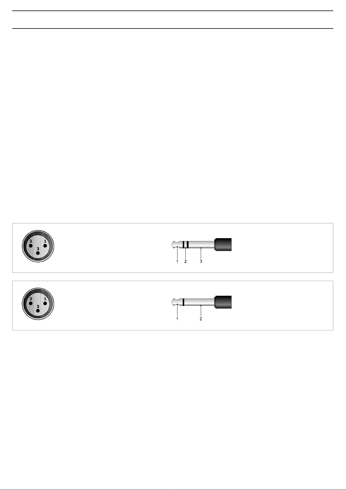
1=schermo/shield
2=segnale(latocaldo)/signal(hotside)
3=segnale(latofreddo)/signal(coldside)
1=segnale(latocaldo)/signal(hotside)
2=segnale(latofreddo)/signal(coldside)
3=schermo/shield
3.1GENERALFEATURES
Forproperunitoperation,usethefollowinginstructionswhenmaking
theconnections:
•Donotplacecablesormicrophonesontheunitcabinet;
•Donotlaysignallinesparalleltopowerlines;ensureaminimum
distanceof30/40cmbetweenthem;
•Keepinputlinesandtheoutputlinesfarapart;
•Keepthemicrophonesoutsidetheoperatingspanofthespeakersto
avoidacousticfeedback(Larseneffect).
3.2MICROPHONEINPUTS
ItispossibletoconnectPASOmicrophonesofthedynamicoroftheelectret
typewithaphantompowersupplytotheXLRsockets“MICRO1”and
“MICRO2”[21].
TheconnectionstothesesocketsareshowninFigure3.2.1.
Furtherpossibleconnectionsexploitingthe PRIORITY terminalstrip
[19]areindicatedunderpoint3.7.
Eachmicrophoneinputhasitsownlevelcontrol[10]sothatthe
amplitudeofthevariousdifferentsignalscanbesuitablyadjusted.
The“MICRO1”microphoneinputalsohasanautomaticpriority
function(VOX).Whenspeakingwiththemicrophoneconnectedtothis
input,theauxiliaryinputsand“ INPUT4”willbeautomaticallymuted
(ifselected,seepoint3.3).Thelevelofthethresholdforactivating
theautomaticprioritycircuitdoesnotdependonthepositionofthe
“MICRO1”control[10].
Themicrophoneinputs[21]haveaphantompowersupplyfor12/24V
electretmicrophones.Toexcludethephantompowersupply,use
jumpers SW201 and SW202 ontheinputcircuit(seepoint2.3).
3.3MIC/LINEINPUTS
The“INPUT3”and“INPUT4”sockets[22]canbeseparately
configuredasmicrophoneinputs(withorwithoutphantompowersupply)
oraslineinputs.
Themodesareselectedbymeansofthethree-positionswitches[18]:
•intheMICpositionthesensitivityofthemicrophonewiththephantom
powersupplyde-activatedisselected;
•inthePHANTOMpositionthesensitivityofthemicrophonewiththe
phantompowersupplyactivated(for12/24Velectretmicrophones)is
selected;
•intheLINEpositionthesensitivityofthelineisselected.
ItispossibletomaketheconnectionseitherwithmaleXLRplugsorwith
1/4”jacks.TheconnectionstothesesocketsareshowninFigure3.2.1.
Eachinputhasitsownlevelcontrol[9]soastobeabletoadjustthe
amplitudeofthevariousdifferentsignalssuitably.
“INPUT4”canbesubjectedorotherwisetoautomaticpriority(VOX)on
thepartofthe“MICRO1”inputandtoclosingofthePRIORITYcontact.
Intheeventthatyouwishtode-activatethisfunction,usejumper
SW207 situatedontheinputcircuit(seepoint2.3).
COLLEGAMENTOBILANCIATO-BALANCEDCONNECTION
1=schermoemassa/shieldand GND
2=schermoemassa/shieldand GND
3=segnale/signal
1=segnale/signal
2=schermoemassa/shieldand GND
COLLEGAMENTOSBILANCIATO-UNBALANCEDCONNECTION

6
CONNESSIONI CONNECTIONS
3.5INGRESSOTELEFONICO
L’apparecchioèpredispostoperilcollegamentoadunsistematelefonico
tramitelamorsettiera“TEL”[14].Taleingressoèbilanciatoa
trasformatore,possiedeunpropriocontrollodilivello-“ LEV.”[15 ]-edè
dotatodicircuitoVOXperladiffusionedeimessaggiconprioritàpiù
elevatarispettoaqualsiasialtroingresso.
L’ingressotelefonicoconsenteinoltreilcollegamentodell’apparecchioalle
basipreamplificate. Perquestoènecessariorimuovere
lospinottopentapolareDINdalcavodellabaseeconifilirealizzarei
collegamentiillustratiinfig.3.5.1.
IMPORTANTE :perquestotipodicollegamentoèINDISPENSABILE
chiuderetramiteunponticelloicontatti[G]e[COM]dellamorsettiera
“TEL”[14].
3.5TELEPHONEINPUT
Theequipmenthasprovisionsforconnectionofatelephonesystemby
meansofthe“TEL”terminalstrip[14].
Thisinputisbalancedbyatransformer,hasitsownlevelcontrol-“ LEV.”
[15 ]-andisequippedwithaVOXcircuitforbroadcastingmessageswith
ahigherprioritylevelthananyotherinput.
Thetelephoneinputalsoenablestheequipmenttobeconnectedtothe
pre-amplifiedbases.Todothis,itisnecessaryto
removethefive-poleDINplugfromthecableonthebaseandusethe
wirestomaketheconnectionsillustratedinFigure3.5.1.
IMPORTANT :ForthistypeofconnectionitisESSENTIALtoclosethe
contacts[G]and[COM]ofthe“TEL”terminalstrip[14]withajumper.
Fig.3.5.1
3.4INGRESSIAUSILIARI
Allepresephono“AUX”e“CD”[23]èpossibilecollegareduesorgenti
musicaliadaltolivello(lettoredicompactdisc,riproduttoreanastro,
sintonizzatore,radioricevitorepermicrofonisenzafilo,ecc.).
Ladoppiapresaconsenteunvelocecollegamentodellasorgente
all’amplificatoretramitecavettostereo:lamiscelazionedeiduecanali
destroesinistro(L/R)èrealizzatainternamente.
Laselezionedellasorgenteavvienetramitel’appositoselettore[7 ]posto
sulpannellofrontaledell’apparecchio.
Laregolazionedilivellodellasorgenteselezionatasieffettuatramiteil
controllo INPUT5 [8 ].
Lasorgenteselezionataèsoggettaall’ammutolimentosiaperprecedenza
automatica(VOX)degliingressi TEL eMICRO1 cheperlachiusuradel
contatto PRIORITY.
3.4AUXILIARYINPUTS
Itispossibletoconnecttwohigh-levelsourcesofmusic(CDplayer,tape
recorder,tuner,radio-receiverforwirelessmicrophones,etc.)tothe
“AUX”and“CD”[23]phonosockets.Thankstothefactthatthereare
twosockets,itiseasytoconnectthesourcerapidlytotheamplifierby
meansofastereocable:mixingofthetwochannels(leftandright-L/R)
iscarriedoutinternally.
Thesourceisselectedbymeansoftheselector[7]providedforthis
purposeonthefrontpaneloftheequipment.
Thelevelofthesourcethatisselectedcanbeadjustedbymeansofthe
INPUT5 control[8 ].
Thesourcethatisselectedissubjecttomutingbothasaresultof
automaticpriority(VOX)ofthe TEL and MICRO1 inputsanddueto
closingofthe PRIORITY contact.
.SOPOVACELBACAREITTESROMPIRTSLANIMRETELANIMRETLANIMRET
1OMREHCSDLEIHS
"LET"
[G]
2ORENKCALB[MOC]
3OCNAIB ETIHW[TOH]
4OSSOR DER"YTIROIRP"[+]
5EDREV NEERG[P]
INPUT5INPUT4INPUT3MICRO2MICRO1
POWERIN
24VCOM50V70V100V
LINK
PRIORITY
S.p.A.-ITALY
COMCOMCOMVINZ2Z3Z1
MOHOUTPUTTEL
1V1W GCOMHOT
8Ω
8Ω600Ω
FUSET6,3A
CONSUMPT.200W
CONSUMT.200W
AUXCD
PREOUT
PHANTOM
LINE MIC
PHANTOM
LINE MIC
+
P
1
2
3
4
5

7
CONNESSIONI CONNECTIONS
3.6USCITA‘MUSICONHOLD’(MOH)
Aquestimorsetti[13]e’disponibileilsegnaledellasolasorgente
selezionatasull’INPUT5[7 ];talesegnalenone’soggettoall’azionedi
precedenzamicrofonicaotelefonica.Inparticolare,l’uscitabilanciataa
trasformatore(morsetti 1-2-3 difig.3.6.1)puo’essereutilizzataperil
pilotaggiodiunulterioreamplificatore,diuncentralinotelefonicood
altro;l’uscitadipotenza(morsetti3- 4 difig.3.6.1)e’ingradodipilotare
direttamenteunpiccoloaltoparlantemonitorda8Ωconpotenzamassima
di1W.
Épossibileregolareillivellodiuscitaagendosulcontrollo“LEV.”[12].
Fig.3.6.1
3.6‘MUSICONHOLD’OUTPUT(MOH)
Thesignalonlyofthesourceselectedon INPUT5 [7]isavailableon
theseterminals[13].Thissignalisnotaffectedbytheuseoftelephone
precedence.Inparticular,thebalancedtransformeroutput(strips 1-2-
3,Fig.3.6.1)canbeusedtodriveanadditionalamplifier,atelephone
exchangeorotherequipment.Thepoweroutput(terminals3- 4inFigure
3.6.1)iscapableofdrivingdirectlyasmall8 Ωmonitoringloudspeaker
withamaximumoutputof1W.
Itispossibletoadjusttheoutputlevelbymeansofthe “LEV.”
control[12].
3.7PRECEDENZAMICROFONICAESEGNALEDIPREAVVISO
Chiudendoicontattidellamorsettiera“PRIORITY”[19]vengono
ammutolitilasorgentemusicaleselezionatael’ingresso“INPUT4”(vedi
par.3.3);lachiusuradelcontattogeneraunsegnaledipreavvisoadue
toni(CHIME)quandoilselettore“CHIME ”[17]sitrovainposizione ON.
Épossibilemodificareillivellodelsegnaledipreavvisoagendosultrimmer
semifisso VR301 postosulcircuitoPriority(vedipar.2.3).
3.7MICROPHONEPRIORITYANDWARNINGSIGNAL
Onclosingthecontactsofthe“PRIORITY ”terminalstrip[19]the
musicsourcethathasbeenselectedand“INPUT4”(seepoint3.3)are
muted.Closingthecontactcausesatwo-tonewarningsignal(CHIME)
tobegeneratedifthe“CHIME”selector[17]isinthe ON position.
Itispossibletoalterthelevelofthewarningsignalbymeansofthe
semi-fixedtrimmer VR301 situatedonthePrioritycircuit(seepoint2.3).
INPUT5INPUT4INPUT3MICRO2MICRO1POWERIN
24VCOM50V70V100V
LINK
PRIORITY
+
P
S.p.A.-ITALY
COMCOMCOMVINZ2Z3Z1
MOHOUTPUTTEL
1V1W GCOMHOT
8Ω
8Ω600 Ω
FUSET6,3A
CONSUMPT.200W
CONSUMT.200W
AUXCD
PREOUT
PHANTOM
LINE MIC
PHANTOM
LINE MIC
LEV.LEV.
5:TEL(massaschermo)
(GND andshield)
6:TEL(ingresso-latofreddo)
(input-coldside)
7:TEL(ingresso-latocaldo)
(input-warmside)
1:600Ω(linea-latocaldo)
(line-warmside)
2:600Ω(linea-latofreddo)
(line-coldside)
3:massaeschermo
GNDandshield
4:1W/8Ωuscitaaltoparlanti
loudspeakersoutput
BIANCO/WHITEVERDE/GREEN

8
CONNESSIONI CONNECTIONS
3.8USCITEDIPOTENZA
Leuscitedipotenzaperidiffusorisonodisponibilisullamorsettiera[25].
¨possibilerealizzareunimpiantodidiffusionesonorautilizzandosia
diffusoriabassaimpedenza,siadiffusoridotatiditraslatoredilinea.
Inentrambiicasiilcaricocomplessivonondeveesseretaleda
sovraccaricarel’amplificatore:nonapplicarecioèdiffusoriogruppidi
diffusoriconimpedenzapiøbassadiquellanominaledellapresaalla
qualesonocollegati.Siraccomandainoltrediporreparticolareattenzione
alcalcolodelleimpedenzenelcasosidebbanorealizzareimpiantidi
diffusionemisti(abassaimpedenzaeatensionecostante).
Intabella3.8.1sonoriportatiivalorinominaliditensioneedimpedenza
perlediverseuscite.
Uscita
8Ω
50V
70V
100V
MMA3240
43,8V
10,4 Ω
20,4 Ω
41,7 Ω
MMA3120
31V
20,8 Ω
40,8 Ω
83,3 Ω
Tabella3.8.1
MMA3060
21,9V
41,7 Ω
81,6 Ω
167 Ω
3.8POWEROUTPUTS
Thepoweroutputsfortheloudspeakersareavailableontheterminal
strip[25].Itispossibletosetupasound-broadcastingsystem
usingeitherlow-impedanceloudspeakersorloudspeakersequippedwith
alinetransformer.Inbothcasestheoverallloadmustnotbesuchasto
overloadtheamplifier.Thismeansthatyoumustnotapplyloudspeakers
orgroupsofloudspeakerswithanimpedancelowerthantherated
impedanceofthesockettowhichtheyareconnected.Itisalso
necessarytopayparticularattentiontocalculatingtheimpedancevalues
ifmixedbroadcastingsystems(lowimpedanceandconstantvoltage)
aretobesetup.Table3.8.1showsvoltageandimpedanceratedvalues
forthevariousoutputs.
Output
8Ω
50V
70V
100V
43,8V
10,4 Ω
20,4 Ω
41,7 Ω
31V
20,8 Ω
40,8 Ω
83,3 Ω
Table3.8.1
21,9V
41,7 Ω
81,6 Ω
167 Ω
Fig.3.8.2
20W20W
Fig.3.8.1
16ΩΩ
ΩΩ
Ω16ΩΩ
ΩΩ
Ω
3.8.1 Sistemiabassaimpedenza
Inapplicazionicherichiedonol’usodipochialtoparlanti,lalineadi
collegamentopuòessereconnessatrailterminalecomune“0”elapresa
“8ΩΩ
ΩΩΩ”dellamorsettiera[25].
Ilcollegamentodeglialtoparlanti,ditiposerieoparalleloomisto,deve
fornireun’impedenzacalcolatapariosuperioread8.Ω
Infigura3.8.1èriportatounesempiodicollegamento.
3.8.1 Low-impedancesystems
Inapplicationsthatrequiretheuseonlyofafewloudspeakers,the
connectinglinemaybeconnectedbetweenthecommonterminal“0 ”and
the“8ΩΩ
ΩΩ
Ω”socketoftheterminalstrip[25 ].
Theloudspeakerconnection,whetheroftheserialorparalleltypeor
mixed,shouldprovideanimpedancecalculatedtobeequaltoorhigher
than8Ω.AnexampleofaconnectionisshowninFigure3.8.1.
•Calcolodell’impedenzaneicollegamentiinserie
Nelcasodidiffusoricollegatiinserietraloro,l’impedenzatotaleèla
sommadellesingoleimpedenze:
impedenzatotale =Z1 +Z2 +Z3+....
•Calcolodel l’impedenzaneicollegamentiinparallelo
Nelcasodidiffusoricollegatiinparallelotraloro,l’impedenzatotalepuò
esseredeterminatamediantelaseguenteformula:
1
1
Z1
1
Z2
+1
Z3
++......
impedenzatotale =
•Calculatingtheimpedancevalueinseriesconnections
Inthecaseofloudspeakersconnectedtooneanotherinseries,thetotal
impedanceisthesumofthesingleimpedancevalues:
Totalimpedance =Z1 +Z2 +Z3+....
•Calculatingtheimpedancevalueinparallelconnections
Intheeventofloudspeakersconnectedinparalleltooneanotherthe
totalimpedancecanbecalculatedbymeansofthefollowingformula:
1
1
Z1
1
Z2
+1
Z3
++......
Totalimpedance =
MMA3240 MMA3120 MMA3060

9
CONNESSIONI CONNECTIONS
3.8.2 Sistemiatensionecostante
Nelcasodiimpianticonungrannumerodidiffusorie/ocondistanzetra
amplificatoriedaltoparlantimoltoelevateèpreferibileutilizzareunsistema
didistribuzioneatensionecostante(definitoancheadaltaimpedenza).
Inquestotipodiimpianto,idiffusori,provvistiditrasformatoridi
adattamentodiimpedenza,sonotutticollegatiinderivazioneallalinea
(vedies.diFig.3.8.2);questoparticolarerendedifacilerealizzazione
l’impiantoe,nelcasoincuiunaltoparlantedovesseperqualchemotivo
scollegarsidallalinea,ilrestodell’impiantoproseguirebbenelsuoregolare
funzionamento.Letensionicostantidisponibiliinuscitadall’amplificatore
sono 50,70 e 100V.
3.8.2 Constantvoltagesystems
Whenalargenumberofspeakersisusedand/orthespeakersare
placedfarfromtheamplifiers,constantvoltagedistributionsystem
shouldbeused(alsoknownashigh-impedancesystems).
Inthistypeofsystem,thespeakersarefittedwithimpedance
adaptationtransformersandallofthemhaveshuntlineconnections
(seeexampleofFig.3.8.2).Thissimplifiesthelayoutofthesystemand
if,foranyreason,aloudspeakerisdisconnectedfromtheline,therest
ofthesystemwillcontinuetoworkproperly.Theconstantvoltages
outputfromtheamplifierare 50,70 and 100V.
•Calcolodelnumerodidiffusori(tramitelepotenze)
Sisuppongadiaveredefinitosial’amplificatore(cioèlasuapotenzadi
uscita)cheiltipodidiffusoreconrelativapotenzaassorbita.
Inquestocasoilmassimonumerodidiffusoricollegabilesullalineaè
determinatodallaseguenteformula:
Esempio :siutilizzinounamplificatore MMA3240
L’amplificatoreèingradodierogareunapotenzaparia
240W,mentreundiffusoreassorbeunapotenzadi6W.
Persaperequantidiffusorisonocollegabiliallalineadiuscitasicalcola:
•Determiningthenumberofspeakers(throughpowervalues)
Ifboththeamplifier(i.e.itsoutputpower)andthetypeofspeaker
withitspowerconsumptionhavebeenestablished,themaximumnumber
ofspeakerswhichmaybeconnectedtothelinemaybedeterminedas
follows:
Example :inasystemincludinga MMA3240 amplifier
theamplifiercansupply240Wpowerwhereas
thespeakerhasapowerconsumptionof6W.
Thenumberofspeakerswhichmaybeconnectedtotheoutputlineis
numerodiffusori =potenzaamplificatore
potenzadiffusore numberofspeakers =amplifierpower
speakerpower
240W
6W
numberofspeakers = = 40
240W
6W
numerodiffusori = = 40
•Calcolodelnumerodidiffusori(tramiteleimpedenze)
Seildatodisponibileèl’impedenzadeldiffusore,ilnumeromassimodi
diffusoricollegabiliadunalineaè:
dovel’impedenzanominaledell’amplificatore èricavabiledalla
tabella3.8.1.
Esempio :siutilizzinounamplificatore MMA3240 condiffusori
chepresentanounaimpedenzaparia500ohm.
Dallatabella3.8.1sitrovachel’impedenzanominaledicaricodellalinea
a100Vèparia41,7ohm.
Quindi:
numerodiffusori =impedenzadiffusore
impedenzaamplificatore
500 Ω
41,7 Ω
numerodiffusori = = 12
•Determiningthenumberofspeakers(throughimpedance)
Iftheimpedanceofthespeakerisknown,themaximumnumberof
speakerswhichmaybeconnectedtothelineis:
wheretheamplifierratedimpedancemaybedeterminedreferringto
Table3.8.1.
Example :Ifa MMA3240 amplifierisusedwithspeakers
havinga500ohmimpedance,theratedloadimpedanceofthe
lineat100VmaybedeterminedfromTable3.8.1asbeingequalto
41,7ohm.
Thus
numberofspeakers =speakerimpedance
amplifierimpedance
500 Ω
41,7 Ω
numberofspeakers = = 12
•NOTABENE :nelcasopiùgeneraleincuiidiffusorisonodidiversotipo
e/ocollegaticondifferentepotenza,èimportanteverificaresempreche
lapotenzacomplessivarichiestadaidiffusori(ottenutasemplicemente
dallasommadellesingolepotenze)siainferioreaquellanominale
dell’amplificatore.
•N.B.: Inthemoregeneralcaseofasystemincludingloudspeakersof
differenttypesorconnectedwithdifferentoutputs,itisalwaysimportant
tomakesurethattheoverallpowerrequiredbytheloudspeakers(which
canbecalculatedsimplybyaddinguptheoutputpowerofthesingle
units)islowerthantheratedpoweroftheamplifier.
3.9USCITAREGISTRATORE/BOOSTEREPRESAEQUALIZZATORE
Neicasiincuifosserichiestaunaelaborazioneacusticadelsegnale,è
possibilecollegareunequalizzatore,odaltroelaboratoredisegnale,alle
prese POWERIN ePREOUT[16]dell’apparecchio.Perl’inserzione
dell’equalizzatore,l’interrutore LINK postosulretrodell’apparecchiodeve
esserenellaposizioneOFF.Questarealizzazionepermettelacorrezione
acusticadiambientiparticolarmenteriverberantielasoppressionedella
retroazioneacusticadiffusore-microfono(effettoLarsen).
Seall’amplificatorenonsonocollegate,tramiteleprese POWERIN e
PREOUT,apparecchiature esterne, l’interruttore LINK deveessere
postoinposizione ON permantenerelacontinuitàdellacatena
amplificatrice.
Allapresadiuscita PREOUT èdisponibileilsegnaledipilotaggiodella
partedipotenzacostituitodallamiscelazionedellediversesorgentiprima
delcontrollodivolumegenerale MASTERVOLUME [5].Talesegnale
puòessereutilizzatoperilpilotaggiodiunitàdipotenzae/oinviatoad
unapiastradiregistrazione.
3.9RECORDER/BOOSTEROUTPUTANDEQUALISERSOCKET
Inthosecasesinwhichacousticprocessingofthesignalisrequired,it
ispossibletoconnectanequaliserorothersignalprocessingequipment
tothe POWERIN and PREOUT sockets[16]ontheequipment.
Wheninsertingtheequaliser,the LINK switchontherearofthe
equipmentmustbeinthe OFFposition.Thisapplicationenablesacoustic
correctionofroomssubjecttoparticularlyseverereverberationand
thesuppressionofacousticfeedbackbetweenloudspeakersand
microphones(Larseneffect).
Ifnoexternalequipmentisconnectedtotheamplifierbymeansofthe
POWERIN and PREOUT sockets,the LINK switchmustbeinthe ON
positioninordertomaintaincontinuityoftheamplifierchain.
Thesignaldrivingthepowerpartconsistingofthesignalresultingfrom
themixingofthevarioussourcesbeforethe MASTERVOLUME control
[5 ]isavailableonthe PREOUT outputsocket.Thissignalcanbeused
todrivepowerunitsand/orsenttoarecordingdeck.

10
CONNESSIONI CONNECTIONS
3.10SELEZIONEDIZONED’ASCOLTO
Gliamplificatoridella SerieMMA dispongonodellapossibilitàdi
inserire/disinserireinmodoindipendentefinoa tre zonedidiffusione
tramitegliinterruttori ZONE1,ZONE2 eZONE3[1 ].Inquestocaso,
letrezonedidiffusoridevonoessereconnesseallamorsettiera[24],
tenendosemprecontodelcariconominalemassimoammesso
dall’apparecchio(vedipar.3.8.2).
Éinoltrepossibileselezionarecontemporaneamentetuttelezoned’ascolto
tramitel’interruttore ALL.Leselezionieffettuatetramitegliinterruttori
[1 ]sonoconfermatedall’accensionedellerelativespieluminose.
Gliinterruttoriinterromponoilcollegamentodellelineea tensione
costante suiterminalidellamorsettiera[24].
Laselezionedellatensionedilineaperlezonedeveessereeffettuata
collegando,tramiteunospezzonedifilo ,ilterminale“ VIN ”della
morsettiera[24]alterminalecorrispondenteallatensionedesiderata
sullamorsettiera[25].Infig.3.10.1èriportatounesempiodicollegamento
atrezonedidiffusionecontensionedilinea100V.
3.10SELECTINGTHELISTENINGAREAS
Withtheamplifiersofthe MMA Series itispossibletoincludeor
excludeuptothreebroadcastingareasseparately,usingthe ZONE1,
ZONE2 and ZONE3switches[1].Inthiscase,thethreeloudspeaker
areasmustbeconnectedtotheterminalstrip[24], alwaystakingthe
maximumpermissibleratedloadfortheequipmentintoaccount(see
point3.8.2).
Itisalsopossibletoselectallthelisteningareasatthesametimeby
meansofthe ALL switch.Theselectionsmadebymeansoftheswitches
[1]areconfirmedbytherelevantsignallinglampslightingup.
Theseswitchescutofftheconstantvoltagelinesontheterminalsof
theterminalstrip[24].
Thelinevoltageforthevariouszoneshastobeselectedbyconnecting
the“VIN ”terminaloftheterminalstrip[ 24]totheterminalcorresponding
totherequiredvoltageontheterminalstrip[ 25]bymeansofalength
ofwire.Anexampleofconnectiontothreebroadcastingzoneswitha
linevoltageof100VisshowninFigure3.10.1.
Fig.3.10.1
INPUT5INPUT4INPUT3MIC
POWERIN
ZONE3
ZONE2
ZONE1
24VCOM50V70V 100V
LINK
PR
VIN
MOHOUTPUTTEL
1V1W GCOMHOT
8Ω
8Ω600 Ω
FUSET6,3A
CONSUMPT.200W
CONSUMT.200W
AUXCD
PREOUT
PHANTOM
LINE MIC
PHANTOM
LINE MIC
COMCOMCOM Z2 Z3Z1
LEV.LEV.

11
USODELL’APPARECCHIO OPERATIONS
4.1ACCENSIONE
Primadimettereinfunzionel’apparecchioaccertarsidiavererealizzato
tutteleconnessioninecessariealcompletamentodell’impiantoediaver
effettuatoleimpostazionidifunzionamento.
Portarel’interruttoredirete[4]inposizione ON.
LaspialuminosaPOWER[3 ]confermeràl’accensionedell’apparecchio.
Senecessario,regolareillivellodiascoltotramiteilcontrollo MASTER
VOLUME[5 ]eritoccareilivellidellesorgentisonoreperunacorretta
equalizzazionedeisegnalitramiteicontrollidilivello[8],[9 ],[10]e[15].
4.2CONTROLLODIVOLUMEPRINCIPALE
Ilcontrollodivolumeprincipale MASTERVOLUME[5 ]regolaillivello
complessivodelsegnalediuscita,derivatodallamiscelazionedeivari
segnalidiingresso.Perottenereinuscitaunsegnaleprivodidistorsione,
siraccomandadicontrollarechesull’indicatoredellivellodiuscita[2]
nonsiaccendalaspiadicolorerosso(+1dB)o,comunque,checiò
avvengasaltuariamente;incasocontrario,ènecessariodiminuireil
livellodiuscitaagendosulcomando MASTERVOLUME[5 ].
Lapotenzadiuscitanominaleèsegnalatadall’accensionedellaspia
luminosagialla(0dB).
4.3CORREZIONEACUSTICA
Icontrolli BASS eTREBLE[6]modificanolatonalitàdelsegnaledi
uscitaderivatodallamiscelazionedeivarisegnalidiingresso.
•Controllotonibassi(BASS)
Ilcontrollo BASS regolaleprestazionidell’amplificatoreallebasse
frequenze.Laposizionedicentro,indicatadallo“0”,fornisceunarisposta
lineare;peravereunaesaltazionedellefrequenzebasseruotarela
manopolainsensoORARIO .Utilizzandodiffusoriatrombaèopportuno
tramiteilcomando BASS,attenuarelefrequenzebasse;uneccessivo
livellodellebassefrequenzepotrebbedanneggiarelamembranadel
diffusore.
•Controllotoniacuti(TREBLE)
Ilcontrollo TREBLE regolaleprestazioniacustichedell’amplificatorealle
altefrequenze.Laposizionedicentro,indicatadallo“0”,fornisceuna
rispostaditipolineare;peravereunaesaltazionedellefrequenzealte
ruotarelamonopolainsenso ORARIO .L’attenuazionedeitoniacutiè
utlieperminimizzareuneccessivolivellodifrusciooperrenderepiødolci
suoniparticolarmentesibilanti.
4.4SOVRACCARICOEPROTEZIONE
Applicareunvalorediimpedenzadicaricoinferioreaquellanominale
significarichiedereall’apparecchiounapotenzasuperioreaquella
erogabileconcontinuità.Questopotrebbeportarealdanneggiamento
deglistadifinalidipotenzaedeitrasformatoridialimentazioneediuscita.
Pernonincorrereinquestiinconvenientigliamplificatoridella
MMA sonoabbondantemente dotatidicircuitiedispositividi
protezionecontroisovraccarichiedicortocircuiti:
-circuitolimitatoredipiccodellacorrentediuscita :ilsuointerventoè
istantaneoedagiscetipicamentenelcasodisovraccarico.
-interruttoretermicoripristinabile :postoacontattodeldissipatoredei
transistordipotenza,interrompel’alimentazionedeicircuitidipilotaggio,
ediconseguenzaannullailsegnalediuscita,nelcasoincuila
temperaturadeifinaliraggiungavaloripericolosi.Ilripristinoè
automaticononappenalatemperaturarientranelrangedinormale
funzionamento.
-fusibilidirete(accessibilesullapresarete[28])edialimentazione
internaabassatensione(accessibileall’internodell’apparecchio,sul
circuitod’alimentazione):questidispositivigarantisconoilblocco
immediatodelfunzionamentodell’amplificatoreincasodiguastointerno
dellostesso.
Dasegnalareinfinecheimodelli MMA3120eMMA3240sonodotatidi
ventoladiraffreddamento,concontrolloautomaticodellavelocitàin
funzionedellatemperaturadeldissipatoresucuisonoapplicatiidispositivi
dipotenza.
4.1POWERON
Beforestartinguptheequipment,makesurethatalltheconnections
requiredforcompletingthesystemhavebeenmadeandthatallthe
settingsforcorrectoperationhavebeenmade.
Setthemainsswitch[4 ]totheON position.
The POWER[3 ]LEDlightsup,whentheunitisswitchedon.
Ifnecessary,adjustthelisteninglevelbymeansofthe MASTERVOLUME
control[5]andadjustthelevelsofthesoundsourcesforcorrect
equalisationofthesignalsbymeansofthelevelcontrols[8],[9 ],[10]
and[15].
4.2MASTERVOLUMECONTROL
The MASTERVOLUME volumecontrol[5]adjuststheoutputsignal
overalllevelasgeneratedbymixingdifferentinputsignals.
Toobtainaflutter-freeoutputsignal,checkthattheredLEDindicator
(+1dB)ontheoutputlevel indicator[2 ]isnoton,oratanyratethat
itdoesnotlightupfrequently;otherwise,theoutputlevelshouldbe
reducedbythe MASTERVOLUME control[5 ].
TheratedoutputpowerisreachedwhentheyellowLEDindicator(0dB)
lightsup.
4.3ACOUSTICADJUSTMENT
The BASS and TREBLE controls[6]adjusttheoutputsignaltone
generatedbymixingthedifferentinputsignals.
•Basscontrol(BASS)
The BASS controladjuststheamplifierperformanceatlowfrequencies.
Thecenterposition“0 ”providesalinearresponse.
Toemphasizelowfrequencies,turntheknobclockwise;toattenuate
them,turntheknob CLOCKWISE.Whenhorn-typespeakersareused,
lowfrequenciesshouldbeattenuatedbymeansofthe BASS control.
Anexcessivelowfrequencylevelcoulddamagethespeakerdiaphragm.
•Treblecontrol(TREBLE)
The TREBLE controladjuststheamplifierperformanceathigh
frequencies.Thecenterposition“0”providesalinearresponse.
Toemphasizehighfrequencies,turntheknobclockwise;toattenuate
them,turntheknob CLOCKWISE.Attenuationofthetrebletonesis
usefulforminimisingandexcessivelevelofrustlingorinordersoften
hissingsounds.
4.4OVERLOADINGANDPROTECTION
Applyingaloadimpedancevaluelowerthantheratedloanmeansthat
theequipmentisrequiredtosupplypowerinexcessofthecapacitythat
canbedeliveredwithcontinuity.Thiscouldleadtodamagetothefinal
powerstagesandofthepowersupplyandoutputtransformers.
Inordernottoincurtheseupsets,theamplifiersofthe MMASeries are
equippedwithalargenumberofcircuitsanddevicesprotectingthem
againstoverloadsandshortcircuits:
-outputcurrentpeaklimitingcircuit :thisistrippedinstantaneouslyand
itstypicalfunctionisintheeventofoverloads.
-resettablethermalcircuit-breaker:thisisplacedincontactwiththe
heatsinkofthepowertransistors.Itcutsoffpowertothedriving
circuitsandthereforecancelstheoutputsignalifthetemperature
oftheendstagesreacheshazardouslevels.Itresetsautomatically
assoonasthetemperaturereturnstowithinthenormaloperating
range.
-Mainsfuses(accessibleonthemainsplug[28])andontheinternal
low-voltagepowersupply(accessibleinsidetheequipment,onthe
powersupplycircuit):thesedevicesstoptheamplifierworking
immediatelyincaseofinternalfailureinsideit.
Itshouldbepointedout,lastly,thatmodels MMA3120andMMA3240are
equippedwithcoolingfanswithautomaticcontrolofthespeedinrelation
tothetemperatureoftheheatsinktowhichthepowerdevicesare
applied.

12
CARATTERISTICHETECNICHE TECHNICALSPECIFICATIONS
)acV032@(elanimonaticsuidaznetoPW06 W021 W042 )caV032@(rewoptuptuodetaR
)ccV42@(elanimonaticsuidaznetoPW35 W79 W651 )cdV42@(rewoptuptuodetaR
etnatsocenoisnetaeticsUV05,07,001 stuptuoegatlovtnatsnoC
aznedepmiassabaeticsU8ΩstuptuoecnadepmiwoL
elanimonaznetopallaenoisrotsiD%5,0<rewopdetartanoitrotsiD
slortnocenoT-inotollortnoC
issabinoT)zH001@(Bd11– senotssaB
itucainoT)zHk01@(Bd11– senotelberT
stupnienohporciM-icinoforcimissergnI
ossergniaznedepmi/àtilibisneS0001/Vm1,1Ωecnadepmi/ytivitisnestupnI
obrutsid/elangesotroppaRBd26 oitarN/S
azneuqerfniatsopsiR)Bd3–/0(zH000.91÷54 esnopserycneuqerF
motnahPenoizatnemilA V5.61 ylppusmotnahP
stupnieniL-aenilidissergnI
ossergniaznedepmi/àtilibisneS0001/Vm021 Ωecnadepmi/ytivitisnestupnI
obrutsid/elangesotroppaRBd28 oitarN/S
azneuqerfniatsopsiR)Bd3–/0(zH000.12÷04 esnopserycneuqerF
stupniyrailixuA-irailisuaissergnI
DCossergniaznedepmi/àtilibisneS/Vm005k72 Ωecnadepmi/ytivitisnestupnIDC
XUAossergniaznedepmi/àtilibisneSk51/Vm022 Ωecnadepmi/ytivitisnestupnIXUA
obrutsid/elangesotroppaRBd28 oitarN/S
azneuqerfniatsopsiR)Bd3–/0(zH000.22÷03 esnopserycneuqerF
aznedecerpenoizaunettA Bd05 noitaunettaecnedecerP
tupnienohpeleT-ocinofeletossergnI
ossergniaznedepmi/àtilibisneS/Vm021k7.5Ωecnadepmi/ytivitisnestupnI
obrutsid/elangesotroppaRBd38 oitarN/S
azneuqerfniatsopsiR)Bd3–/0(zH000.01÷002 esnopserycneuqerF
stuptuoeniL-elangesideticsU
HOMaeniL 006/V4,1ΩenilHOM
HOMrotinomaznetoP8/W1ΩrewoprotinomHOM
TUOERPaticsU006/V1ΩtuptuoTUOERP
MMA3060 MMA3120 MMA3240

13
1.1PANNEAUFRONTAL
[1] Sélecteurdezone.
[2] Indicateurdeniveaudesortie.
[3] Témoind’allumage.
[4] Interrupteurdesecteur.
[5] Contrôlevolumegénéral.
[6] Contrôlestonalités.
[7]Sélecteurentréesauxiliaires.
[8]Contrôleniveauentréeauxiliaire.
[9]Contrôleniveauentrées3et4.
[10]Contrôlesdeniveaudesentréesmicro.
1.2PANNEAUPOSTÉRIEUR
[11] Sélecteurdetensiondesecteur.
[12] RéglageniveaudesortieMUSICONHOLD.
[13] Sortiesdeligneetdepuissance(1W/8Ω)MUSICONHOLD.
[14] Entréetéléphoniqueéquilibrée.
[15] Réglageniveauentréetéléphonique.
[16]Prisepourégaliseurexterne.
[17]Ding-DongON/OFF.
[18]Sélecteurmodalitédefonctionnemententrées3et4.
[19] Plaquettedeconnexionspourcontactpriorité.
[20 ]Prised’airventilateurderefroidissement.
[21]Entréesmicroéquilibrée.
[22]EntréesMIC/LINE.
[23]Entréesauxiliaires.
[24] Plaquettedeconnexionspourzonessélectionnées.
[25] Plaquettedeconnexionssortieshaut-parleurs.
[26]Plaquettedeconnexionspouralimentationexterneenc.c.
[27]Connexionchâssis.
[28]Fichedesecteuràfusibleincorporé.
1.1FRONTPANEEL
[1] Zonenwahlschalter.
[2] AnzeigederAusgangsstufe.
[3] KontrollleuchteEin/Aus.
[4] Netzschalter.
[5] KontrollederallgemeinenLautstärke.
[6] Klangkontrolle.
[7]WählschalterHilfseingänge.
[8]StufenkontrolleHilfseingang.
[9]StufenkontrolleEingänge3und4.
[10]StufenkontrollederMikrofoneingänge.
1.2RÜCKPANEEL
[11] WählschalterfürNetzspannung.
[12] EinstellungderAusgangsstufeMUSICONHOLD.
[13] Leitungs-undLeistungsausgang(1W/8Ω)MUSICONHOLD.
[14] SymmetrischerTelefoneingang.
[15] StufenregelungTelefoneingang.
[16]BuchsefürexternenEqualizer.
[17]GongEIN/AUS.
[18]WählschalterBetriebsartEingänge3und4.
[19] KlemmenbrettfürdenVorrangkontakt.
[20]ZuluftöffnungKühlventilator.
[21] SymmetrischeMikrofoneingänge.
[22]EingängeMIC/LINE.
[23]Hilfseingänge.
[24] KlemmenbrettfürdieausgewählteZone.
[25] KlemmenbrettderLautsprecherausgänge.
[26]Klemmenbrettfürdieext.Gleichstromversorgung
[27]AnschlussRahmen.
[28]NetzsteckermitintegrierterSicherung.
ZONE1ZONE3ZONE2ALL
OUTPUTLEVEL
POWER
MASTERVOLUME
10
0
TREBLE
0
+1010
BASS +1010101010101000000 INPUT5
AUXCD
INPUT3INPUT4MICRO1MICRO2
12
456910873
0
111215161718191314
202122232425262728
INPUT5INPUT4INPUT3MICRO2MICRO1
POWERIN
24VCOM50V70V100V
LINK
PRIORITY
+
P
COMCOMCOMVINZ2Z3Z1
MOHOUTPUTTEL
1V1W GCOMHOT
8Ω
8Ω
600 Ω
FUSET6,3A
CONSUMPT.200W
CONSUMT.200W
AUXCD
PREOUT
PHANTOM
LINE MIC
PHANTOM
LINE MIC
DESCRIPTIONGÉNÉRALE ALLGEMEINEBESCHREIBUNG

14
PRÉCAUTIONSGÉNÉRALES ALLGEMEINEHINWEISE
2.2ALIMENTATION
L’appareilestprévupourêtrealimentésursecteuràunetensionde
230V–10%50/60Hz.Ilestégalementpossibledelefairefonctionner
àunetensionde115V–10%50/60Hz;pourcelailestnécessairede
placerlesélecteur[11 ]surlaposition“115V”.
Lesamplificateursdela SérieMMA peuventégalementêtrealimentés
parunesourceexterneencourantcontinu(tension24V),laquelledoit
êtrebranchée,enveillantàrespecterlespolarités,auxbornes
correspondantesdubornier[26].Conformémentauxnormesde
sécurité,l’interrupteurd’allumage[4]estactifuniquementsur
l’alimentationdesecteur.L’appareilestfourniavecuncâbled’alimentation
pourvudeconducteurdeterre;laterminaisondeterredelafichede
branchementsursecteurnedoitenaucuncasêtreretirée.
Brancherlafiche[28 ]del’appareilausecteurd’alimentationélectrique
enutilisantlecâblefourniàceteffetets’assurerquelaprisedesecteur
estraccordéeàlamiseàlaterreconformémentàlaréglementation.
L’appareilestprotégépardeuxfusibles(voirchap.4.4).
2.3CONSEILSDESECURITE
Touteinterventionàl’intérieurdel’appareil,commelasélectionde
certainsmodesd’emploi,l’applicationd’accessoiresoulasubstitution
defusibles,doitêtreexclusivementeffectuéeparunpersonnelexpert:
leretraitducouverclerendaccessiblescertainespartiesprésentant
desrisquesd’électrocution.Avantd’enleverlecouvercle,contrôler
toujoursquelecordond’alimentationestdébranché.
Encasdechuteaccidentelledeliquidessurl’appareil,débrancher
immédiatementlafiched’alimentationetcontacterlecentre
d’assistanceFBTleplusproche.
Ilestpossiblederelierd’autresappareilsàlaconnexiondemassedu
châssis[27]seulementpourlafonctiondeprotectiondessignauxà
basniveau: cetteprisenedoitpasêtreutiliséepourlaconnexionde
sécuritéduchâssisàlaterre.
Fig./Abb.2.1.1
2.1INSTALLATION
LesamplificateursFBTsontconstruitsconformémentauxnormes
internationalesdesécurité.Pourétendrecettegarantieégalementaux
installationsdontcesappareilsfontpartieintégrante,ilestimportantde
prendreconnaissancedetouteslescaractØristiquesenlisant
attentivementcesinstructionsetenparticulierlesnoticesdesécurité.
Pourunbonfonctionnementdel’appareililestnécessaired’assurerune
ventilationcorrecte.Veilleràéviterdeplacerl’appareilàl’intérieurd’un
meublesansaérationetànepasobstruerlesouverturesdeventilation,
enparticulierlaprised’airpostérieureduventilateurderefroidissement.
Éviterenoutredeplacerl’appareilàproximitédesourcesdechaleur.
Cetappareilestprévupourêtreinstallédansunmeubleàracksstandard
de19”.
Ilestrecommandéd’intercalerunpanneaud’aérationentrelesappareils
(voirfig.2.1.1).
2.1INSTALLATION
DieFBT-VerstärkerwerdenunterBefolgungderinternationalen
Sicherheitsvorschriftengebaut.UmdieseGarantieauchaufEinbauten
auszudehnen,vondenendieseGerätseinwesentlicherBestandteil
sind,isteswichtigüberallerEigenschaftenBescheidzuwissenund
insbesonderederSicherheitsanweisungenaufmerksamzulesen.
FüreinenfehlerfreienBetriebsdesGerätsisteinengeeigneteBelüftung
erforderlich.VermeidenSiees,dasGerätineinemMöbelstückohne
LuftzufuhrzuinstallierenoderdieLüftungsschlitzeundinsbesondere
dierückseitigeLuftzufuhröffnungdesKühlungsventilatorszuschließen.
VermeidenSieaußerdemdasAufstellendesGerätsinderNähevon
Wärmequellen.DasGerätistfürdieMontageineinem19”-Standard-
Rack.
EswirdempfohleneinBelüftungspaneelzwischennebeneinander
installiertenGerätenzumontieren(sieheAbb.2.1.1).
2.2EINSPEISUNG
DasGerätistfürdenBetriebmiteinerNetzspannungvon230V–10%
50/60Hzausgelegt.EsbestehtauchdieMöglichkeit,dasGerätmit
einerNetzspannungvon115V–10%50/60Hzzubetreiben;hierfür
isteserforderlich,denWählschalter[11 ]indiePosition“115V”zu
setzen.DieVerstärkerder SerieMMA könnenauchübereineexterne
GleichstromspeisungmiteinerSpannungvon24Vversorgtwerden,die
unterBerücksichtigungderPoleandieentsprechendenEndstückedes
Klemmenbretts[26]angelegtwird.GemäßdenSicherheitsvorschriften
wirktderSchalterEin/Aus[4 ]nuraufdieNetzstromversorgung.
MitdemGerätwirdeinStromkabelmitErdschutzleitergeliefert;das
Erdschutz-EndstückdesNetzsteckersdarfaufkeinenFallentfernt
werden.
SteckenSiedenNetzstecker[28]desGerätsindieSteckdoseund
versichernSiesich,dassdieSteckdoseeinennormentsprechenden
Erdleiterbesitzt.
DasGerätistdurchzweiSicherungengeschützt(sieheAbschnitt4.4).
2.3SICHERHEITSANWEISUNGEN
JederEingriffimInnerndesGeräts,wiedieWahleinigerAnwendungen,
dieMontagevonZubehöroderdasAuswechselnvonSchmelzsicherungen
darfnurvonFachpersonalvorgenommenwerden:dieEntfernungdes
DeckelslegtKomponentenmitStromschlaggefahrfrei.
VorÖffnendesDeckelsistimmersicherzustellen,daßderNetzstecker
abgezogenist.
BeiversehentlichemVergießenvonFlüssigkeitenaufdemGerätmußder
NetzsteckerunverzüglichabgezogenunddasnächsteFBT
Kundendienstzentrumverständigtwerden.
DieVerbindungdesErdschutzleitersdesGehäuses[27]erlaubtauch
dieVerbindungandererGeräte,allerdingsmitauschließlicher
SchutzfunktiongegenNiederfrequenzsignale:dieserAnschlußdarfnicht
fürdieVerbindungdesEr dschutzleitersverwendetwer den.

15
CONNEXIONS ANSCHLÜSSE
3.1CRITERESGENERAUX
Pourunbonfonctionnementdel’appareililestconseillédesuivrecertains
critèresgénérauxpourl’exécutiondeconnexions:
•èviterle positionnement de câbles et de micrphones sur le meuble de
l’appareil.
•éviterdeplacerleslignesdesignalparallèlesàcellesderéseau;
observerunedistanceminimumde30/40cm.
•positionnerleslignesd’entréeetleslignesdesortieséparéeslesunes
desautres.
•positionnerlesmicrophoneshorsdel’anglederadiationdesdiffuseurs
sonorespouréviterlephénomènederéactionacoustique(effetLarsen).
3.2ENTRÉESMICRO
AuxprisesXLR“MICRO1”et“MICRO2”[21]ilestpossiblede
raccorderdesmicrosdetypedynamiqueetàélectreten
alimentationPhantom;lesbranchementsàcesprisessontmontrées
surlafig.3.2.1.
Lesautrespossibilitésdebranchement,pourlesquellessontutilisées
lebornier PRIORITY [19],sontdécritesauchapitre3.7.
Chaqueentréemicrodisposedesonproprecontrôledeniveau[10]
permettantderégleraumieuxl’amplitudedesdifférentssignaux.
L’entréemicro“MICRO1”disposeenoutredelafonctiondepriorité
automatique(VOX):durantl’utilisationdumicroreliéàcetteentrée,
lesentréesauxiliairesetl’entrée“INPUT4”(sisélectionnée,voir
chap.3.3)sontautomatiquementcoupées;leniveauduseuil
d’activationducircuitdeprioritéautomatiqueestindépendantdela
positionducontrôle“MICRO1”[10].
Lesentréesmicro[21]sontdotéesd’alimentationPhantompourmicros
àélectret12/24V.Aubesoin,pourdésactiverl’alimentationPhantom,
intervenirsurlespontets SW201 -SW202 situéssurlecircuitdes
entrées(voirchap.2.3)
3.3ENTRÉESMIC/LINE
Lesprises“INPUT3”et“INPUT4”[22]peuventêtreconfiguréesde
manièreindépendantecommeentréesmicro(avecousansalimentation
Phantom)oucommeentréesdeligne.Lasélectiondelamodalités’effectue
parl’intermédiairedesdéviateursàtroispositions[18]:
•lapositionMICcorrespondàlasélectiondelasensibilitémicroavec
alimentationPhantomdèsactivée;
•lapositionPHANTOMcorrespondàlasélectiondelasensibilitémicro
avecalimentationPhantomactivée(pourmicrosàélectret12/24V);
•lapositionLINEcorrespondàlasélectiondelasensibilitédeligne.
Ilestpossibledeprocéderaubranchementaussibienàl’aidedesfiches
mâlesdetypeXLRqu’àl’aidedesconnecteursjack1/4”.
LesbranchementsàcesprisessontmontrésparlaFig.3.2.1.
Chaqueentréemicrodisposedesonproprecontrôledeniveau[9]
permettantderégleraumieuxl’amplitudedesdifférentssignaux.
L’entrée“INPUT4”peutêtreassujettieounonàlafonctiondepriorité
automatique(VOX)del’entrée“MICRO1”etàlafermetureducontact
deprioritéPRIORITY.Aubesoin,pourdèsactivercettefonction,intervenir
surlepontet SW207 situésurlecircuitdesentrèes(voirChap.2.3).
3.1ALLGEMEINEHINWEISE
FüreinenkorrektenBetriebdesGerätesmüssenfolgendeHinweisefür
dieAnschlüssebeachtetwerden:
•KabelundMikrophonenieaufdasMöbeldesGeräteslegen.
•MikrophonleitungenundNetzkabelnieparallelführen,sonderneinen
Mindestabstandvon30-40cmeinhalten.
•Eingangs-undAusgangsleitungenimmerentferntvoneinander
legen.
•AufstellenvonMikrophonenvorLautsprechernerzeugteinenPfeifton
(Larsen-Effekt).
3.2MIKROFONEING˜NGE
AndieBuchsenXLR“MICRO1”und“MICRO2”[21]können
dynamischeundElektret-MikrofonemitPhantom-Speisung
angeschlossenwerden;dieAnschlüsseandieseBuchsensindinder
Abb.Abb.3.2.1.dargestellt.WeitereAnschlussmöglichkeitenmitHilfe
desKlemmenbretts PRIORITY [19]sindinAbschnitt3.7angegeben.
JederMikrofoneingangverfügtübereineeigeneStufenkontrolle[10]
füreineentsprechendeDosierungderBreitederverschiedenen
Signale.DerMikrofoneingang“MICRO1”verfügtzudemüberdie
FunktionderautomatischenVorrangschaltung(VOX):beiSprechenin
dasandiesenEingangangeschlosseneMikrofonwerdenautomatisch
dieHilfseingängeundderEingang“INPUT4”stummgeschaltet(falls
gewählt,sieheAbschnitt3.3);dieAktivierungsstufedesSchaltkreises
derautomatischenVorrangschaltungistvonderEinstellungder
Kontrolle“MICRO1”[10]unabhängig.
DieMikrofoneingänge[21]verfügenübereinePhantomspeisungfür
Elektret-Mikrofone12/24V.FallsdiePhantom-Speisungausgeschaltet
werdensoll,müssendieÜberbrückungen SW201 -SW202 aufden
Eingangsschaltkreisenbedientwerden(sieheAbschnitt2.3).
3.3EING˜NGEMIC/LINE
DieBuchsen“INPUT3”und“INPUT4”[22]sindsowohlals
Mikrofoneingängekonfigurierbar(mitoderohnePhantom-Speisung)als
auchalsLeitungseingängekonfigurierbar.DieAuswahldesModuserfolgt
überdieSchaltermitdreiStellungen[18]:
•inderStellungMICwähltmandieMikrofonempfindlichkeitmitdeaktivierter
Phantom-Speisung;
•inderStellungPHANTOM,wähltmandieMikrofonempfindlichkeitund
aktiviertsodiePhantom-Speisung(fürElektret-Mikrofone12/24V);
•inderStellungLINE,stelltmandieLeitungsempfindlichkeitein.
DerAnschlusskannsowohlmitSteckerndesTypsXLRodermiteinem
Jack-Stecker1/4”hergestelltwerden.
DieAnschlüsseandieBuchsensindinderAbb.Abb.3.2.1dargestellt.
JederEingangbesitzteineigeneStufenkontrolle[9]fürdieentsprechende
EinstellungderBreitderverschiedenenSignale.
DerEingang“INPUT4”kannderautomatischenVorrangschaltung(VOX)
desEingangs“MICRO1”unddemVerschlussdesVorrangschaltungskontakts
PRIORITYunterzogenwerden.FallsdieseFunktionausgeschaltetwerden
soll,bedienenSiedieÜberbrückung SW207 aufdemEingangsschaltkreis
(sieheAbschnitt2.3).
Fig./Abb.3.2.1
1=blindage/Abschirmung
2=signal(côtéchaud)/Signal(warmeSeite)
3=signal(côtéfroid)/Signal(kalteSeite)
1=signal(côtéchaud)/Signal(warmeSeite)
2=signal(côtéfroid)/Signal(kalteSeite)
3=blindage/Abschirmung
BRANCHEMENTÉQUILIBRÉE-SYMMETRISCHEANSCHLÜSSE
1=blindageetmasse/ AbschirmungundErdung
2=blindageetmasse/AbschirmungundErdung
3=signal/Signal
1=signal/Signal
2=blindageetmasseAbschirmungundErdung
BRANCHEMENTDÉSÉQUILIBRÉE-ASYMMETRISCHEANSCHLÜSSE

16
CONNEXIONS ANSCHLÜSSE
3.5ENTRÉETÉLÉPHONIQUE
L’appareilestprévupourpouvoirêtreraccordéàunsystème
téléphoniqueparl’intermédiairedelaborne“TEL”[14].Cetteentrée
estuneentréeàtransformateurdetypeéquilibrée;elleestéquipéede
sonproprecontrôledeniveau-“LEV.”[15]-etestégalementdotée
d’uncircuitVOXpourladiffusiondesmessagesàniveaudepriorité
supérieurparrapportàtouteslesautresentrées.
L’entréetéléphoniquepermetenoutreleraccordementdel’appareilaux
basespré-amplifiées. Pourcela,ilestnécessairede
retirerleconnecteuràcinqpôlesDINducâbledelabaseetderéaliserà
l’aidedesfilslesbranchementsmontrésàlafig.3.5.1.
IMPORTANT :pourcetypedebranchement,ilest INDISPENSABLE,par
l’intermédiaired’unpontet,defermerlescontacts[G]et[ COM]dubornier
“TEL”[14].
3.5TELEFONEINGANG
DasGerätistfürdenAnschlussaneineTelefonanlagemitHilfedes
Klemmenbretts“TEL”[14]ausgelegt.Dersymmetrische
TelefoneingangmitTransformatorbesitzteineeigeneStufenkontrolle
-“LEV.”[15]-undistmiteinerVOX-SchaltungfürdieVerbreitungvon
MeldungenmithöheremVorranggegenüberanderenEingängen
ausgerüstet.
DerTelefoneingangermöglichtzudemauchdieAnschlussdesGerätsan
vorverstärkteSprechstellen. Hierfürmussder5-polige
DIN-SteckervomKabelderSprechstelleentferntundmitdenKabelndie
Anschlüssehergestelltwerden,wieinAbb.3.5.1dargestellt.
WICHTIG :beidieserArtvonAnschlussistes UNERL˜SSLICHMITHilfe
einerÜberbrückungdieKontakte[ G]und[COM]desKlemmenbretts
“TEL”[14]zuschließen.
3.4ENTRÉEAUXILIAIRES
Auxprisesphono“AUX”et“CD”[23]ilestpossiblederelierdeuxsources
musicalesdehautniveau(lecteurdeCD,lecteurdecassette,tuner,
récepteurradiopourmicrosansfil,etc.).Ladoubleprisepermetun
branchementrapidedelasourceàl’amplificateurparl’intermédiairedu
câblestéréo:lemixagedesdeuxcanaux,droiteetgauche(L/R),
s’effectueàl’intérieurdel’appareil.
Lasélectiondelasources’effectueparl’intermédiairedusélecteurprévu
àceteffet[7],présentsurlepanneaufrontaldel’appareil.
Leréglageduniveaudelasourcesélectionnéeestassuréparlecontrôle
“INPUT5”[8 ].
Lasourcesélectionnéeestassujettieàlacoupure,aussibienparla
fonctiondeprioritéautomatique(VOX)desentrées“TEL” et“MICRO1”
queparlafermetureducontact PRIORITY.
3.4HILFSEING˜NGE
AndiePhono-Buchsen“AUX”und“CD”[23]könnenzweiMusikquellen
mithoherStufenschaltungangeschlossenwerden(CD-Spieler,
Kassettenabspielgerät,Tuner,Radioempfängerfürschnurlose
Mikrofone,etc.).
DieDoppelbuchseermöglichtmitHilfeeinesStereokabelseinenschnellen
AnschlussderTonquelleandenVerstärker:dieMischungderbeiden
Kanälerechtsundlinks(L/R)erfolgtimGeräteinnern.
DieAuswahlderTonquelleerfolgtmitHilfedesentsprechenden
Wählschalters[7]aufdemFrontpaneeldesGeräts.
DieStufeneinstellungderausgewähltenQuellewirdmitderKontrolle
“INPUT5”[8 ]vorgenommen.DieausgewählteQuellewirdsowohlbei
derautomatischenVorrangsschaltung/VOX)derEingänge“TEL” und
“MICRO1”alsauchbeiSchließendesKontakts PRIORITY
stummgeschaltet.
Fig./Abb.3.5.1
INPUT5INPUT4INPUT3MICRO2MICRO1
POWERIN
24VCOM50V70V100V
LINK
PRIORITY
S.p.A.-ITALY
COMCOMCOMVINZ2Z3Z1
MOHOUTPUTTEL
1V1W GCOMHOT
8Ω
8Ω600Ω
FUSET6,3A
CONSUMPT.200W
CONSUMT.200W
AUXCD
PREOUT
PHANTOM
LINE MIC
PHANTOM
LINE MIC
+
P
1
2
3
4
5
.SOPELB´CÂ LEBAK REINROBSTTERBNEMMELKSTCATNOCETKATNOK
1EGADNILBGNUMRIHCSBA
"LET"
[G]
2RIONZTRAWHCS[MOC]
3CNALBßIEW[TOH]
4EGUORTOR"YTIROIRP"[+]
5TREV NÜRG[P]

17
CONNEXIONS ANSCHLÜSSE
3.6SORTIE‘MUSICONHOLD’(MOH)
Lesborniers[13]fournissentlesignaldelaseulesourcesonore
sélectionnéesurl’entrée“INPUT5”[7 ];cesignaln’estpassoumisàla
fonctiondeprioritémicrooutéléphonique.
Lasortieéquilibréeàtransformateur(bornes1-2-3 ,fig.3.6.1)peutêtre
utiliséepourlecontrôled’unamplificateursupplémentaire,d’unstandard
téléphoniqueouautredispositif;lasortiedepuissance(bornes 3-4,
fig.3.6.1)estenmesuredecontrôlerdirectementunpetithaut-parleur
moniteurde8Ωdepuissancemaximumde1W.
Ilestpossiblederéglerleniveaudesortieparl’intermédiaireducontrôle
“LEV. ”[12].
Fig./Abb.3.6.1
3.6AUSG˜NGE‘MUSICONHOLD’(MOH)
AndiesenKlemmen[13]liegtnurdasSignalderauf“INPUT5”[7]
gewähltenTonquelle;diesesSignalunterliegtnichtder
VorrangeinstellungfürMikrofonundTelefon.Insbesonderekannder
symmetrischeAusgangmitTransformator(Klemmen1-2-3 ,Abb.3.6.1)
fürdieSteuerungeinesweiterenVerstärkers,einerTelefonzentrale
oderanderemverwendetwerden;DerLeistungsausgang(Klemmen
3-4derAbb.3.6.1)kanndirekteinenkleinen8ΩMonitor-Lautsprecher
miteinerLeistungvonmax.1Wsteuern. DieStufeistmittelsder
Kontrolle“LEV.”[12]aufderRückseitedesGerätseinstellbar.
3.7PRIORITEMICROETSIGNALD’ANNONCE
Enfermantlescontactsdubornier“PRIORITY ”[19]lasourcemusicale
sélectionnéeetl’entrée“INPUT4”sontcoupées(voirChap.3.3);la
fermetureducontactproduitunsignald’annonceàdeuxtonalités
(CARILLON/CHIME)lorsquelesélecteur“CHIME ”[17]setrouvesurla
position ON.Ilestpossibledemodifierleniveaudusignald’annonce
enintervenantsurletrimmersemi-fixe VR301 situésurlecircuitde
priorité(voirChap.2.3).
Lafig.3.7.1montreunexempledebranchementd’unebase.
3.7MIKROFONVORRANGUNDVORANKÜNDIGUNGSSIGNAL
BeiSchließenderKontaktedesKlemmenbretts“PRIORITY ”[19]werden
diegewählteMusikquelleundderEingang“INPUT4”stummgeschaltet
(sieheAbschnitt3.3);dasSchließendesKontaktsgeneriertein
zweitönigesVorankündigungssignal(CHIME),wennsichderWählschalter
“CHIME ”[17]inderPosition ON befindet.
EsbestehtdieMöglichkeit,dieStufedesVorankündigungssignals
einzustellen,indemmandenhalbfestenTrimmer VR301 aufdem
SchaltkreisPrioritybedient(sieheAbschnitt2.3).
InAbb.3.7.1isteinAnschlussbeispielfüreineSprechstelle dargestellt.
Fig./Abb.3.7.1
INPUT5INPUT4INPUT3MICRO2MICRO1
POWERIN
24VCOM50V70V100V
LINK
PRIORITY
+P
S.p.A.-ITALY
COMCOMCOMVINZ2Z3Z1
MOHOUTPUTTEL
1V1W GCOMHOT
8Ω
8Ω600 Ω
FUSET6,3A
CONSUMPT.200W
CONSUMT.200W
AUXCD
PREOUT
PHANTOM
LINE MIC
PHANTOM
LINE MIC
LEV.LEV.
5:TEL(masseetblindage)
(ErdungundAbschirmung)
6:TEL(entrée-côtéfroid)
(eingang-kalteSeite)
7:TEL(entrée-côtéchaud)
(eingang-warmeSeite)
1:600Ω(ligne-côtéchaud)
(Leitung-warmeSeite)
2:600Ω(ligne-côtéfroid)
(Leitung-kalteSeite)
3:masseetblindage
ErdungundAbschirmung
4:1W/8Ωsortiehaut-parleurs
Lautsprecherausgang
BLANC/WEIß VERT/GRÜN

18
CONNEXIONS ANSCHLÜSSE
3.6SORTIESDEPUISSANCE
Lessortiesdepuissancepourleshaut-parleurssontdisponiblessurle
bornier[25].Ilestpossiblederéaliserunsystèmedediffusionsonore
enutilisantaussibiendesdiffuseursàbasseimpédancequedes
diffuseursdotésdetransformateursdeligne.
Danslesdeuxcas,lachargetotalenedoitpassurchargerl’amplificateur:
aussiest-ilimportantdenepasrelierdediffuseursnidegroupesde
diffuseursd’impédanceinférieureàl’impédancenominaledelapriseà
laquelleilssontreliés.Ilestrecommandéenoutred’accorderunegrande
attentionaucalculdesimpédancesdanslecasoùdevraientêtre
réaliséesdesinstallationsdediffusionmixtes(àbasseimpédanceet
tensionconstante).
Letableau3.8.1indiquelesvaleursnominalesdetensionetd’impédance
pourlesdifférentessorties.
Sortie
8Ω
50V
70V
100V
43,8V
10,4 Ω
20,4 Ω
41,7 Ω
31V
20,8 Ω
40,8 Ω
83,3 Ω
Tableau3.8.1
21,9V
41,7 Ω
81,6 Ω
167 Ω
3.6LEISTUNGAUSGÄNGE
DieLeistungsausgängederLautsprechersindaufdemKlemmenbrett[25]
installiert.EskönnenBeschallungsanlagensowohldurchLautsprechermit
niedrigerImpedanzalsauchdurchLautsprechermitLinientransformator
aufgebautwerden.
InbeidenFällendarfdieGesamtlastdenVerstärkernichtüberbelasten:
verwendenSiekeineLautsprecheroderLautsprechergruppenmiteiner
niedrigerenImpedanzalsderNennimpedanzderBuchse,andiesie
angeschlossensind.Außerdemwirdempfohlen,derBerechnungder
ImpedanzbesondereAufmerksamkeitzuwidmen,wenngemischte
Beschallungsanlageninstalliertwerdensollen(mitniedrigerImpedanz
undGleichspannung).
DieTabelle3.8.1enthälteineListederSpannungs-undImpedanznennwerte
fürdieverschiedenenAusgänge.
Ausgang
8Ω
50V
70V
100V
43,8V
10,4 Ω
20,4 Ω
41,7 Ω
31V
20,8 Ω
40,8 Ω
83,3 Ω
Tabelle3.8.1
21,9V
41,7 Ω
81,6 Ω
167 Ω
Fig./Abb.3.8.2
20W20W
Fig./Abb.3.8.1
16ΩΩ
ΩΩΩ16ΩΩ
ΩΩΩ
3.6.1 Systèmesàbasseimpédance
Pourlesapplicationsprévoyantl’utilisationd’unnombreréduitsde
haut-parleurs,lalignedeconnexionpeutêtreraccordéeentrelaborne
commune“0”etlaprise“8ΩΩ
ΩΩΩ”delaplaquettedeconnexions[25].
Leraccordementdeshaut-parleurs,detypesérie,parallèleoumixte,
doitfourniruneimpédanceégaleousupérieureà8 Ω.
Lafigure3.8.1montreunexemplederaccordement.
3.6.1 SystemmitniedrigerImpedanz
BeiAnwendungen,diedenEinsatzvonnurwenigenLautsprechern
erfordern,kanndieVerbindungsleitungzwischendemgemeinsamen
Endstück“0”undderBuchse“8ΩΩ
ΩΩ
Ω”desKlemmenbrettsangeschlossen
werden[25].DerAnschlussderLautsprecher,serielloderparallel
oderauchgemischt,musseineImpedanzliefern,diegleichoderhöher
istals8Ω.DieAbbildung3.8.1zeigteinAnschlussbeispieldar.
•Calculdel’impédancesurlesbranchementsensérie
Danslecasdediffuseursreliéslesunsauxautresensérie,l’impédance
totalecorrespondàlasommedetouteslesimpédances:
impédancetotale =Z1 +Z2 +Z3+ ....
•Calculdel’impédancesurlesbranchementsenparallèle
Danslecasdediffuseursreliéslesunsauxautresenparallèle,l’impédance
totalepeutêtrecalculéeparl’intermédiairedelaformulesuivante:
1
1
Z1
1
Z2
+1
Z3
++......
impédancetotale =
•BerechnungderImpedanzbeiReihenschaltungen
BeiderReihenschaltungvonLautsprechernistdieGesamtimpedanzdie
SummedereinzelnenImpedanzwerte:
Gesamtimpedanz =Z1 +Z2 +Z3+....
•BerechnungderImpedanzbeiParallelschaltungen
BeiparallelgeschaltetenLautsprechern,wirddieGesamtimpedanznach
derfolgendenFormelberechnet:
1
1
Z1
1
Z2
+1
Z3
++......
Gesamtimpedanz =
MMA3240 MMA3120 MMA3060 MMA3240 MMA3120 MMA3060
This manual suits for next models
2
Table of contents
Other Fbt Amplifier manuals


