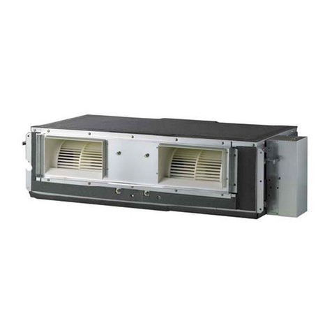
AUKS AFC-500CF/4 User manual

1
Technical Manual
FanCoil Unit
(Ceiling&Floor Type)

Service Manual
2
Contents
Part1General description...................................................................................................3
Part2.U n i t .............................................................................................................................5
Part3 Product selection.....................................................................................................31
Part4 Controller ................................................................................................................. 34
Part5 Trouble shooting......................................................................................................43

AUKS-Fan CoilGeneral description
3
P a r t 1General description
1Nomenclature

AUKS-Fan CoilGeneral description
4
2U n i t appearance
Series
Range ofthe A i r Volume(CFM)
Ceiling
&Floor
400CFM
500CFM
600CFM
800CFM
1000CFM

AUKS F a n CoilUnit information
5
P a r t 2.Unit
1.Feature...............................................................................................................................6
2.Specfication...................................................................................................................... 8
3.Capacity amendment......................................................................................................10
4.Demension...................................................................................................................... 14
5.Electrical wiringandconnection...................................................................................15
6.Installation .......................................................................................................................17
7.Explode v i e w ...................................................................................................................22

AUKS F a n CoilUnit information
6
1.Feature
Ceiling floor fan coil unit, as its name suggests, can either be suspended from the ceiling, or floor installed
against the wall.Compared with other fan coil units, it has the following advantages: Suspended from the
ceiling, it occupies no indoor space; Its installation synchronizes with decoration process, with connecting
pipeline buried in the ceiling, making the room more attractive and appealing; It can be alternatively floor
mounted against the wall, as a substitute of a floor standing air conditioner.
Application occasions:
Small super market,restaurant, office, meeting room, parlor o f villa,living room, e t c . Features:
◇ Suspended ceiling, installation under ceiling, saving room space, i t i s v e r y suitable forfamily o r office
place;
◇ Convenient a n d flexible forindoor u n i t installation, canb e installed under t h e ceiling o r o n t h e floor;
◇ WithSetting o r Auto t w o operation modes, multifanspeed, makes y o u feel morecomfortable;
◇ Shell w a s formed b y mold,and t h e appearance i s “slim”, “elegant”, “fashion” a n d “comfortable”;
◇ Special insulation design, achieves high heat insulation efficiency a n d n o condensation o n shell;
◇ Long t e r m a i r filter, t h e w a s h period i s t w o t i m e s longer t h a n normal filter, maintenance i s free;
◇ Adopting l o w noise centrifugal fan, strongw i n d b u t quiet operation, t h e silence design achieves
harmony residential living;
◇ All t h e installation a n d maintenance canb e done i n t h e bottom o f u n i t , saving t h e maintenance space;
◇ Auto-restart(optional);
◇ Standard remote controller a n d optional w i r e d controller;
◇ AUKSiliary e l e c t r i c heater forheat p u m p u n i t , w i t h fastheating a n d l o w ambient temperature
heating functions;
◇ Failure automatic detection, i f t h e r e i s afailure, t h e indicator will flasha n d t h e f a i l u r e codew i l l display
o n t h e w i r e d controller, t h e failure cause i s easier t o b e found..
◇ Ultraslim design, t h e thickness o n l y 2 0 5 mm, a n d h a v e v e r t i c a l and horizontal swingfunction.

AUKS F a n CoilUnit information
7
Function Introduction
T y p e
Item
AFC-**CF/4
400
500
600
800
1000
Comfort
Cooling
●
●
●
●
●
Heating
●
●
●
●
●
3-Speed
●
●
●
●
●
Adjustable ESP
-
-
-
-
-
Auto-restart(Optional)
●
●
●
●
●
Anti-cold w i n d
●
●
●
●
●
Afterheat w i n d blowing
●
●
●
●
●
Timing ON/OFF
●
●
●
●
●
Operation
T i m e display
●
●
●
●
●
Operation modedisplay
●
●
●
●
●
Fanspeed display
●
●
●
●
●
Timing ON/OFF display
●
●
●
●
●
Windangle display
●
●
●
●
●
Sleeping modedisplay
●
●
●
●
●
Health
Washable airfilter
●
●
●
●
●
Freshairinterface
●
●
●
●
●
Installation
Left/right drainage
-
-
-
-
-
Left/right pipeconnection
-
-
-
-
-
Down/back airsuction
-
-
-
-
-
Installation indicating board
-
-
-
-
-
Remarks:●Stands for“YES” -Stands for“NO”

AUKS F a n CoilUnit information
8
2.Specfication
Model
AFC-400CF/4
AFC-500CF/4
AFC-600CF/4
Air Volume
H i Speed
C F M
400
500
600
m 3
/h
680
850
1020
Medium Speed
C F M
300
375
450
m 3
/h
510
638
765
Low Speed
C F M
200
250
300
m 3
/h
340
425
510
Cooling Capacity
H i Speed
W
3600
4514
5406
Medium Speed
W
3075
3837
4595
Low Speed
W
2352
2934
3514
Heating Capacity
H i Speed
W
5418
6767
8115
Medium Speed
W
4605
5752
6898
Low Speed
W
3522
4399
5275
N o i s e Level
dB(A)
≤42
≤45
≤48
FanMotor
FanQuantity
2
2
3
Motor Quantity
1
1
1
Power Input
W
78
93
117
Water FlowVolume
kg/h
620
800
980
Hydraulic Resistance
kPa
16
20
22
Max.Working pressure
M P a
1.6
1.6
1.6
Dimension(W×D×H)
N e t
mm
929×660×205
929×660×205
1280×660×205
Packing
mm
1010×720×280
1010×720×280
1360×720×280
Net/Gross Weight
kg
24/27
25/28
30/35
Inlet/Outlet WaterPipe
R c 3 / 4 ″(DN20)
R c 3 / 4 ″(DN20)
R c 3 / 4 ″(DN20)
D r a i n Pipe
R 3 / 4 ″(DN20)
R 3 / 4 ″(DN20)
R 3 / 4 ″(DN20)
Stuffing Quantity(20/40/40H)
149/300/350
149/300/350
104/222/246
Note:
1 . Cooling capacity t e s t conditions:Air inlet temp.:27℃ DB/19.5℃ WB,Water inlet/outlet temp.:7℃ / 1 2 ℃ .
2 . Heating capacity t e s t conditions:Air inlet temp.:21℃ DB,Water inlet/outlet temp.:60℃.
3 . Noisel e v e l i s tested i n full-anechoic room.
4 . Parameters above mayb e modified a s product improvement. Wekeep t h e right t o change t h e
product specifications without prior n o t i c e .

AUKS F a n CoilUnit information
9
Model
AFC-800CF/4
AFC-1000CF/4
Air Volume
H i Speed
C F M
800
1000
m 3
/h
1360
1700
Medium Speed
C F M
600
750
m 3
/h
1020
1275
Low Speed
C F M
400
500
m 3
/h
680
850
Cooling Capacity
H i Speed
W
7210
9000
Medium Speed
W
6129
7665
Low Speed
W
4687
5862
Heating Capacity
H i Speed
W
10807
13512
Medium Speed
W
9186
11485
Low Speed
W
7025
8783
N o i s e Level
dB(A)
≤48
≤50
FanMotor
FanQuantity
3
4
Motor Quantity
1
1
Power Input
W
190
230
WaterFlowVolume
kg/h
1250
1580
Hydraulic Resistance
kPa
30
40
Max.Working pressure
M P a
1.6
1.6
Dimension(W×D×H)
N e t
mm
1280×660×205
1631×660×205
Packing
mm
1360×720×280
1710×720×280
Net/Gross Weight
kg
33/38
44/50
Inlet/Outlet Water Pipe
R c 3 / 4 ″(DN20)
R c 3 / 4 ″(DN20)
D r a i n Pipe
R 3 / 4 ″(DN20)
R 3 / 4 ″(DN20)
Stuffing Quantity(20/40/40H)
104/222/246
86/173/202
Note:
1 . Cooling capacity t e s t conditions:Air inlet temp.:27℃ DB/19.5℃ WB,Water inlet/outlet temp.:7℃ / 1 2 ℃ .
2 . Heating capacity t e s t conditions:Air inlet temp.:21℃ DB,Water inlet/outlet temp.:60℃.
3 . Noisel e v e l i s tested i n full-anechoic room.
4 . Parameters above mayb e modified a s product improvement. Wekeep t h e right t o change t h e
product specifications without prior n o t i c e .

AUKS F a n CoilUnit information
1 0
3Capacity amendment
3 . 1 T a b l e o f variable working condition performance forcooling capacity
Table o f variable w o r k i n g condition performance parameter under cooling mode
U n i t : W
Air inlet temperature℃
26℃DB/18. 7℃WB
27℃D B / 1 9 ℃WB
Waterinlet temperature ℃
5
7
9
5
7
9
Model
(CFM)
Water
flow
(kg/h)
Water
pressure
drop
(kPa)
T H
SH
T H
SH
T H
SH
T H
SH
T H
SH
T H
SH
400
430
8.1
2565
1944
2268
1823
1944
1593
2619
2052
2390
1931
2012
1688
550
11.5
2930
2187
2579
2025
2214
1769
3011
2309
2660
2133
2295
1877
650
15.5
3456
2349
3051
2160
2633
1877
3537
2457
3132
2268
2714
2012
750
20
3807
2417
3389
2214
2916
1917
3902
2538
3429
2336
3011
2039
500
600
18
3200
2425
2830
2274
2425
1987
3267
2560
2981
2409
2510
2105
700
24
3655
2729
3217
2527
2762
2207
3756
2880
3318
2661
2863
2341
800
30
4312
2931
3807
2695
3284
2341
4413
3065
3908
2830
3385
2510
900
37
4750
3015
4228
2762
3638
2392
4868
3167
4278
2914
3756
2543
600
750
21.5
3833
2905
3389
2724
2905
2381
3914
3066
3571
2885
3006
2522
850
26.8
4377
3268
3853
3026
3308
2642
4498
3449
3974
3187
3429
2804
950
32.7
5164
3510
4559
3228
3934
2804
5285
3672
4680
3389
4055
3006
1050
39
5688
3611
5063
3308
4357
2864
5830
3792
5124
3490
4498
3046
800
900
14.8
5661
4290
5005
4022
4290
3515
5780
4528
5273
4260
4439
3724
1100
21
6466
4827
5691
4469
4886
3903
6644
5095
5870
4708
5065
4142
1300
28
7627
5184
6733
4767
5810
4141
7806
5422
6912
5005
5988
4439
1500
36
8402
5333
7478
4886
6436
4231
8611
5601
7568
5154
6644
4499
1000
1200
23
7080
5366
6260
5031
5366
4397
7229
5664
6596
5329
5552
4658
1400
30
8086
6037
7117
5590
6111
4882
8310
6372
7341
5888
6335
5180
1600
38
9540
6484
8422
5962
7267
5180
9763
6782
8645
6260
7490
5552
1800
46.8
10509
6670
9353
6111
8049
5292
10770
7006
9465
6447
8310
5627

AUKS F a n CoilUnit information
1 1
variable w o r k i n g condition performance parameter t a b l e (continued)
Unit:W
Air inlet temperature ℃
27℃DB/19. 5℃WB
28℃D B / 2 2 ℃WB
Waterinlet temperature ℃
5
7
9
5
7
9
Model
(CFM)
Water
flow
(kg/h)
Water
pressure
drop
(kPa)
T H
SH
T H
SH
T H
SH
T H
SH
T H
SH
T H
SH
400
430
8.1
2714
2012
2403
1863
2213
1856
3402
2522
3078
2386
2781
2062
550
11.5
3119
2255
2768
2079
2410
1971
3902
2821
3551
2668
3200
2313
650
15.5
3699
2430
3267
2228
2849
2112
4577
3006
4199
2863
3780
2483
750
20
4037
2511
3618
2282
3161
2140
5063
3149
4617
2911
4131
2570
500
600
18
3385
2510
2998
2324
2761
2316
4244
3146
3840
2977
3470
2572
700
24
3891
2813
3453
2594
3007
2458
4868
3519
4430
3328
3992
2886
800
30
4615
3032
4076
2779
3555
2635
5710
3751
5238
3571
4716
3098
900
37
5036
3133
4514
2847
3944
2671
6316
3929
5760
3632
5154
3206
600
750
21.5
4055
3006
3591
2784
3307
2774
5084
3769
4600
3566
4156
3081
850
26.8
4659
3369
4135
3106
3600
2944
5829
4214
5305
3985
4780
3456
950
32.7
5528
3631
4882
3329
4258
3156
6839
4493
6274
4278
5649
3711
1050
39
6031
3752
5406
3409
4723
3198
7564
4706
6899
4350
6173
3840
800
900
14.8
5988
4439
5303
4111
4883
4096
7508
5565
6793
5266
6137
4549
1100
21
6883
4976
6108
4588
5318
4349
8611
6225
7836
5887
7061
5105
1300
28
8163
5363
7210
4916
6288
4661
10100
6635
9266
6318
8342
5480
1500
36
8909
5542
7985
5035
6976
4724
11173
6950
10190
6426
9117
5672
1000
1200
23
7490
5552
6633
5142
6108
5124
9391
6961
8496
6587
7676
5690
1400
30
8608
6223
7639
5739
6652
5439
10769
7785
9800
7362
8831
6385
1600
38
10210
6708
9018
6149
7865
5830
12633
8299
11589
7902
10434
6854
1800
46.8
11142
6931
9987
6298
8726
5908
13974
8693
12745
8037
11403
7094

AUKS F a n CoilUnit information
1 2
3 . 2 T a b l e o f variable working condition performance forheating capacity
Table o f variable w o r k i n g condition performance parameter under heating mode
Unit:W
Air inlet temperature ℃
18℃D B
20℃D B
Water inlet temperature ℃
40
45
50
60
70
80
40
45
50
60
70
80
Model
(CFM)
Water
flow
(kg/h)
Water
pressure
drop
(kPa)
400
430
8.1
2517
3086
3669
4806
5944
7096
2289
2872
3427
4579
5731
6868
550
11.5
2702
3314
3939
5163
6400
7623
2460
3072
3683
4921
6144
7381
650
15.5
2915
3584
4238
5560
6897
8205
2659
3313
3982
5318
6627
7963
750
20
3057
3768
4451
5830
7224
8618
2787
3470
4181
5560
6954
8347
500
600
18
3144
3854
4582
6003
7424
8863
2860
3588
4280
5719
7158
8579
700
24
3374
4138
4920
6447
7992
9520
3073
3836
4600
6145
7672
9218
800
30
3641
4476
5293
6944
8614
10248
3321
4138
4973
6642
8276
9946
900
37
3819
4707
5559
7282
9023
10763
3481
4334
5222
6945
8685
10426
600
750
21.5
3770
4622
5495
7199
8903
10628
3429
4302
5133
6858
8584
10288
850
26.8
4047
4963
5900
7731
9584
11416
3685
4601
5516
7369
9201
11054
950
32.7
4367
5368
6347
8328
10331
12290
3983
4963
5964
7966
9926
11928
1050
39
4579
5644
6667
8733
10820
12907
4175
5197
6262
8328
10415
12503
800
900
14.8
5269
6460
7681
10062
12444
14856
4793
6014
7175
9586
11998
14379
1100
21
5657
6937
8247
10807
13397
15958
5151
6431
7711
10301
12862
15452
1300
28
6103
7502
8872
11641
14439
17178
5567
6937
8336
11134
13873
16672
1500
36
6401
7889
9319
12206
15124
18042
5835
7264
8753
11641
14558
17476
1000
1200
23
6588
8077
9604
12581
15559
18574
5993
7519
8971
11986
15001
17979
1400
30
7072
8673
10310
13512
16750
19951
6439
8040
9640
12879
16080
19318
1600
38
7631
9380
11092
14554
18053
21478
6961
8673
10422
13921
17346
20845
1800
46.8
8003
9864
11651
15261
18909
22557
7296
9082
10944
14554
18202
21850

AUKS F a n CoilUnit information
1 3
Table o f cvariable w o r k i n g condition performance parameter under heating mode (continued)
Unit:W
Air inlet temperature ℃
21℃D B
22℃D B
Waterinlet temperature ℃
40
45
50
60
70
80
40
45
50
60
70
80
Model
Water
flow
(kg/h)
Water
pressure
drop
(kPa)
400
430
8.1
2190
2744
3313
4465
5617
6740
2062
2616
3199
4351
5489
6626
550
11.5
2332
2958
3570
4807
6030
7267
2204
2830
3442
4665
5902
7125
650
15.5
2517
3185
3840
5162
6499
7807
2389
3043
3712
5034
6357
7693
750
20
2659
3342
4039
5418
6812
8205
2503
3200
3882
5276
6669
8077
500
600
18
2735
3428
4138
5577
7016
8419
2575
3268
3996
5435
6856
8277
700
24
2913
3694
4458
6003
7530
9076
2753
3534
4298
5825
7371
8898
800
30
3144
3978
4795
6447
8116
9750
2984
3801
4635
6287
7939
9608
900
37
3321
4174
5044
6767
8508
10248
3126
3996
4849
6589
8330
10088
600
750
21.5
3280
4111
4963
6688
8413
10096
3088
3919
4792
6518
8222
9926
850
26.8
3493
4430
5346
7199
9031
10884
3301
4238
5154
6986
8839
10671
950
32.7
3770
4771
5751
7732
9734
11694
3578
4558
5559
7540
9521
11523
1050
39
3983
5005
6049
8115
10202
12290
3749
4792
5815
7902
9989
12098
800
900
14.8
4585
5746
6937
9348
11759
14111
4317
5478
6698
9110
11491
13873
1100
21
4883
6193
7473
10063
12623
15214
4615
5925
7205
9765
12355
14916
1300
28
5270
6669
8038
10807
13606
16344
5002
6371
7770
10539
13308
16106
1500
36
5567
6996
8455
11343
14261
17178
5240
6699
8128
11045
13963
16910
1000
1200
23
5732
7184
8673
11688
14703
17644
5397
6849
8375
11390
14368
17346
1400
30
6104
7742
9343
12581
15782
19020
5769
7407
9008
12209
15447
18648
1600
38
6588
8338
10050
13512
17011
20436
6253
7966
9715
13177
16639
20138
1800
46.8
6961
8747
10571
14182
17830
21478
6551
8375
10162
13810
17458
21143

AUKS F a n CoilUnit information
1 4
4 . Demension
AFC-400CF/4, AFC-500CF/4
AFC-600CF/4, AFC-800CF/4
AFC-1000CF/4

AUKS F a n CoilUnit information
1 5
5 . Electrical wiring a n d connection

AUKS F a n CoilUnit information
1 6
Introduction o f control board QFPD-3F-HCE2 (PCB) sockets
Neutra
linsert
Primary of
transformer
Electric
heater
Line for
electric
heater
Line
insert
Heat
water
valve
Cold
water
valve
Water
pump
Indoor f a n output
High
M i d
L o w
Neutral
4-DIPswitch
W a t e r level
switch
Air return
temperature
Wiredcontrol
receiver
3-DIP
switch
Step motor
output
Display
board
Secondary of
transformer

AUKS F a n CoilUnit information
1 7
6 . Installation
6 . 1 Preparation andequipments before installation
◇ W o r k preparation
Required materials a n d major devices:
a . Thefancoilt o b e u s e d shallhave t h e conformity certificated issued b y t h e factory, o r quality appraisal
documents.
b . Thestructural a n d installation type, outlet direction, w a t e r inlet position o f t h e fancoilu n i t shallmeett h e
requirement o f design and installation.
c.Themajor materials a n d accessories forinstallation shallh a v e specifications a n d types t h a t meett h e
design requirements a n d b e provided w i t h conformity certificates b y t h e factories.
d . Electrical hammers, manual and power drills, adjustable wrenches, socket wrenches, steelsaws,t u b e
p l i e r s , hand hammers, bench vices, thread t a p s , thread reamers, horizontal ruler, plum b o b , hand
pumps, pressure t a b l e a n d g a s welding t o o l s .
◇ Working condition
a . Thefancoila n d i t s major p a r t s and accessories a r e arrived a t t h e w o r k site,t o o l s needed for
installation a r e provided and site,water a n d power source forinspection before installation a r e
available.
b . Structural construction i s complete, including waterproof layer w o r k s o n t h e roof, indoor w a l l s a n d f l o o r
finish i s complete.
c.Theposition a n d dimension o f t h e installation meett h e requirements o f design, d r y p i p e installation o f
t h e a i r conditioning systemi s complete a n d t h e elevation o f t h e reserved p o r t o f t h e branch pipe
connecting t o fancoilmeett h e requirement.
◇Operation process
a . Theprocess:Preliminary inspection →Workpreparation →Testrunning o f t h e motor→Heat
exchanger w a t e r pressure t e s t →Manufacturer a n d installation o f t h e suspension bracket →Installation
o f fancoil→Pipe connection →Inspection
b . Before installing t h e fancoil, t h e case and surface heat exchanger o f e a c h motorshall b e checked for
damage, rusting a n d other defects.
c.Each f a n coilshallundergo power-on testing, during w h i c h t h e r e shall b e n o attrition between t h e
mechanical p a r t s and n o leakage i n t h e electrical p a r t s .
d . Each f a n coilshallundergo water pressure testing ,w i t h t h e t e s t i n g intensity equaling 1 . 5 t i m e s t h e
w o r k pressure. Observe for2 - 3 m i n after t h e pressure i s set,t h e r e shallb e n o leakage.
e . Thefancoilshall b e suspended horizontally w i t h t h e suspension bracket installed even and secured, a t
correct position. Thesuspension rod shall n o t b e allowed t o swayf r e e l y . Theconnection between t h e
rod and t h e t r a y shallb e secured evenly w i t h t w o n u t s .
f.Theconnection between cold/heat medium w a t e r pipe a n d t h e fancoilshallb e structured w i t h steelo r
copper pipe ,w i t h connecting p i p e being straight. Thetightening shallb e applied a t t h e h e x connector
w i t h aw r e n c h t o prevent t h e copper p i p e frombeing damaged. I t i s suggested t h a t t h e condensed
w a t e r pipe b e structured w i t h softmaterial. When t h e length o f t h e h o s e i s n o t greater t h a n 300mm, a
transparent rubber pipe shallb e used, w i t h aclampt o a v o i d leakage a n d correct slopesot h a t t h e
condensed w a t e r cansmoothly f l o w t o designated position a n d t h e r e will b e n o still water o n t h e water
plate.
g . Theconnection between t h e f a n coila n d t h e cold/heat medium pipe shallb e madeafter t h e system
cleaning a n d pollution discharge t o avoid heat exchanger jams.
h . Access doors shallb e provided fort h e buried installed horizontal fancoiland t h e falseceiling ,fort h e
convenience o f t h e removal a n d service o f t h e u n i t .
◇ Quality standard
Items t o b e ensured:
a . Thefancoilb e installed stably a n d securely.
Inspection method: Measure w i t h ahorizontal ruler a n d aplumb.
b . Noleakage a t t h e connection between t h e f a n coila n d i t s inlet a n d outlet water pipes i s permitted. The
pipe o f condensed water shall h a v e aslopemeeting t h e training requirement and tight connection t o t h e
vent a n d a i r return chamber.
Inspection method: Measuring w i t h aruler, observation a n d checking t h e testing records.
c.Basic i t e m s : Thevent o f t h e fancoilshallb e tightly connected w i t h n o a i r leakage.
Inspection method: Observation.

AUKS F a n CoilUnit information
1 8
Protection o f finished products:
a . After t h e fancoilsa r e shipped t o t h e site,measures shall b e t a k e n t o keep t h e m i n good condition a n d
t o place t h e m i n a n orderly manner. Thef a n coilsshallb e protected fromrainy a n d snowy weathers.
b . When w o r k i n g i n winter, completely d r a i n w a t e r fromt h e fancoilafter water pressure testing, t o prevent
i t frombeing frozen.
c.Thefancoilshallb e installed immediately after i t i s delivered t o t h e sitea n d careshould b e t a k e n
during t h e cross w o r k i n g w i t h other process, t o protect t h e finished products frombeing bumped.
Qualityissues t h a t require attention:
Preventive measures f o r issues occur frequently
a . Since t h e surface heat exchanger canb e easily damaged b y t h e coldtemperature during winter
weathers, i t i s required t o discharge a l l w a t e r after t h e w a t e r pressure testing, t o avoid such damage.
b . Since fancoilscanb e easily damaged d u e t o bumps during movement, t h e y shall b e placed i n asingle
row a n d gently handled
c.Since fancoilheat exchangers canb e easily jammed, n o fancoil(after connected t o i t s p i p e )shall b e
p u t t o operation before cleaning a n d pollution discharge, t o prevent i t frombeing jammed.
d . Since t h e condensed w a t e r p l a t e o f afancoilcanb e easily jammed, t h e foreign matters i n t h e p l a t e
shallb e removed before t h e fancoilcanb e operated, t o ensure smooth flowo f t h e condensed water.
Qualityrecords:
a . Qualityinspection review t a b l e fora i r treatment chamber building and installation subw o r k .
b . Self-inspection a n d mutual inspection records.
c.Workinspection formforpreliminary inspection w o r k s
d . Inspection record t a b l e forincoming equipments.
Installation precaution
◇ Considerations o f noise a n d vibration
a . Canvass jointsshallb e installed between t h e machine and t h e a i r return/feed pipes t o prevent
secondary n o i s e a n d vibration fromtraveling fromt h e fancoilt o a i r pipes a n d t h e n t o t h e building.
b . Air flowrate shallb e considered when selecting t h e sizeo f a i r return/feed pipes t o minimize t h e n o i s e
level.
Notes:L o w speed a i r pipes a r e usually u s e d fora i r conditioners. The“constant pressure” method i s most
commonly u s e d t o determine t h e size,whereby t h e attrition l o s s o f t h e straight section o f ap i p e i s defined
a s 0.1mmAq/m, a n d t h e sizecanb e determined u s i n g a n “air p i p e ruler”. Thewidth/height ratio o f a
rectangular a i r d u c t shall b e w i t h t h e range o f 1 ≤ W / H ≤ 4 .
Thea i r speed o f agrille t y p e feed v e n t usually i s 3 m / s .
Thea i r speed o f agrille t y p e return vent usually i s 2.5m/s.
Thea i r speed o f afresha i r louver usually i s 2.0m/s.
◇ Cautions
a . Theu n i t shallb e installed b y professionals w h o familiar w i t h t h i s t y p e o f products a n d know t h e
applicable l o c a l rules;
b . During t h e installation, t h e unit shallnever b e moved b y grasping t h e fanblade a n d volute b y hands;
c.Theu n i t shallb e securely suspended fromaw e l l fixedpoint w i t h enough strength t o bear t h e weight o f
t h e u n i t a n d i t s vibration during operation; Theu n i t shall b e kepthorizontal, o r t h e condensed w a t e r
mayoverflow;
d . I f t h e a i r d u c t p o r t does n o t matcht h e port o f t h e a i r f e e d vent, connect t h e t w o w i t h aa i r duct
connection o f variable section prepared in-situ.
e . I t i s suggested t h a t aflexible connecting p i p e and t a p e sealing a r e used when connecting water outlet
pipe ,w i t h atorque not higher t h a n 205.6N.m(21Kgf.m)t o a v o i d water leakage d u e t o cracking.
f.Heatpreservation a n d e x t r a valves shall b e provided fort h e inlet a n d outlet water pipes;

AUKS F a n CoilUnit information
1 9
g . Afilter shallb e installed a t t h e inlet opening o f t h e coldw a t e r p u m p t o prevent t h e heat exchanger from
being polluted a n d blocked;
h . As forfancoils without aa i r filter, i n s t a l l afilter screen o v e r t h e a i r return opening ,t o prevent d u s t from
jamming t h e finso f t h e fancoila n d t o ensure t h e heat exchanging effect;
i . Before wiring, check i f t h e voltage, frequent a n d phases o f t h e power supply a r e a s required b y t h e unit.
Apower voltage deviation n o t greater t h a n 10% o f t h e rated value i s preferred.
j.Aswitch control shared b y several u n i t s o f different models i s strictly banned.
k.Thetemperature o f t h e u n i t shallb e n o lower t h a n 5 ℃ (t o a v o i d condensation) when coldw a t e r i s used,
a n d n o higher t h a n 8 5 ℃(usually60℃)when h o t water i s u s e d a n d t h e w a t e r shall b e clean.
6 . 2 U n i t installation
The distance between indoor unit a n d obstacle
Unitsuspension
◇ Select the suspension foundation
Thesuspension foundation i s astructure o f either wooden frameo r
reinforced concrete. It mustb e firmand reliable to bear a t l e a s t 4t i m e s
weight o f itself and capable o f bearing vibration forl o n g periods;
◇ Fixing o f suspension foundation
Fixthe suspension bolts either a s shown i n the picture o r b y asteel o r
wooden bracket;
◇ Adjust the relative positions o f the suspension hooks to ensure the indoor
unit i s level i n a l l directions. Useaspirit level to ensure this, otherwise
waterleakage, a i r leakage e t c . willb e resulted;
◇ Tighten the nuts and ensure that the hooks a r e tightly connected to the nuts and sMDms,a n d t h e r e i s n o
phenomenon o f v i r t u a l hanging;
◇ A f t e r the unit i s installed ensure i t i s secure and does not shake o r sway.
Drainagep i p e installation
◇ Thedrain p i p e should b e properly insulated to prevent the generation o f condensation,seep i c t u r e a s
follows:
Heatinsulation material: rubber insulation pipe w i t h t h e thickness o f moret h a n 8 m m
◇ Drainage pipe musth a v e adownward gradient (1 /5 0 1 / 100).If t h e d r a i n p i p e i s installed u p s a n d
downs, i t w i l l cause w a t e r backflow o r leakage e t c .
Thepipe should not risea t any point.

AUKS F a n CoilUnit information
2 0
◇When finish installation,please carry out the drainage test to ensure that the water flow through the
pipeline fluently, and carefully observe the junction to ensure that there is no water leakage at the
junction. If the unit is installed in the newly built house, strongly recommend that this test taken before
the ceiling installation. Even it is the heating only unit, this test is unavoidable.
6.3Electrical connection precaution
Warning
Installation of electric items must be carried out by qualified, professional technicians. An isolated circuitry
should be fixed with whole-pole disconnection devices, which is with at least 3mm gap of touch point. .
Power supply and indoor to outdoor connection should use special cable. Providing the necessity of
installation or replacement, the professional technician of service store appointed by manufacturer must
be required, while self-operation by users is prohibited.
Incaseofany electric shock accident, thecreepage protection devices /power supply on-off and breaker
mustberequired w i t h power supply.
Machine mustbeearthed surely.Ifnot, it’ll beprobably caused creepage.
T h e power cordshallconsist w i r e s of227IEC53(RVV) typespecified inGB5023 orthose ofequivalent
grades orabove .Secure thew i r e s w i t h fixtures, sothat theterminals will not easily dislodge under
external forces. Incorrect connection orfixing maycause afireorother hazards. T h e internal and external
connecting cableshallconsist w i r e s of245IEC57(YZW) typespecified inGB5013 orthose ofequivalent
grades orabove.
N o t i c e
T h e earth line isneither allowed toconnect togas pipe, water pipeorcircuitry oftelephone orlighting rod,
nor totheearth line ofother devices.
Others
●Please connect thepower cordaccording totheinstructions ofthecircuit diagram.
●Securely and firmly connect thew i r e s totheterminal holder w i t h cablefixtures, toprevent theexternal
forcesfromacting onthew i r e s and causing dangers.
6 . 4 Pressure testing andtest runwithwater.
Preparation before test run
◇ Before initial operation, please remove foreign matters i n t h e w a t e r t r a y , plastics and around t h e fancoil
a n d check i f t h e installation points o f t h e w a t e r pipes a n d t h e cables a r e correct.
◇ Before initial operation, t h e w a t e r inlet a n d outlet valves o f t h e u n i t shallb e closed firstand t h e pipe
systemo f t h e cooling w a t e r b e cleaned before opening t h e valves.
◇ Duringt h e initial operation, t h e ventilation v a l v e o n t h e water return pipe shallb e opened t o exhaust t h e
a i r fromt h e fancoila n d t h e pipeline.
Pressure testing a n d test runwithwater
Before carrying out system pressure testing for an AC system equipped with a buriedly and horizontally
installed fan coil, a pressure testing plan shall be prepared and a proper pressure test pump be selected.
The test conditions shall be carefully noted during the testing and the pressure change of he system shall
be monitored from time to time.
Be careful about t h e following when preparing t h e pressure t e s t plan:
a . Theventilation v a l v e o n t h e w a t e r collecting head shall b e opened before adding water t o t h e fancoil.
W a i t e u n t i l t h e a i r i n t h e fancoili s emptied before closing t h e valve.
b . Pressure t e s t shall b e carried out a t atemperature o f 5 ℃o r above, otherwise t h e r e shallb e
anti-freezing measure i n place.
c.During t h e w a t e r pressure t e s t , t h e pressure shallb e increased i n astaged, slowa n d uniform manner.
W a i t u n t i l t h e water p u m p i s stopped a n d w a t e r pressured stablebefore carefully check i f t h e r e i d w a t e r
This manual suits for next models
4
Table of contents
Other AUKS Air Conditioner manuals
Popular Air Conditioner manuals by other brands
Carrier
Carrier 48TFD008-014 Installation and service instructions
Coleman
Coleman ECHELON AC21 Series Technical guide
Vertiv
Vertiv Liebert AHU user manual
KITANO
KITANO Roka II Series Operation and installation manual
Carrier
Carrier 42QHC007D8S Series installation manual
Heat Controller
Heat Controller B-MMC09FA-1 Service manual


