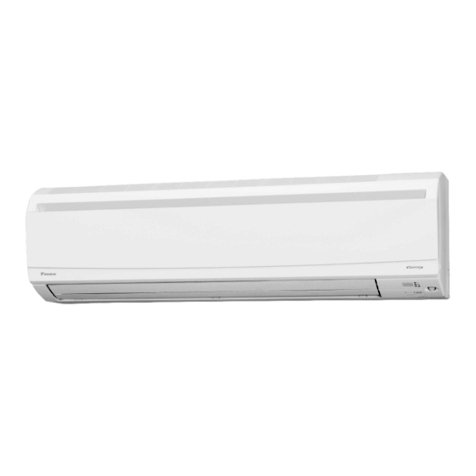
AUKS ALCA-H24/4DR1 User manual

AUKS DC Inverter 1Drive1 50HZ R410A
1
Service manual
(DC Inverter 1 Drive 1 50Hz R410a)

AUKS DCInverter 1Drive15 0 H Z R410A General description
2
Contents
Part1General description...................................................................................................3
Part2 Indoor unit ..................................................................................................................6
Part3Universal outdoor unit ............................................................................................78
Part4 Trouble shooting ....................................................................................................1 1 0
Part5 Controller................................................................................................................138
Part6Sensor resistance t a b l e ........................................................................................ 154

AUKS DCInverter 1Drive15 0 H Z R410A General description
3
P a r t 1General description
1 . Nomenclature

AUKS DCInverter 1Drive15 0 H Z R410A General description
4
2 . U n i t appearance
Series
P i c t u r e oftheindoor unit
Four-way
Cassette
18k Btu/h
24k Btu/h
36k Btu/h
48k Btu/h
Ceiling
&Floor
18k Btu/h
24k Btu/h
36k Btu/h
48k Btu/h
60k Btu/h
MidE S P
Duct
18k Btu/h
24k Btu/h
36k Btu/h
48k Btu/h
60k Btu/h
Capacity
(BTU)
18000
24000
36000
48000
60000
Outdoor U n i t
18/4
24/4
36/4
48/5
60/5

AUKS DCInverter 1Drive15 0 H Z R410A General description
5

AUKS DCInverter 1Drive150HZ R410A Indoor unit
6
P a r t 2Indoor unit
Four-way cassette ................................................................................................................8
Ceiling & floor t y p e .............................................................................................................34
Ducted T y p e Indoor U n i t .................................................................................................... 5 6

AUKS DCInverter 1Drive15 0 H Z R410A General description
7

AUKS DCInverter 1Drive15 0 H Z R410A Four-way cassette
8
Four-way cassette
1.Feature.......................................................................................................................9
2.Specification ........................................................................................................... 1 1
3.Capacity Amendment ............................................................................................ 15
4.Dimension .............................................................................................................. 18
5.Electrical wiring andconnection ......................................................................... 19
6.Installation...............................................................................................................22
7.Explode v i e w .......................................................................................................... 28

AUKS DCInverter 1Drive15 0 H Z R410A Four-way cassette
9
1 . Feature
DC Inverter type Four-way cassette unit (heat pump), is installed under the ceiling, compared with Floor
&Standing type A/C, it has following advantages: saving room space; Ceiling installation combining with
the decoration, makes the room more elegant; Flexible installation in anywhere in the ceiling and
4-direction blowing, makes the indoor temperature is even and makes you feel more comfortable, so
Cassette type A/C is a perfect replacing Product of Floor &Standing type A/C.
Application occasions:
Small super market,restaurant, office, meeting room, villa meeting room, family bedroom a n d soo n ,
a n d i t cane v e n b e used a s t h e updating Product formodern residential A/C.
Features:
◇Concealed design, ceiling installation, room space saving, i t i s v e r y suitable forfamily o r office
occasion;
◇WithSetting o r Auto t w o operation modes, four-way blowing, strongcirculating w i n d , multiw i n d speed,
t h e cooling o r heating capacity canreach t o e a c h corner o f t h e room;
◇ One-step formed shellb y mold,appearance i s elegant;
◇ Special insulation design, achieves high heat insulation efficiency, a n d n o condensation o n shell;
◇Built-in d r a i n pump, drain-head height i s u p t o 1.2meters, creating t h e ideal solution forperfect water
drainage, a l s o construction a n d installation i s mucheasier a n d convenient;
◇ Long t e r m a i r filter, w a s h period i s t w o t i m e s longer t h a n normal filter, a n d maintenance i s free;
◇3 D h e l i x a i r blade ensures t h e a i r f l o w sufficiently, reduces t h e unit thickness, a n d reduces t h e operation
n o i s e greatly;
◇ Integrated electric control b o x , t h e E-box i s safely covered b y metalplate, forbetter fire-resistance;
I t i s easy t o repair t h e control p a r t .
◇Plastic d r i p t r a y adopts innovative foam-PS combined w i t h plastic technical, t h e thickness o f plastic
reaches 1 m m , a v o i d a n y leakage;
◇ Ingenious hook design, t h e panel i s convenient t o install o r remove;
◇ F r e s h a i r intake design, leading i n fresha i r t o improve indoor a i r quality anytime;
◇ Auto-restart function;
◇ Standard remote controller a n d optional w i r e d controller;
◇Failure automatic detection, i f t h e r e i s afailure, t h e indicator w i l l flasha n d t h e failure codewill display
o n t h e w i r e d controller, t h e failure cause i s easier t o b e found.

AUKS DCInverter 1Drive15 0 H Z R410A Four-way cassette
1 0
Function introduction
Function
N a m e
ALCA-H*4*DR1
ALCA-H*5*DR1
18/4
24/4
36/4
48/5
60/5
Protection
Function
highpressure protection
-
-
-
○
○
lowpressure protection
-
-
-
○
○
over-current protection ofcompressor
○
○
○
○
○
over-high temperature ofcondenser middle
○
○
○
○
○
over-high discharge temperature ofcompressor
○
○
○
○
○
Phase protection
-
-
-
-
-
Heating over-heat protection
○
○
○
○
○
Anti-freeze protection
○
○
○
○
○
Sensor failure alarm
○
○
○
○
○
Error codedisplay function
○
○
○
○
○
Comfortable
Function
Cooling
○
○
○
○
○
Heating
○
○
○
○
○
3fanspeed
○
○
○
○
○
static pressure adjustable
-
-
-
-
-
Auto-restart (optional)
○
○
○
○
○
Anti-cold w i n d
○
○
○
○
○
Blow exhaust heat
○
○
○
○
○
T i m e r
○
○
○
○
○
Opretating
display
clock display
○
○
○
○
○
operating modedisplay
○
○
○
○
○
fanspeed display
○
○
○
○
○
defrosting display
○
○
○
○
○
timing on/off display
○
○
○
○
○
w i n d guiding angle display
-
-
-
-
-
sleeping display
○
○
○
○
○
Operation
mode
Auto operation
○
○
○
○
○
Dehumidify operation
○
○
○
○
○
Auto defrosting
○
○
○
○
○
Ventilation function
○
○
○
○
○
Low temperature cooling function
-
-
-
-
-
Health
function
Removable airfilter
○
○
○
○
○
freshairfunction preserved
○
○
○
○
○
Installation
adaptability
Optional leftand right water drain
-
-
-
-
-
Optional leftand right connection AUKSiliary pipe
-
-
-
-
-
Optional rear and downward airreturn
-
-
-
-
-
Installation instruction plate isavailable
○
○
○
○
○
Remarks: ○Stands for “YES” -Stands for “NO”

AUKS DCInverter 1Drive15 0 H Z R410A Four-way cassette
1 1
2 . Specification
Model
Indoor
ALCA-H18/4DR1
ALCA-H24/4DR1
ALCA-H36/4DR1
Panel
M B 1 3
M B 1 2
M B 1 2
Outdoor
AL-H18/4DR1(U)
AL-H24/4DR1(U)
AL-H36/4DR1(U)
Power Supply
V~,Hz,
Ph
220~240,50,1
220~240,50,1
220~240,50,1
Capacity
Cooling
Btu/h
20000-18000-5500
26500-24000-7200
40000-36000-10800
W
5610-5100-1530
7920-7200-2160
11000-10000-3000
Heating
Btu/h
20140-19000-4750
29700-27000-6750
43125-37500-11250
W
5936-5600-1400
8690-7900-1975
13225-11500-3450
Electric
D a t a
Rated Cooling Power Input
W
2053-1579-474
2880-2215-665
4012-3086-926
Rated Heating Power Input
W
2011-1547-464
2813-2164-649
4118-3168-950
Rated Cooling Current
A
9.81-7.55-2.25
13.78-10.60-3.21
19.19-14.77-4.45
Rated Heating Current
A
9.62-7.40-2.20
13.44-10.36-3.11
19.71-15.16-4.55
Performan
ce
EER
W/W
3.23
3.25
3.24
C O P
W/W
3.62
3.65
3.63
Indoor Fan
Motor
Model
YDK30-6E1
XD30A
YDK45-6 Q
Brand
Sinjun
Sinjun
Sinjun
Output Power xFan
quantity
W
30×1
30×1
45×1
Capacitor
uF
2.5
3
4
Speed (Hi/Mi/Lo)
r/min
920/850/750
500/430/320
650/520/450
Indoor C o i l
a.Number O f R o w
2
2
2
b.Tube Pitch(a)x R o w
Pitch(b)
mm
20.5×12.7
20.5×12.7
20.5×12.7
c.FinPitch
mm
1.5
1.6
1.4
d.FinMaterial
Hydrophilic
aluminum fin
Hydrophilic
aluminum fin
Hydrophilic
aluminum fin
e.Tube O u t s i d e Dia.and
Material
mm
φ 7 ,Inner grooved
φ 7 ,Inner grooved
φ 7 ,Inner grooved
f.Coil Length xHeight x
Width
mm
1160×184.5×25.4
2014×205×25.4
2014×205×25.4
g.Heat Exchanging Area
m
2
5.76
9.43
12.00
Indoor
U n i t
Indoor Air Flow(Hi/Mi/Lo)
m
3
/h
850/680/595
1100/880/770
1500/1200/1050
N o i s e Level(Hi/Mi/Lo)
dB(A)
41/38/32
45/42/36
48/45/39
N e t Dimension (W*H*D)
mm
615×615×263
835×835×250
835×835×250
Packing Dimension
(W*H*D)
mm
700×690×330
900×900×330
900×900×330
N e t Weight
Kg
18
24
24
G r o s s Weight
Kg
22
27.5
27.5
Panel
N e t Dimension (W*H*D)
mm
650×650×55
950×950×55
950×950×55

AUKS DCInverter 1Drive15 0 H Z R410A Four-way cassette
1 2
Packing Dimension
(W*H*D)
mm
710×710×80
1000×1000×100
1000×1000×100
N e t weight
Kg
3
5
5
G r o s s weight
Kg
5
7
7
Refrigeran
tPipe
Liquid Side
mm
6.35(1/4)
9.52(3/8)
9.52(3/8)
G a s Side
mm
12.7(1/2)
15.88(5/8)
15.88(5/8)
Drainage
mm
R3/4in(DN20)
R3/4in(DN20)
R3/4in(DN20)
M a x . Refrigerant Pipe
Length
m
20
30
30
M a x . Difference InLevel
m
15
15
20
Operation Temperature Range
℃
16~32
16~32
16~32
Ambient Temperature
Range(Cooling/Heating)
℃
16~49/-15~24
16~49/-15~24
16~49/-15~24
Connectio
nWiring
Power Wiring(Indoor)
mm
2
3×1mm
2
3×1mm
2
3×1mm
2
Power Wiring(Outdoor)
mm
2
3×2.5mm2
3×2.5mm2
3×2.5mm2
Signal Wiring
mm
2
2×1mm
2
2×1mm
2
2×1mm
2
WirelessRemote Controller
YKR-L/300E
YKR-L/300E
YKR-L/300E
Application Area
m
2
21-35
28-47
42-70
Qty’per 20’&40’&40HQ(Only For
Reference)
Set
57/120/144
39/76/96
30/70/76
Note:
1 . Workingcondition o f t h e cooling capacity measured: Inside t h e room DB temperature 2 7 ℃, W B
temperature19℃;Outside o f t h e room DBtemperature 3 5 ℃, W B temperature 2 4 ℃; W o r k i n g condition
o f t h e heating capacity measured:Inside t h e room DB temperature 2 0 ℃, O u t s i d e o f t h e room DB
temperature 7℃ , W B temperature 6 ℃.
2 . Parameters above a r e a l l measured when t h e connecting pipe i s 5meters.
3 . Parameters above mayb e modified a s product improvement. W e keept h e right t o change t h e product
specifications without prior n o t i c e , please t a k e t h e parameters listed o n t h e nameplate a s criterion.

AUKS DCInverter 1Drive15 0 H Z R410A Four-way cassette
1 3
Model
Indoor
ALCA-H48/5DR1
ALCA-H60/5DR1
Panel
M B 1 2
M B 1 2
Outdoor
AL-H48/5DR1(U)
AL-H60/5DR1(U)
Power Supply
V~,Hz,
Ph
380~415,50,3
380~415,50,3
Capacity
Cooling
Btu/h
51800-48000-1440
0
63000-60000-1800
0
W
15120-14000-4200
16800-16000-4800
Heating
Btu/h
56100-51000-1785
0
69300-63000-2205
0
W
17050-15500-5425
19800-18000-6300
Electric D a t a
Rated Cooling Power Input
W
5582-4294-1288
6479-4984-1495
Rated Heating Power Input
W
5461-4201-1260
6429-4945-1484
Rated Cooling Current
A
9.84-7.57-2.27
11.18-8.60-2.57
Rated Heating Current
A
9.68-7.45-2.23
10.95-8.42-2.54
Performance
EER
W/W
3.26
3.21
C O P
W/W
3.69
3.64
Indoor FanMotor
Model
XD80A
XD80A
Brand
Sinjun
Sinjun
Output Power xFanquantity
W
80×1
80×1
Capacitor
uF
6
6
Speed (Hi/Mi/Lo)
r/min
695/585/495
695/585/495
Indoor C o i l
a.Number O f R o w
2
2
b.Tube Pitch(a)x R o w Pitch(b)
mm
20.5×12.7
20.5×12.7
c.FinPitch
mm
1.4
1.4
d.FinMaterial
Hydrophilic
aluminum fin
Hydrophilic
aluminum fin
e.Tube O u t s i d e Dia.and Material
mm
φ7
,Inner grooved
φ7
,Inner grooved
f.Coil Length xHeight xWidth
mm
2014×246×25.4
2014×246×25.4
g.Heat Exchanging Area
m
2
14.66
14.66
Indoor U n i t
Indoor Air Flow(Hi/Mi/Lo)
m
3
/h
1800/1440/1260
1800/1440/1260
N o i s e Level(Hi/Mi/Lo)
dB(A)
50/47/41
50/47/41
N e t Dimension (W*H*D)
mm
835×835×290
835×835×290
Packing Dimension (W*H*D)
mm
900×900×370
900×900×370
N e t Weight
Kg
26.5
26.5
G r o s s Weight
Kg
30.5
30.5
Panel
N e t Dimension (W*H*D)
mm
950×950×55
950×950×55
Packing Dimension (W*H*D)
mm
1000×1000×100
1000×1000×100
N e t weight
Kg
5
5
G r o s s weight
Kg
7
7
Refrigerant Pipe
Liquid Side
mm
9.52(3/8)
9.52(3/8)
G a s Side
mm
19.05(3/4)
19.05(3/4)

AUKS DCInverter 1Drive15 0 H Z R410A Four-way cassette
1 4
Drainage
mm
R3/4in(DN20)
R3/4in(DN20)
M a x . Refrigerant Pipe Length
m
50
50
M a x . Difference InLevel
m
30
30
Operation Temperature Range
℃
16~32
16~32
Ambient Temperature Range(Cooling/Heating)
℃
16~49/-15~24
16~49/-15~24
Connection Wiring
Power Wiring( Indoor)
mm
2
3×1mm
3
3 × 1 m m 3
Power Wiring( Outdoor)
mm
2
5×1.5mm3
5×1.5mm3
Signal Wiring
mm
2
2×1mm
2
2 × 1 m m 2
WirelessRemote Controller
YKR-L/300E
YKR-L/300E
Application Area
m
2
56-93
64-107
Qty’per 20’&40’&40HQ(Only ForReference)
Set
26/54/54
26/54/54
Note:
1 . Working condition o f t h e cooling capacity measured: I n s i d e t h e room DB temperature 2 7 ℃, W B
temperature19℃; O u t s i d e o f t h e room DBtemperature 3 5 ℃, W B temperature 2 4 ℃;Working condition
o f t h e heating capacity measured:Inside t h e room DB temperature 2 0 ℃, O u t s i d e o f t h e room DB
temperature 7 ℃, W B temperature 6℃ .
2 . Parameters above a r e a l l measured when t h e connecting pipe i s 5meters.
3 . Parameters above mayb e modified a s product improvement. W e keept h e right t o change t h e product
specifications without prior n o t i c e , please t a k e t h e parameters listed o n t h e nameplate a s criterion.

AUKS DCInverter 1Drive15 0 H Z R410A Four-way cassette
1 5
3 . Capacity Amendment
3.1Running range
Cooling capacity (Btu/h)
12000
18000
24000
36000
48000
60000
Power supply
220-240V~/50Hz
380-415V 3N~/50Hz
Voltage
187~242V
320~420V
Ambient temperature
Cooling
16~49℃
Heating
-15~24℃
3.2Amendment coefficient of cooling capacity under different indoor/outdoor DB/WB
temperature K1
Indoor airinlet temperature℃
Outdoor airinlet D B temperature℃
D B
WB
25
30
35
40
43
23
16
0.98
0.94
0.89
0.85
0.82
25
18
1.05
1
0.95
0.90
0.87
27
19
1.1
1.05
1
0.95
0.91
28
20
1.12
1.07
1.02
0.96
0.93
30
22
1.19
1.13
1.08
1.02
0.99
32
24
1.26
1.20
1.15
1.08
1.05
Actual cooling capacity calculation:
Actual cooling capacity=amendment coefficient o f cooling capacity ×nominal cooling capacity
——nominal cooling capacity couldb e found f r o m t h e performance parameters list
——amendment coefficient o f cooling capacity could b e found fromt a b l e above.
3.3Amendment coefficient of heating capacity under different indoor/outdoor DB/WB
temperature K 2
Actual heating capacity calculation:
Actual heating capacity=amendment coefficient o f heating capacity ×nominal heating capacity
——nominal heating capacity could b e found fromt h e performance parameters list
——amendment coefficient o f heating capacity couldb e found fromt a b l e above.
Indoor a i r inlet DB
temperature ℃
Outdoor a i r inlet WBtemperature ℃
-15
-10
-5
0
7
10
15
15
0.64
0.71
0.77
0.8
1.04
1.1
1.16
20
0.59
0.66
0.72
0.76
1
1.06
1.12
25
0.55
0.62
0.69
0.71
0.96
1
1.07

AUKS DCInverter 1Drive15 0 H Z R410A Four-way cassette
1 6
3.4Amendment coefficients of heating andcooling capacity under different height
drop K 3
Different Cooling Capacity m o d i f i e d coefficients a t different height:
Note:
H = Height o f Outdoor Unit -Height o f Indoor Unit
Different HeatingCapacity m o d i f i e d coefficients a t different height:
Note:
H = Height o f Outdoor Unit -Height o f Indoor Unit
3.5Correction capability
Cooling capacity =nominal cooling capacity x K 1 x K 3
Heating capacity =nominal heating capacity x K 2 x K 3
3.6Equivalent Pipelength conversion
Equivalent pipe length means converting pipe elbow t o straight p i p e length after considerate t h e pressure
loss.
Height
Difference H(m)
Cooling
Equivalent p i p e length EL (m)
Height
Difference H(m)
Equi valentpipe length EL(m)
Heating

AUKS DCInverter 1Drive15 0 H Z R410A Four-way cassette
1 7
Benda n d OilLoop Conversion tablet
T y p e
Pipe D i a . ( m m )
Bend
O i l Loop
6.35
0.10
0.7
9.52
0.18
1.3
12.70
0.20
1.5
15.88
0.25
2.0
19.05
0.35
2.4
22.02
0.40
3.0
Equivalent Pipe length L=Actual Pipe length L + Bend Qty×Equivalent pipe bend length+ OilLoop Qty×
Equivalent OilLoop length
Sample:
ALCA-H48/5 Actual Pipe length i s 2 5 meters,Gasp i p e diameter i s 19.05mm. I f t h e r e ’ s 5bends a n d 2o i l
loops during t h e installation, t h e n t h e equivalent pipe length should b e :
L=25+0.35×5+2.4×2=31.5(m)
◇ Specification o f Connection Pipe forIndoor Unita n d Outdoor Unit
Cooling Capacity(Btu/h)
18000
24000
36000
48000
60000
Connection Pipe
(mm)
Liquid Pipe
Φ6.35
Φ9.52
Φ9.52
G a s Pipe
Φ12.7
Φ15.88
Φ19.05
M a x . Length
20
30
30
50
M a x . Height (m)
15
15
20
30
M a x . Bend Q t y
5
8
8
10
Extra R410a per meterwhen thepipe
length ismorethan 5meter(kg)
0.02
0.02
0.05
0.07
Caution:
1. The standard Pipe length is 5m, if the pipe length is less than this then no additional charging is
necessary. If the pipe length is more than this then you should charge more refrigerant into the system
according to the above Charging Data
2 . Thethickness o f t h e p i p e i s 0.6-1.0, bearing pressure i s 4.2MPa;
3. If the connection pipe is too long, the cooling capacity and stability would be decreased. And the more
bend quantity, the resistance in the piping system would be bigger, then the cooling and heating
capacity would be decreased even lead to compressor broken. We suggest you to use the shortest
connection pipe according to the pipe length parameter in this manual. If the height difference between
outdoor and indoor unit is more than 5m, an oil trap should be installed in the gas pipe for every 10
meters.

AUKS DCInverter 1Drive15 0 H Z R410A Four-way cassette
1 8
4 . Dimension
ALCA-H18/4DR1
ALCA-H24/4DR1, ALCA-H36/4DR1
ALCA-H48/5DR1, ALCA-H60/5DR1

AUKS DCInverter 1Drive15 0 H Z R410A Four-way cassette
1 9
5 . Electrical wiring a n d connection
Electrical connection
ALCA-H18/4DR1, ALCA-H24/4DR1, ALCA-H36/4DR1, ALCA-H48/5DR1, ALCA-H60/5DR1

AUKS DCInverter 1Drive15 0 H Z R410A Four-way cassette
2 0
ALCA-H18/4DR1
ALCA-H24/4DR1, ALCA-H36/4DR1
ALCA-H48/5DR1, ALCA-H60/5DR1
This manual suits for next models
9
Table of contents
Other AUKS Air Conditioner manuals
Popular Air Conditioner manuals by other brands
Airxcel
Airxcel Marvair 8AA1024A-8AA1060A Installation & operation manual
General
General ASHA07LACM Service manual
Soleus Air
Soleus Air SG-PAC-10E2 operating instructions
Soleus Air
Soleus Air TTWM1-14H-01 operating instructions

Mitsubishi Electric
Mitsubishi Electric PLA Sseries Service manual

Sanyo
Sanyo KS2432 instruction manual

Mitsubishi Electric
Mitsubishi Electric MSZ-DM25VA operating instructions
Haier
Haier 2HUM14HC03-R2 installation manual
Carrier
Carrier ASBFE600BA owner's manual

Mitsubishi Electric
Mitsubishi Electric PLA-SP BA Series Operation manual

Frigidaire
Frigidaire LRA257ST216 installation instructions
Frigidaire
Frigidaire LRA257ST21 Use & care guide


