Aura Systems AuraGen User manual
AURAGEN®INDUCTION POWER SOURCE
OWNER’S MANUAL
M1120221-3
Date: 090630


Typical Under-Hood Installation
Hydraulically Driven
Power Take Off (PTO) Driven

The AuraGen®Induction Power Source provides several distinct advantages over portable gen-
erator systems. These include:
Mobile Power:
With the AuraGen system you have electrical power with you wherever you go with your vehicle.
There is also no output power penalty for changes in altitude or ambient temperature.
Load-Following:
Unlike typical portable generator sets which run at a constant engine speed (usually 3,600 RPM),
the AuraGen systems produces clean, pure sine wave, 60 or 50 Hz electrical power at any en-
gine RPM. The output voltage and frequency will not fluctuate due to momentary or sustained
changes in engine speed.
Use of Automotive Engine:
Automobile engines are more efficient than small utility engines used in portable generators.
Modern electronic fuel injection systems continually optimize the engine performance and fuel
efficiency. The vehicle emission control system and muffler greatly reduce the amount of pollu-
tion and noise produced. The result is more automotive engine produced power, reduced noise,
and less pollution.
Maintenance Free:
“The AuraGen”
Once installed, the AuraGen system is virtually maintenance free. Forget about the daily small
engine maintenance of the carburetor, spark plugs, fuel system and other routine problems
associated with traditional generators. Just have the AuraGen serpentine drive belt inspected
periodically (refer to supplied Service Manual).

M1120221-3, 090630 Owner’s Manual - i
TABLE OF CONTENTS
THANK YOU FOR CHOOSING OUR PRODUCT ................................................... ............ 1
SAFETY ............................................................................................................................ 1
ABOUT THIS MANUAL ..................................................................................................... 1
CUSTOMER RECORD ....................................................................................................... 1
THE AURAGEN SYSTEMS ................................................................................................ 2
DIAGRAM OF TYPICAL AURAGEN VEHICLE INSTALLATION....................................... 4
DIAGRAMS OF SPECIFIC AURAGEN SYSTEMS.......................................................... 5
SAFETY PRECAUTIONS .................................................................................................. 7
GENERAL SAFETY PRECAUTIONS.............................................................................. 8
EXHAUST GASES......................................................................................................... 8
MOVING PARTS CAN CAUSE SEVERE PERSONAL INJURY OR DEATH..................... 8
ELECTRICAL SHOCK CAN CAUSE SEVERE PERSONAL INJURY OR DEATH............. 8
SPECIAL OPERATIONAL PRECAUTIONS ................................................................... 8
GENERAL OPERATING INSTRUCTIONS ......................................................................... 9
ALL-AC, AC/DC, ALL-DC SYSTEMS ............................................................................. 9
VEHICLES WITHOUT AUTO START......................................................................... 9
VEHICLES WITH AUTO START ............................................................................... 9
INVERTER/CHARGER SYSTEM................................................................................... 10
VEHICLE ENGINE RUNNING - CONTROL SWITCH OFF ........................................ 10
VEHICLE ENGINE RUNNING - CONTROL SWITCH ON........................................... 10
VEHICLE ENGINE OFF - CONTROL SWITCH OFF.................................................. 10
VEHICLE ENGINE OFF - CONTROL SWITCH ON.................................................... 10
TYPICAL ICS OPERATION....................................................................................... 10
OPERATION WHILE STATIONARY ................................................................................... 11
OPERATION WHILE DRIVING .......................................................................................... 11
HOW TO OBTAIN SERVICE ............................................................................................. 11
AURAGEN OPTIONAL EQUIPMENT ................................................................................ 11
REMOTE POWER STRIP.............................................................................................. 12
MANUAL TRANSFER SWITCH..................................................................................... 12
PUTTING YOUR AURAGEN SYSTEM TO USE ................................................................. 12
TYPICAL AURAGEN APPLICATIONS .............................................................................. 13
POWER CAPACITY .......................................................................................................... 13
WATTAGE REQUIREMENTS FOR TYPICAL APPLIANCES AND TOOLS ......................... 14
GENERAL INSPECTION ................................................................................................... 15
PROBLEM TROUBLESHOOTING ..................................................................................... 15
SYSTEM TROUBLESHOOTING GUIDE - ALL-AC, AC/DC AND ALL-DC ....................... 16
SYSTEM TROUBLESHOOTING GUIDE - INVERTER/CHARGER SYSTEM................... 18
AURAGEN SYSTEM SPECIFICATIONS ............................................................................ 20
ALL-AC ........................................................................................................................ 20
AC/DC ......................................................................................................................... 21
ALL-DC ........................................................................................................................ 22
6000X INVERTER/CHARGER ...................................................................................... 23
8500X INVERTER/CHARGER....................................................................................... 24
ALL-AC, ALL-DC, AC/DC/ENGINE-OFF INVERTER CHARGER SYSTEM...................... 25
ALL-AC, ALL-DC, AC/DC/ENGINE-OFF INVERTER CHARGER SYSTEM (Cont’d)........... 26
ALL-AC, ALL-DC, AC/DC/ENGINE-OFF INVERTER CHARGER SYSTEM (Cont’d)........... 27
AURAGEN/VIPER SINGLE & DUAL G8500YC INVERTER CHARGER SYSTEM........... 28
AURAGEN LIMITED WARRANTY ..................................................................................... 29
WARRANTY SERVICE OR REPAIR .................................................................................. 29
OWNER’S RESPONSIBILITY ....................................................................................... 29
NORMAL WEAR ........................................................................................................... 29
RETURN PROCEDURE ............................................................................................... 29
WARRANTY LIMITATIONS ........................................................................................... 30
DISCLAIMER OF IMPLIED WARRANTIES ................................................................... 30
M1120221-3, 090630
1 - Owner’s Manual
THANK YOU FOR CHOOSING OUR PRODUCT
Congratulations on the purchase of your new AuraGen®system. Whether you purchased the
AuraGen for work, recreation, or emergency power needs, we’re very confident you’ll be im-
pressed. The AuraGen family of products have been built for durability, with careful attention to
detail.
SAFETY
Do not attempt to operate or use your AuraGen system until after you have thoroughly
read and understand all safety precautions outlined in this manual.
ABOUT THIS MANUAL
This manual provides information about the AuraGen Induction Power Source models. Study it
carefully and comply with all warnings and cautions. Correct operation of this system and adher-
ence to a simple general inspection schedule will result in longer unit life, better performance and
safer usage.
CUSTOMER RECORD
On your AuraGen system components, you will find the model number and serial number on the
labels adhered to the AuraGen cover plate and side of the ECU. We recommend you record
these numbers in the space provided below. Refer to them should you need to contact your
authorized AuraGen Distributor/dealer regarding this product.
Part Number Serial Number
Induction Power Source
_______________ _______________
Electronic Control Unit (ECU)
_______________ _______________
Distributor/Dealer Name: _________________________________
Phone Number: _________________________________
Installation Date: _______________
M1120221-3, 090630 Owner’s Manual - 2
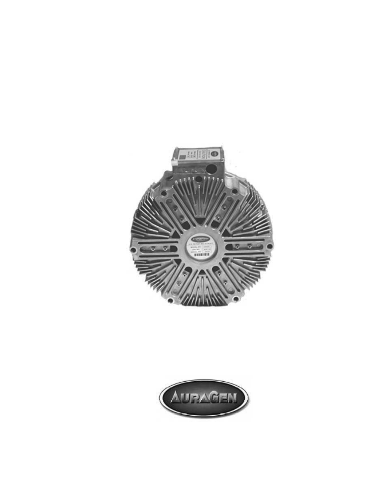
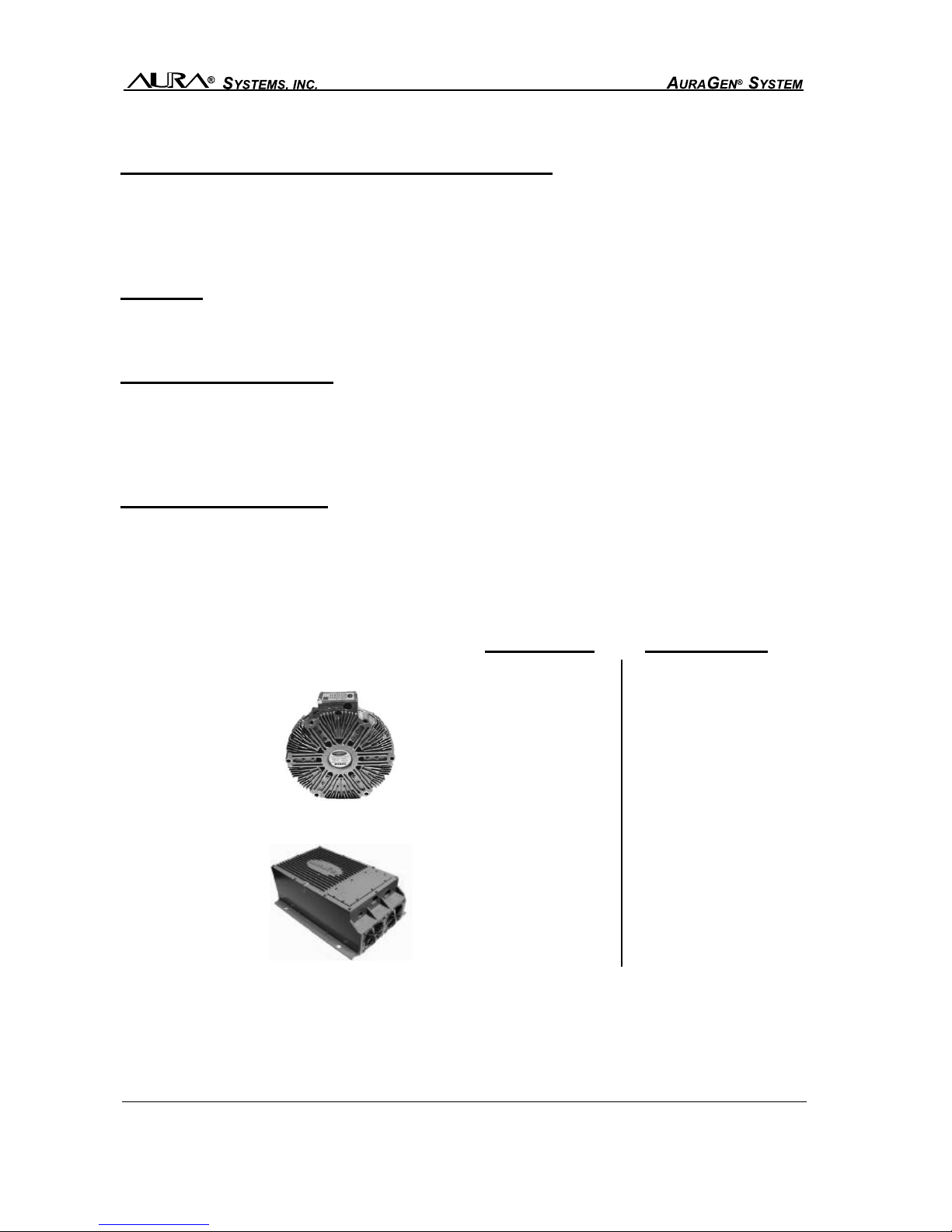
THE AURAGEN SYSTEMS
(U.S. Patents No. 5,734,217 and 6,157,175)
The AuraGen System includes:
(Also see diagrams on pages 3-5)
• Induction Power Source
• Electronic Control Unit (ECU)
• Control Panel
• Idle Control Unit (some vehicles)
• Mounting hardware and cables
(not shown)
Electronic Control Unit
Control Panel
Mechanical
Induction Power Source
Standard Inverter/Charger
Electronic
Idle Control
Induction Power Source
Dual-Tandem Generator
16000 Watts
M1120221-3, 090630
3 - Owner’s Manual
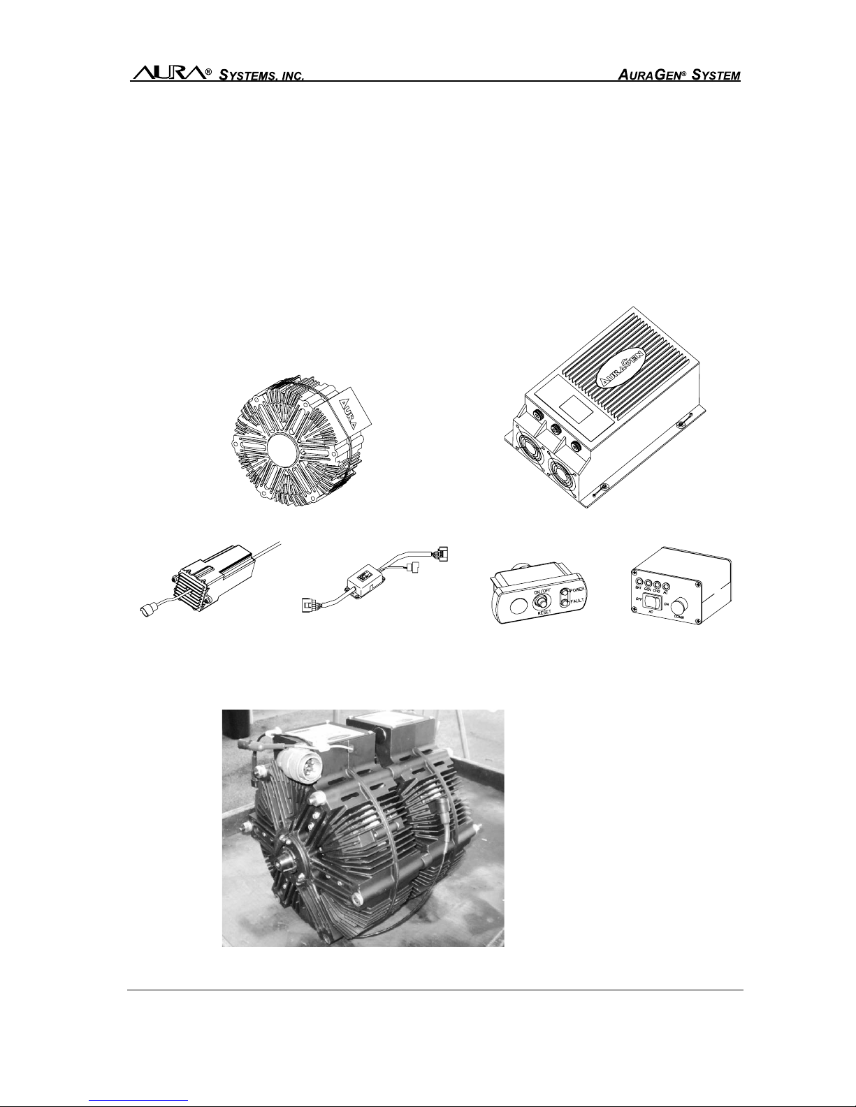
Optional Equipment Available:
• Remote Power Strip
• Manual Transfer Switch
Ask your authorized AuraGen Distributor/dealer about the optional equipment.
Manual Transfer SwitchRemote Power Strip
M1120221-3, 090630 Owner’s Manual - 4
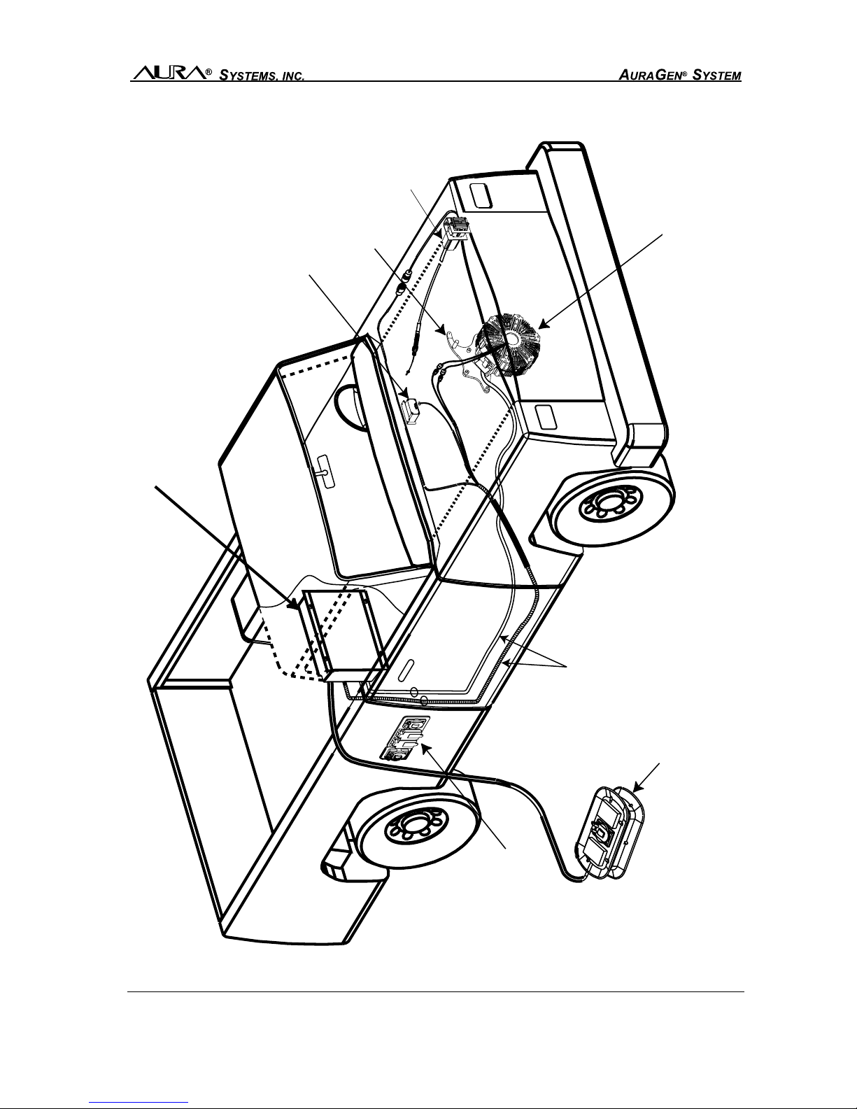
Typical Engine Mounted AuraGen System
CONTROL AND POWER
CABLES ROUTED UNDER
VEHICLE TO REAR-MOUNTED
ELECTRONIC CONTROL UNIT
REMOTE POWER STRIP
(OPTIONAL)
RECEPTACLE
OUTLET BOX
AURAGEN MOBILE
GENERATOR
THROTTLE CONTROL
(LOCATION MAY VARY)
MOUNTING BRACKET
(ENGINE AND VEHICLE
SPECIFIC)
CONTROL UNIT
ON/OFF - STATUS LEDs
(USUALLY LOCATED UNDER DASH)
ELECTRONIC CONTROL UNIT
IDLE CONTROL
(LOCATION MAY VARY)
AURAGEN INDUCTION POWER SOURCE

M1120221-3, 090630
5 - Owner’s Manual
All-AC: Provides 120 VAC power to GFI outlets and/or 240 volt outlets. An optional remote
power strip with 120 VAC and/or 120/240 VAC service is also offered.
AC/DC: Provides 120 VAC power to GFI outlets and 14 or 28 VDC connected to the vehicle
batteries. An optional remote power strip with 120 VAC service is also offered.

M1120221-3, 090630 Owner’s Manual - 6
All-DC: Provides 14 or 28 VDC to auxiliary batteries. No AC service is available.
Inverter Charger System (ICS): Provides 120 or 240 VAC and 14 or 28 VDC power with or
without engine running. An optional remote power strip with 120 or 240 VAC service is also
offered.

M1120221-3, 090630
7 - Owner’s Manual
SAFETY PRECAUTIONS
Before operating the AuraGen®, read this Owner’s Manual and become thoroughly familiar with
the equipment and its features. Operation of the equipment can be achieved safely and effi-
ciently when the unit is properly operated. Most equipment related accidents can be prevented
by following fundamental rules and precautions.
General Safety Precautions
•The AuraGen System must be installed and serviced only by AuraGen certified installers.
Consult your authorized AuraGen Distributor or Dealer or AuraGen Customer Service at (800)
909-AURA.
•DO NOT change pulley types or sizes as the Induction Power Source could exceed its 12,000
RPM limit resulting in possible component and/or system failure.
•DO NOT open or dismantle the AuraGen Induction Power Source, the Electronic Control Unit
(ECU), or any other components of the AuraGen system.
•DO NOT adjust anything on your AuraGen; see the local authorized AuraGen Distributor or
Dealer for this purpose.
•The ECU and Induction Power Source are not waterproof, and therefore each must be mounted
in an area where they will not be subjected to water splash and/or submersion. Please refer
to the AuraGen Main Installation Manual and the applicable vehicle application installation
manual for specific instructions on the mounting and installation of these components.
•Make sure the brakes on your vehicle are in good operating condition and that your vehicle is
properly and regularly maintained.
•DO NOT use this or any equipment when you are mentally or physically fatigued, or after
consuming alcohol or any mind altering substance that may affect your alertness or judge-
ment, making the operation of equipment unsafe.
•Keep a fire extinguisher nearby. Properly maintain the extinguisher and become familiar with
its use. Extinguishers rated ABC by the NFPA are appropriate for all applications. Consult the
local fire department for the correct type of extinguisher for different applications.
•Keep outlet covers down while not in use to prevent any debris from becoming lodged within
the contacts.
•DO NOT lay any output power cable on caustic chemicals or materials.
•Disconnect the vehicle battery(s), and the OEM Electronic Control Module (ECM) from the
vehicle wiring harness prior to performing welding repairs on a vehicle. The AuraGen input
fuse, input ground wire as well as the temperature sensor and RPM sensor leads need to be
disconnected if welding repairs on a vehicle are necessary.
WARNINGS
!

M1120221-3, 090630 Owner’s Manual - 8
WARNINGS
!
Exhaust Gases Are Deadly
•Provide proper ventilation of the vehicle’s exhaust. Inspect the exhaust system regularly for
leaks and to ensure that the exhaust manifold(s) is (are) secure and not warped. Do not use
exhaust gases to heat the passenger compartment.
•If the vehicle is parked in an enclosed area, you should provide proper exhaust ventilation to
the exterior of the building or facility.
•Never sleep in any vehicle with the engine running.
Moving Parts Can Cause Severe Personal Injury Or Death
•Keep hands, clothing and all other articles away from all moving parts.
Electrical Shock Can Cause Severe Personal Injury Or Death
•Use extreme caution when working with live electrical components. High voltage can cause
injury or death.
•DO NOT connect the AuraGen Electronic Control Unit (ECU) directly to any building electrical
system. Differing voltages between the AuraGen and the utility line create a potential for elec-
trocution or property damage. Connect only using a Manual Transfer Switch, supplied option-
ally by Aura. Consult a licensed electrician regarding emergency power use. Aura Systems,
Inc. recommends use of the AuraGen Manual Transfer Switch.
•Connect only UL approved devices and be sure that the equipment is in good working order.
Special Operational Precautions
•The vehicle parking brake must be engaged while using the AuraGen in a stationary
mode. (See Operating While Stationary on page 6.)
•While driving, apply vehicle brakes firmly to slow or stop during AuraGen operation.
(See details on page 10.)
M1120221-3, 090630
9 - Owner’s Manual
GENERAL OPERATING INSTRUCTIONS
All-AC, AC/DC and All-DC:
The All-AC, AC/DC and All-DC systems all use the standard control panel shown below. The
Inverter Charger System (ICS) uses a different control panel which is described on Page 9.
Read through the applicable section to become familiar with proper and safe operation of the
system installed in your vehicle.
Vehicles Without Auto Start Option
1. The standard control panel is typically located under the dashboard. To turn the system on
after the engine is started, on the control panel, momentarily press the OFF-ON switch.
2. Verify that the green POWER LED illuminates. The POWER LED will flash at first as the
system engages, then remain on continuously indicating proper operation. Any other se-
quence of LED illumination indicates a problem with the system. Refer to table on Pages 15
-16.
3. Plug in your electrical or electronic equipment, or power strip, and operate the device ac-
cording to its operator’s manual. Connect only UL approved devices or equipment and be
sure that they are in good working order.
4. To turn the system off, momentarily press the OFF-ON switch on the control panel.
Vehicles With Auto Start Option
1. The AuraGen Control Panel is typically located under the dashboard.
2. When the engine is started the AuraGen system will automatically start.
3. Verify that the green POWER LED illuminates. The POWER LED will flash at first as the
system engages, then remain on continuously indicating proper operation. Any other se-
quence of LED illumination indicates a problem with the system. Refer to table on Pages 15
-16.
4. Plug in your electrical or electronic equipment, or power strip, and operate the device ac-
cording to its operator’s manual. Connect only UL approved devices or equipment and be
sure that they are in good working order.
5. To turn the Auto Start function off, depress and hold the OFF-ON button for 3-4 seconds; the
green light will turn off.
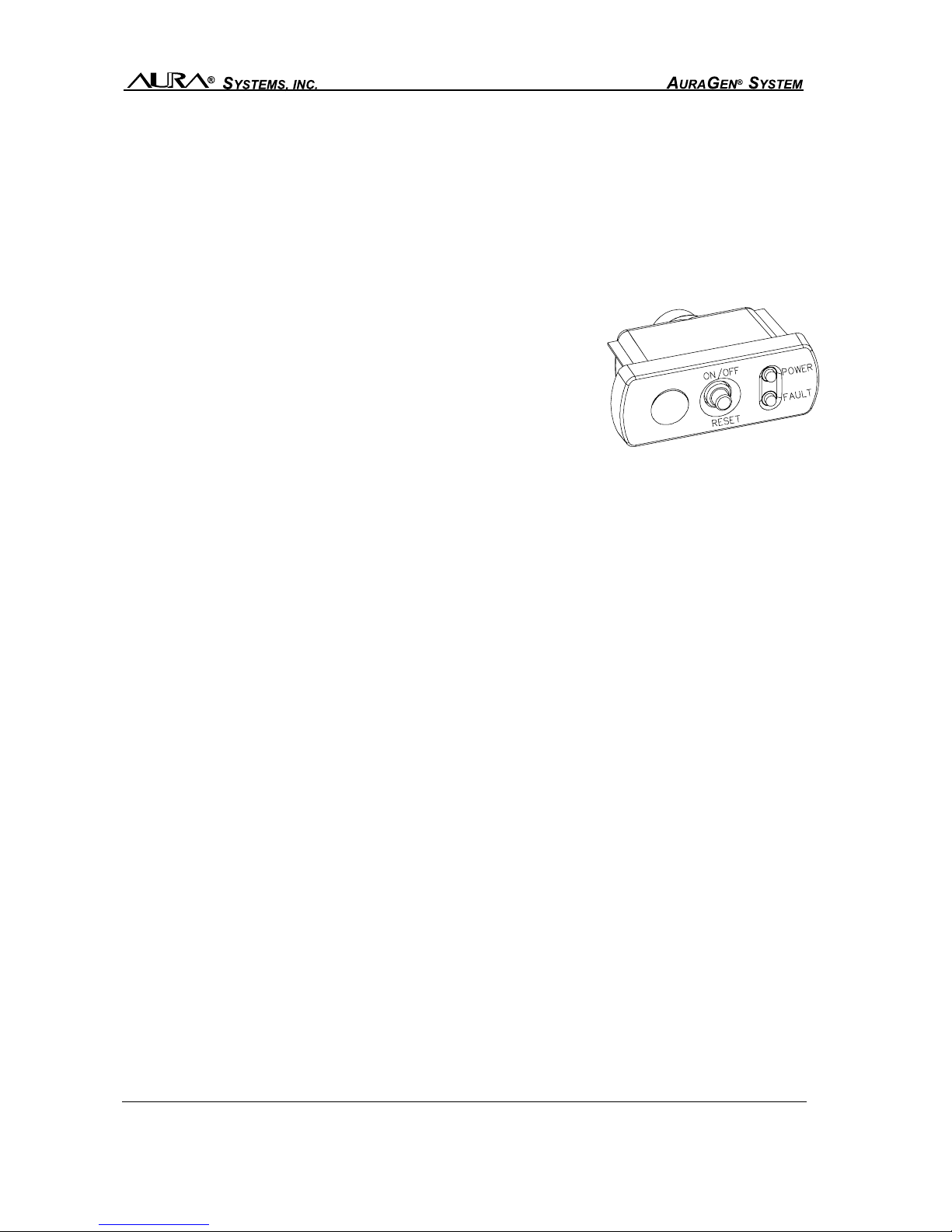
The standard control panel allows you to turn the AuraGen sys-
tem on or off, reset the system if required, and has red and
green LED lights to indicate system and component status.
Standard Control Panel
M1120221-3, 090630 Owner’s Manual - 10
Vehicle Engine Running - AC Control Switch Off
The ICS will automatically provide DC power to charge the auxiliary batteries when the engine is
started and the ICS has powered-up. The GEN and CHG LED lights will be GREEN, and the
BAT light will be GREEN, YELLOW or RED depending on the level of charge in the auxiliary
batteries. In this mode the AC output is not ON.
Vehicle Engine Running - AC Control Switch On
In this mode, the ICS will automatically charge the auxiliary batteries and the AC output is ON and
supplying AC voltage. In addition to normal charging indications, the AC LED should be GREEN.
Vehicle Engine Off - AC Control Switch Off
All components in the ICS are off. With the vehicle ignition switch turned on, the control panel BAT
LED will be GREEN, YELLOW or RED, depending on the charge level of the auxiliary batteries.
Vehicle Engine Off - AC Control Switch On
With the AC control switch ON and sufficient auxiliary battery charge available, the AC output is
ON and supplying AC voltage. The AC LED light should be GREEN and the BAT light either
GREEN or YELLOW. If the auxiliary batteries have an insufficient level of charge, the ICS will not
power up, and the BAT and AC LEDs will be RED. If the battery charge is too low, the engine
must be started to charge the auxiliary batteries.
Typical ICS Operation
A typical example of ICS use would be that of a motor home being driven with the AC control
switch OFF. While driving, the auxiliary batteries are being charged. If AC appliances were
needed, the operator would turn the AC control switch to the ON position, and after a few mo-
ments, the system will begin to supply AC power. In this mode the ICS will simultaneously provide
power to charge the auxiliary batteries, and by priority, run the AC appliances. When the engine
is stopped, the ICS will provide DC power from the auxiliary batteries to the inverter to seamlessly
supply the appliances with AC power. When the AC switch is moved to off, the ICS system will
power-down and remain in standby operation for 10 minutes.
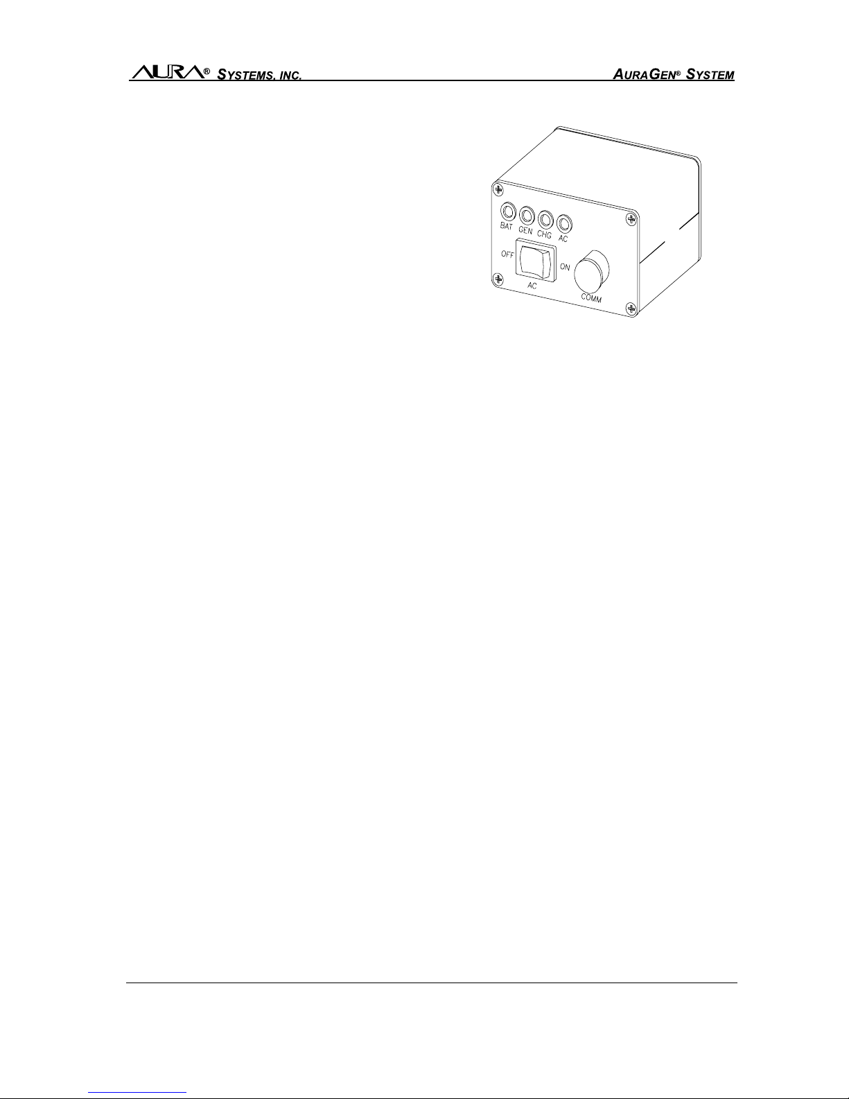
Inverter Charger System:
The Inverter Charger control panel, typically located un-
der the dashboard, has a two-position switch which al-
lows you to turn the AC power ON and OFF. It has four
LED lights labeled BAT for auxiliary battery(s), GEN for
AuraGen, CHG for battery charger, and AC for AC out-
put. All LEDs are system-active dependent and combine
to indicate ICS and component operational status. For
LED light indications other than those defined as normal,
see the Problem Troubleshooting Guide on Pages 17-
18. Inverter Charger Control Panel
M1120221-3, 090630
11 - Owner’s Manual
OPERATION WHILE STATIONARY
1. Park your vehicle in the appropriate position for your application.
2. Place the transmission in park (automatic) or neutral (manual) and engage the parking
brake. It is also a good idea to use wheel chocks to prevent accidental movement of the
vehicle.
3. When the parking brake is engaged, the system will automatically default to “stationary” or
Park mode. Depending upon the vehicle and engine type, the engine RPM will increase to a
constant level similar to engagement of an air conditioning compressor . If the AuraGen is
operated at very high power levels for extended periods of time, the engine RPM will in-
crease by up to 200 RPM to compensate for the increase in system temperature. Depend-
ing upon the vehicle and engine type, to obtain the maximum power output, it is very impor-
tant that the parking brake be engaged when operating in stationary mode.
OPERATION WHILE DRIVING
When the parking brake is not engaged, the system automatically defaults to the “drive” mode.
Certain vehicles may have limited power or be disabled in drive mode. In drive mode certain
vehicles will have a reduced engine idle from the Stationary Operation Mode while others may
have little or no change to the engine idle. The vehicle can be driven normally with little or no
impact on drivability.
WARNING: Depending upon the vehicle type, during high power demand, the “feel” of the ve-
hicle may be slightly different when the vehicle is slowed or stopped (such as creeping slowly at
a traffic light).
HOW TO OBTAIN SERVICE
Should your AuraGen system ever need service, visit your authorized AuraGen Distributor or
Dealer from whom it was purchased. For information on a authorized repair facility near you,
please contact AuraGen Customer Service/Product Support at 800-909-AURA. NOTE: All in-
stallation, service and repairs must be performed by an authorized AuraGen installer.
Do not return products without prior authorization. Contact your authorized AuraGen Distributor
or Dealer for complete return procedures.
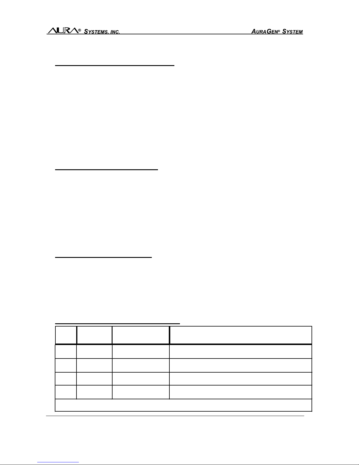
AURAGEN OPTIONAL EQUIPMENT
ITEM
NO.
PART
NUMBER OPTIONS DESCRIPTION
1 900-020 Remote Power Strip 5 kW; 20' lightweight extension with 120 and 240 volt
outlets with water resistant covers (AC only)
2 900-021 Remote Power Strip 5 kW; 20' lightweight extension with two 120 VAC, 42
amp outlets with water resistant covers (AC only)
3 900-022 Remote Power Strip 8.5 kW; 20' lightweight extension with 120 and 240
VAC outlets with water resistant covers
(
AC onl
y)
4 900-040 Manual Transfer
Switch
Manual Transfer Switch to allow power from AuraGen
to power your home or business.
Please discuss these options and your present and future mobile power needs with your local
AuraGen Distributor or Dealer.

M1120221-3, 090630 Owner’s Manual - 12
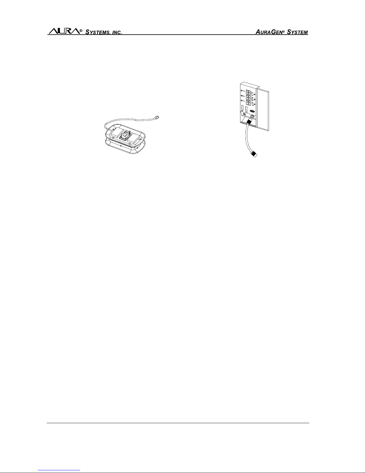
Options 1- 3 - Remote Power Strip:
The Remote Power Strip provides power outlets mounted at the end of 20-foot power cables.
The extension power cable can be connected by plugging in and screwing the connector at the
end of the cable into the ECU.
Option 4 - Manual Transfer Switch:
This includes the Manual Transfer Switch box. This option is very useful when you need to have
an auxiliary power source on if commercial power to your home or business is not available. A
transfer switch MUST be used to couple an auxiliary power source to a house or any building
connected to the commercial power grid.
The Manual Transfer Switch eliminates safety concerns by offering an indoor/outdoor, rain tight
surface mount box. The double-throw switch action of each transfer switch circuit keeps the
AuraGen system isolated from the utility line at all times. This eliminates the danger of backfeeding
the utility lines and potentially causing injury to repair crews, as well as preventing utility power
from feeding into the AuraGen system, causing property damage or personal injury.
This transfer switch must only be installed by a qualified/licensed electrician who has a thorough
knowledge of all applicable electrical and building codes.
PUTTING YOUR AURAGEN SYSTEM TO USE
Your AuraGen System is a useful mobile source of 120/240 volt AC and 14/28 volt DC power, as
specified from your AuraGen model. This means, within the limitations of its generating capacity,
you can use it to power most electrical appliances, machines, or equipment. Furthermore, the
AuraGen is a reliable and clean power source, even better than commercial power. Any type of
electrical equipment, digital, diagnostic, as well as power tools can be operated simultaneously.
Review the system specifications on pages 19 through 22 to determine your AuraGen system’s
power output and capabilities.
M1120221-3, 090630
13 - Owner’s Manual
This means you can use it in a variety of different ways. You can even use the system while
driving, making it ideal for emergency or recreational vehicle use. The AuraGen system is also
an ideal source of power to run tools at locations that don’t yet have commercial power available.
The system is a perfect way to bring the convenience of high quality power to remote locations.
Most importantly, your AuraGen system can also serve as a reliable source of emergency power
for your home or business in the event of a commercial power failure. For this application, your
home or business should be outfitted with the optional AuraGen Manual Transfer Switch (See
Optional Equipment on page 10 and 11).
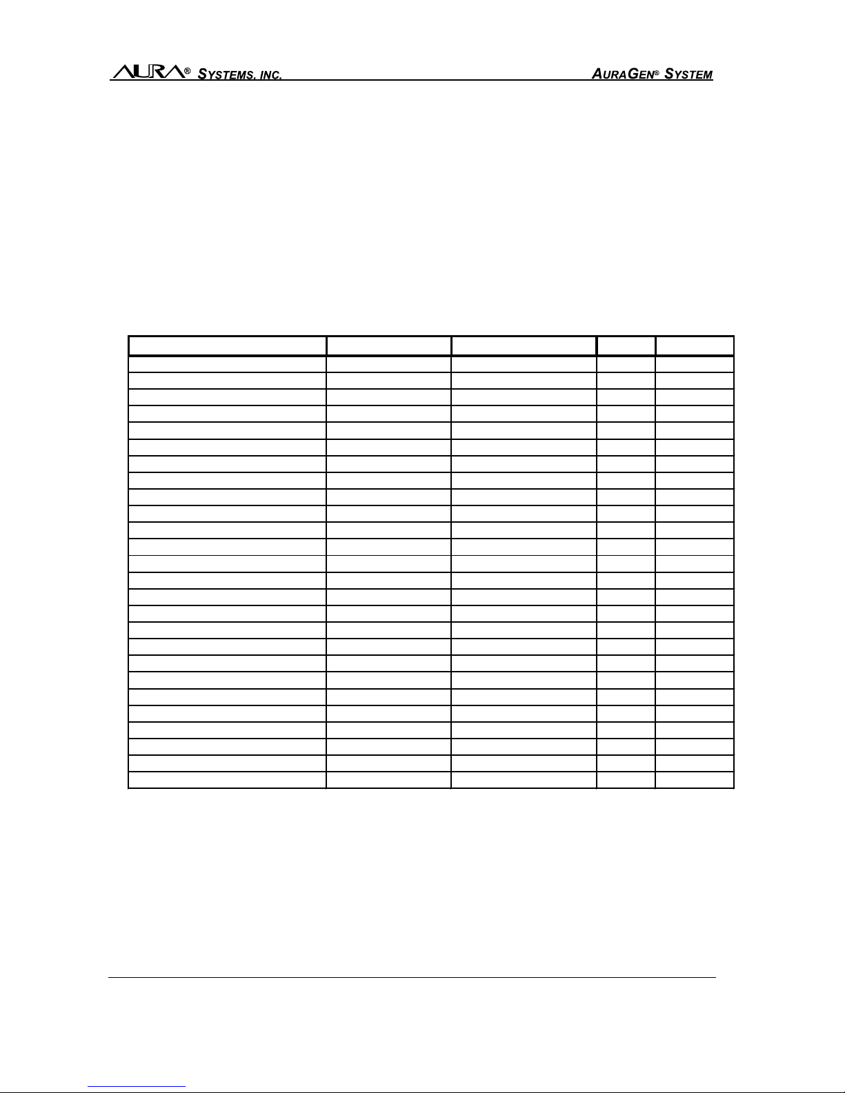
TYPICAL AURAGEN APPLICATIONS
POWER CAPACITY
While your AuraGen system can serve as a reliable substitute for commercial power, it can only
do so within the limitations of its maximum output capacity. For example, the G5000 system
provides standby power of up to 6,000 watts with surge capacity of 7,200 watts for 2 seconds.
This output is available from 120 volt AC and 240 volt AC circuits. Each 120 volt circuit has a
maximum current capacity and is electronically current limited to 21 amps. This means the maxi-
mum power load on either 120 volt circuit cannot exceed 2,520 watts. The 240 volt circuit also
has a 21 amp current limited maximum current capacity, which means its maximum power load
cannot exceed 5,000 watts. Just as a circuit breaker in your house will trip if you connect too
APPLIANCE/TOOL COMMERCIAL CONSTRUCTION HOME LEISURE
Fresh Air Blower X X
Plastic Pipe Fusion X X
Signboards X X
Water Pump X X
Pipe Threader X X
Large Light Banks X X
AC Welder X X X
Air Compressor X X X
Circular Saw X X X
Electric Drill X X X
Electric Chain Saw X X X
Pressure Washer X X X
Winches X X X
Paint Sprayer X X X
Personal Computer X X X X
Outdoor Trimmer X X
Electric Leaf Blower X X
Air Conditioner X X X
Color TV / Monitors X X X
Freezer X X
Refrigerator X X X
Space Heater X X X
Traffic Signals X
Fire/Rescue Equipment X
Broadcast Equipment X
Laser Measuring Equipment X X X
M1120221-3, 090630 Owner’s Manual - 14
many appliances to any one circuit, the internal electronics in the AuraGen ECU will do the same.
Please use caution when connecting appliances/tools that have high start-up amperage. Verify
with the manufacturer to make sure the peak current surge will not exceed your specific AuraGen’s
capabilities.
Each of the three output circuits can individually supply up to 21 amps of output current, but you
cannot draw the maximum current from all three output circuits at the same time. The
total output power from all three circuits cannot exceed the rated output of the G5000 which is
6,000 watts for up to 20 minutes (standby). If your AuraGen model is a G8500, you can produce
up to 8,000 watts of AC power continuous or 8,500 watts for up to 20 minutes (standby). When
using the AuraGen system, be careful not to overload any of the output circuits individually, or the
system as a whole. To determine your AuraGen model’s power capabilities, see the AuraGen
System Specifications on pages 20 through 28.
If in the event that the ECU automatically shuts down the system because of a prolonged over-
load, the system can be reset from the AuraGen Control Panel.
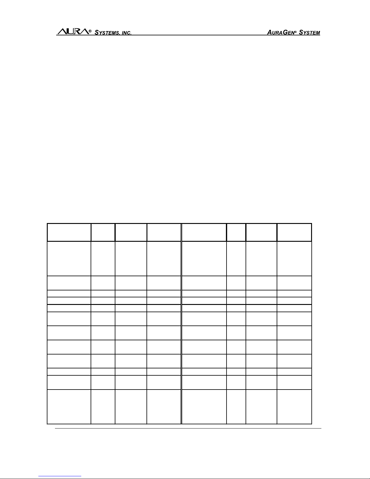
WATTAGE REQUIREMENTS FOR TYPICAL APPLIANCES AND TOOLS
POWER = VOLTAGE X CURRENT
THUS
CURRENT CAPACITY = POWER
VOLTAGE
APPLIANCE TYPE WATTS
(RUNNING)
WATTS
(STARTING) APPLIANCE TYPE WATTS
(RUNNING)
WATTS
(STARTING)
Coffee maker (Typical) 1750 same Furnace blower 1/8 hp 300 500
Elec. Range 6" element 1500 same (Gas or fuel oil) 1/6 hp 500 750
8" element 2100 same 1/4 hp 600 1000
Oven 6000* same 1/3 hp 700 1400
Microwave oven 1200 same 1/2 hp 875 2350
Television B&W 100 same Garage door opener 1/4 hp 550 1100
(Solid state) Color 300 same 1/3 hp 875 2300
Radio 50-200 same Electric blanket 400 same
Air conditioner 3000 varies Computer 100-250 same
Refrigerator/freezer 800 2300 Portable dehumidifier 650 800
Shallow well pump 1/3 hp 750 1400 Vacuum cleaner Up to same
1/2 hp 1000 2100 2200
Sump pump 1/3 hp 800 1300 Lights shown same
1/2 hp 1050 2150 on bulb
Dishwasher (cool dry) 700 1400 Toaster (2 slice) 1050 same
(hot dry) 1450 2900 (4 slice) 1650 same
Cloths dryer (gas) 700 1800 Hair dryer (typical) 300-1200 same
(electric) 5750* 7000* Iron 1200 same
Automatic washer 1150 2300 Electric fan 200 600
Hedge Trimmer 450 900 Lawn edger 750 1500
Leaf blower 600 1200 String trimmer 500 1000
Chain saw 800-1500 3100 Electric drill 1/2" 350-1000 1500
Orbital sander 0700
Paint sprayer 600 750
Soldering gun 0same
Circular saw 500-1000 2000
Drain cleaner 300 600 Router 900-1100 2400
Compressor 3000 varies

M1120221-3, 090630
15 - Owner’s Manual
GENERAL INSPECTION
Periodically check the AuraGen serpentine belt for signs of wear, fraying, and proper tension.
Contact your authorized distributor/dealer if belt shows signs of wear. Also, visually inspect the
Electronic Control Unit (ECU) to ensure there is nothing obstructing the airflow around the unit.
PROBLEM TROUBLESHOOTING
Refer to the troubleshooting guides provided on the following pages. The solutions are num-
bered by the most likely to the least likely. As an example, a Gen Temp Sense Open is more likely
to be an open connector before an open sensor.
See pages 16 and 17 for the All-AC, All-DC, and AC/DC systems, and pages 18 and 19 for the
ICS.
This manual suits for next models
4
Table of contents


