AURATON RTH User manual

User’s Manual
RTH
www.auraton.pl
OFF
ON
IN
OUT
ALARM
RESET

2
Congratulations on your purchase of a modern AURATON RTH receiver
installed at the heating or air-conditioning device.
Operation with load up to 16A
The AURATON RTH receiver has been equipped with the
transmitter which may work with load up to 16A. Low-spark
technology of switching the voltage system causes minimal wear
of the transmitter's contacts.
Interruption-free communication between devices.
AURATON RTH communicate on the 868MHz frequency. Very short
encrypted transmission packets (ca. 0.004s) provide efficient and
interruption-free operation of the device.
LED diodes
LED diodes inform in a clear manner about the device operating
status.
ON / OFF cycles memory algorithm
The AURATON RTH receiver is equipped with a unique algorithm of
ON- OFF cycles analysis. The whole heating cycle from the last 24h
is saved in the memory of the RTH receiver. In the case of loss of
communication with the temperature controller and/or the T-2
thermometer, the RTH receiver will automatically perform the
remembered cycle of activations / shutdowns from the last 24h. It
gives time to restore the transmission (removal of interruption) or
repair the controller and/or the T-2 thermometer without
significant thermal comfort deterioration in the controlled facility.
Basic product characteristics

3
cable tie clamp
control connection terminal
(a terminal for fastening a two-core
cable of the heating or air conditioning
device to be controlled
button for deregistering
already paired devices
button for pairing devices
with the RTH receiver
LED indicating operation
of the device
cable tie clamp
power supply terminal
~230 VAC
legend
The LED light’s green – the output device is off (the contacts
COM and NC are closed).
The LED light’s red – the output device is on (the contacts COM
and NO are closed).
The LED flashes green – the RTH receiver awaits the device
to be paired.
The LED flashes red – the RTH receiver awaits the device
to be deregistered.
The LED flashes alternating red and green:
ALARM - the RTH receiver has lost connection with one of the
paired devices.
RESET - receiver deregisters all previously paired devices.
Legend - description of LED signalling
hole for fastening the receiver
to the wall with a screw
hole for fastening the receiver
to the wall with a screw
Description of the AURATON RTH receiver
The receiver is installed on the heating or air conditioning device and can
operate under the load of 16 A.
~230V AC

4
3. Connect the heating device to the
control connection terminals of the
AURATON RTH receiver.
Proceed in accordance with the service
manual of the heating device. Most
commonly, the COM (common) and NO
(normally open) terminals.
4. Connect power supply conductors to the
power supply terminals of the AURATON
RTH receiver, observing safety rules.
Fastening the RTH receiver
1. Take off protective covers from the lower
and upper part of the AURATON RTH
receiver.
2. Take off cable tie clamps from the lower
and upper part of the AURATON RTH
receiver.
protective cover
cable tie clamp
NOTE: When installing the AURATON RTH
receiver its power supply must be
disconnected. It is recommended that the
installation is performed by a qualified
specialist.
~230V AC 5. After connecting the conductors, they
must be secured with the cable tie
clamps and reinstall protective covers of
the AURATON RTH receiver.
NOTE:
The permanent electrical system
of a building must include a breaker
and an overcurrent protection.

5
To fasten the AURATON RTH receiver to the wall:
1) Remove protective covers from the lower and upper part of the regulator.
(See chapter: “Fastening the RTH receiver”).
2) On the wall, mark the location of holes for fastening screws.
3) In marked places, drill holes of a diameter corresponding to the bundled
wall plugs (5 mm).
4) Insert wall plugs into the drilled holes.
5) Screw in the RTH receiver to the wall with screws, making sure they hold
thereceiver securely.
Fastening the RTH receiver to the wall
NOTE: If the wall is wooden, there is no need to use wall plugs. In such a case,
drill two holes 2.7 mm in diameter instead of 5 mm, and screw
the screws directly into the wood.
NOTE:The RTH receiver cannot be placed in metal containers
(e.g. an assembly box, a metal enclosure of a heater) in order to not to
interfere with its operation.
AURATON RTH
hole for fastening
the receiver to the wall with a screw
hole for fastening
the receiver to the wall with a screw

6
First start-up of RTH receiver
The first connection of the RTH receiver to the supply network will result in
the receiver going into the "association" mode for 120 seconds. It is
signalled by LED diode flashing with a green light.(see chapter: "Associating
device with RTH receiver" and "RESETTING - Signing out all devices assigned
to receiver).
Note: The RTH receiver purchased in the set with the temperature controller
already has an associated device and the above case will not take place.
Associating device with RTH receiver
OFF
ON
IN
OUT
ALARM
RESET
LED
In order for the AURATON RTH receiver to operate correctly it must be first
"associated" with one of the system devices (e.g. the AURATON T-1
temperature controller ).
1.Associating a new device with the receiver is
initiated by pressing the left association button
(green triangle - ) on the receiver and
pressing it for at least 2 seconds, until the LED
diode starts flashing with a green light, then we
release the button.
Note: The receiver is waiting for association for
120 seconds. seconds. After this time it will
automatically return to normal operation..
2.When the LED diode of the receiver flashes with a green light, press the
"association button" on the device that you want to associate and hold it for
at least 2 seconds (precise association manual is attached to each device).
3.Correct completion of association is signaled by the stop of flashing with
a green light of the LED diode on the receiver and the receiver going into
normal operation.
In the case of an error during association, steps 1 and 2 should be repeated. At
subsequent errors, sign out all devices by RESETTING the receiver (see chapter
"RESETTING-Signing out all devices assigned to receiver") and try to associate
the device again.
Note: Once added device cannot be again associated with this receiver, since it
is already saved in the receiver memory.

Signing out device from RTH receiver
1.Signing out the device from the RTH
receiver is initiated by pressing the right
sign out button (red triangle - ) on the
receiver and pressing it for at least 2 sec,
until the LED diode starts flashing with a red
light, then we release the button.
Note: The receiver is waiting for signing out
of the device for 120 seconds. After this time
it will automatically return to normal
operation.
7
OFF
ON
IN
OUT
LED
2.When the LED diode of the receiver flashes with a green light, press the
"association button" on the device that you want to sign out and hold it
pressed for at least 2 seconds (precise signing out manual is attached to
each device)..
3.Correct completion of signing out is signalled by the stop of flashing with a
red light of the LED diode on the receiver and the receiver going into normal
operation.
In the case of an error, steps 1 and 2 should be repeated.
RESETTING - Signing out all devices
assigned to receiver
In order to sign out all devices associated with the
receiver press and hold at the same time both
association and sign out ( and ) buttons for at
least 5 seconds until signalling of the LED diode
changes to alternate flashing in colours green and
red. Then release both buttons.
Correct completion of signing out of all devices is
signalled after approximately 2 seconds by
signalling change to green and then its fading.
AURATON RTH
OFF
ON
IN
OUT
ALARM
RESET
Note: If after RESETTING we disconnect the receiver from the power supply
and then we connect the power supply again, the receiver will
automatically go into the "association" mode, just as at the first start-up.

RTH receiver operation
with heating device
8
After switching on the power supply the transmitter of the RTH AURATON
the receiver is always activated until it receives information from associated
devices.
Cooperation of receiver with AURATON T-1 regulator and/or
AURATON T-2 thermometer
Controlling the temperature in the receiver is based on two-state signal
algorithm (turn on /turn off) which makes use of one or two sensor
elements:
heating device AURATON RTH
A simplified schematic
of connecting the AURATON RTH
receiver with the heating device
The T-1 controller enables setting the temperature and/or its
controlling.
The T-2 thermometer gives information about the current
temperature without the possibility of its manual change.
AURATON T-1
Wireless
temperature
(sold separately)
Basic configuration of devices
AURATON T
-2
AURATON T-2
Wireless thermometer
(sold separately)
AURATON H-1
Window handle
(sold separately)
AURATON RTH
Receiver connected
to the heating device
AURATON RTH
OFF
ON
IN
OUT
ALARM
RESET
Additional system devices
AURATON T
-2

A) Manual setting - associating the T-1 controller with the RTH receiver we
have a possibility to manually set the temperature and control it in the
place of fastening the T-1 controller.
B) Remote setting - if to the same RTH receiver we additionally associate
the T-2 thermometer, the T-1 controller will retain the ability to set the
temperature, however, its control will be implemented only by the
associated T-2 thermometer. This enables controlling the temperature in
a room other than the one in which the T-1 controller is placed.
Example: We want the "baby room" to always have the temperature of
22°C, while we do not want the children to have a possibility to change the
temperature, we install the T-2 thermometer in the "baby room" and the
T-1 controller for instance in the kitchen. Thanks to such solution the
"baby room" will always have a temperature of 22°C regardless of the
temperature fluctuations that occur in the kitchen.
C) factory setting (20°C) - If with the RTH receiver we associate only the T-2
thermometer it is not possible to manually set the temperature and the
RTH receiver will maintain the factory setting of 20°C.
9
ATTENTION!
1. The order of associating the T-1controller and T-2 thermometer is very
important. If we want to pursue a remote setting , in the first place
associate the T-1 controller with RTH receiver and then the T-2
thermometer. Reverse association will result in automatic signing out of
the previously associated T-2 thermometer.
2. The RTH receiver may work only with one T-1 controller and/or one T-2
thermometer. Associating a new T-1controller will result in signing out of
the previously associated T-1controller and T-2 thermometer. Associating a
new T-2 thermometer will result in signing out of the previously associated
T-2 thermometer.

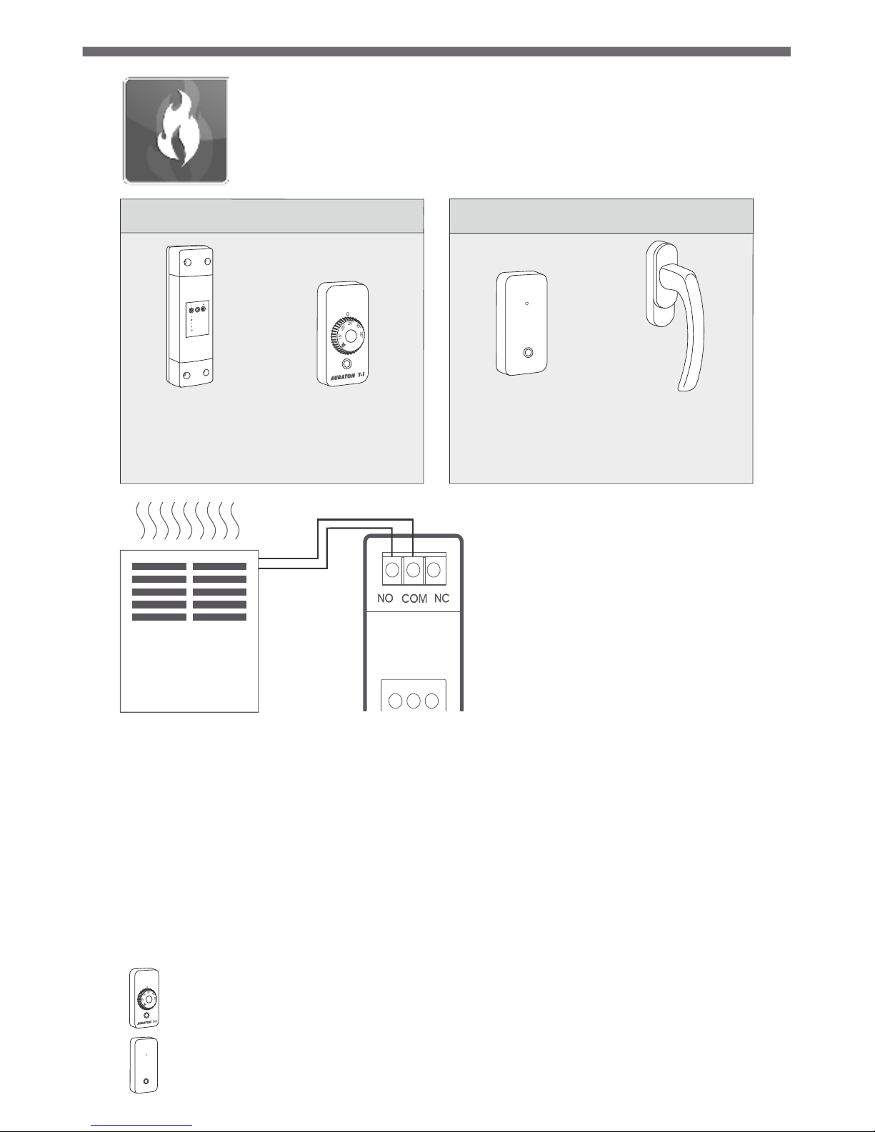
Cooperation with AURATON T-1 controller and/or T-2
thermometer and AURATON H-1 handles
When the RTH receiver has no associated H-1 handle the transmitter is by
default controlled by the associated T-1controller and/or T-2. thermometer.
When we associate at least one H-1 handle with the RTH receiver, controlling
the transmitter will proceed as follows:
A) Window closed or unsealed (micro ventilation).
When we associate H-1 handles with the receiver and all windows are
closed or unsealed, the transmitter still performs the setting from the
associated T-1 with the receiver controller and/or T-2 thermometer.
B) Window ajar.
When we slightly open at least one window, the temperature in the RTH
AURATON receiver of the T-1 controller will be decreased by about 3°C This
state will last until the time of closing or unsealing all windows assigned to
the RTH receiver.
Example: On the T-1 controller we have set the temperature of 21°C Then
we slightly open the window with an associated H-1 handle. The RTH
receiver will maintain the temperature of 18°C in the room.
C) Window open.
When we open the window with an associated H-1 handle for longer than
30 sec, the transmitter in the RTH AURATON receiver will be turned off and
the heating device will also turn off. If all assigned windows once again will
be in a position different than open, the RTH receiver will return to normal
cooperation with the T-1 controller and/or the T-2 thermometer after time
not shorter than 90 seconds from turning off of the transmitter. This is an
intentional delay so as to prevent too rapid changes of heating devices
between ON-OFF position. However, if the temperature in the room falls
below 7°C, regardless of the position of windows, the transmitter in the
receiver will switch on activating the heating device to prevent the rooms
from freezing.
D) Loss of signal.
When the RTH receiver loses signal from the associated H-1 handle
(3 subsequent lost transmissions), it changes the status of this window to
closed. After restoring the transmission, the H-1 handle or window
position sensor once again are correctly read by the RTH receiver.
10
Note: One AURATON RTH receiver can operate max. 25 handles.

11
AURATON RTH
receiver connected
to air-conditioner
AURATON H-1
window handle
to be purchased
separately
RTH receiver operation
with air-conditioning device
Basic device configuration
A simplified schematic
of connecting the AURATON RTH
receiver with air-conditioning
device
air-conditioning
device
~230 VAC
AURATON RTH
NL
Max 16A
Cooperation of the RTH receiver with the H-1 handles
without the T-1 controller and the T-2 thermometer
A) Air-conditioning controlling.
In order for the RTH receiver to be able to control air-conditioning:
it cannot be the associated with any T-1 controller or T-2 thermometer,
it must be associated with at least one H-1 handle or window position
sensor.
AURATON RTH
OFF
ON
IN
OUT
ALARM
RESET

Upon fulfillment of the above requirements, the RTH receiver goes into
automatic mode of controlling the air-conditioning. If we connect,
through the transmitter, the power supply circuit for air-conditioning
devices and open or slightly open any window with an associated H-1
handle or window position sensor for longer than 30 sec, the transmitter
will turn off the air-conditioning device.
If all windows with an associated H-1 handle or window position sensor
once again will be in a position other than open or ajar, the RTH receiver
after time not shorter than 90 seconds from deactivating the transmitter
once again will activate the transmitter and the air-conditioning device.
This is an intentional delay so as to prevent too rapid changes of air
conditioning devices between ON-OFF position, which can lead to
compressor damage.
B) Loss of signal.
When the RTH receiver loses signal from the associated H-1 handle or
window position sensor (3 subsequent lost transmissions), it changes
the status of this window to closed. After restoring the transmission once
again the sensor is correctly read by the receiver.
Note: associating the T-1 controller or the T-2 thermometer automatically
changes the way of operating of the RTH receiver to controlling the heating
device.
12
Signalling operation and receiving
data package
Each reception of the radio transmission by the AURATON RTH receiver
from associated devices is signalled by a temporary change of the LED
diode colour to orange. After activating the transmitter the LED diode is
red, after shutting down the transmitter the LED diode is green.

Unusual situations
13
źAfter the loss of 3 subsequent transmissions (after 15 minutes) from the
T-1 controller and/or T-2 thermometer signaling the failure will take
place on the RTH receiver (continuous LED flashing alternately with red
and green light). Until the removal of the problem the RTH receiver goes
into the remembered ON/OFF cycle from the last 24h.
źWhen both signals come back (T-1 controller and T-2 thermometer), the
error is deleted and the receiver goes into normal operation.
źAs soon as the signal from the T-2 thermometer returns, the receiver
uses the last remembered setting and maintains it, still signalling failure.
źWhen we have H-1 handles or window position sensors, T-2
thermometer and T-1 controller (temperature is measured by the T-2
thermometer) associated with the receiver, maintaining the operation
cycle from the last 24h will take place only after loss of signal from the T-2
thermometer. When there is no signal only from the T-1 controller the
RTH receiver automatically maintains the most recently remembered
setting of the T-1 controller but also signals failure.
źWhen we have only H-1 handles associated with the RTH receiver and
associated the T-2 thermometer without the T-1 controller, the RTH
receiver will maintain constant temperature factory set at 20°C. If we
slightly open any window with associated, H-1 handle, the temperature
of 17°C will be maintained. If any window with associated H-1 handle
will be opened the RTH receiver will turn off the heating device, but it will
activate it again if the temperature falls below 7°C.
źSwitching of the transmitter is synchronized with the course of power supply
network 230 V so as to ensure that short circuit and opening of contacts of the
transmitter always proceeds close to the passage of the course of system voltage by
zero. It prevents the formation of an electrical arc and significantly increases
durability of the transmitter.
źThe AURATON RTH receiver is equipped with a unique algorithm of ON-OFF cycle
analysis. The whole heating cycle from the last 24h is saved in the memory of the
RTH receiver. In the case of loss of communication with the T-1 controller and/or the
T-2 thermometer, the RTH receiver will automatically perform the remembered
ON/OFF cycle from the last 24h. It gives time to restore the transmission (removal of
interruptions) or repair the T-1 controller and/or the T-2 thermometer without
significant thermal comfort deterioration in the controlled facility.
Unique features of AURATON T-1 RTH

Additional information and comments
źWireless devices associated with the RTH receiver should be installed
minimum 1 meter away from the RTH receiver (a signal from the
transmitters that is too strong may cause interruptions).
źBetween the next turning off and on of the transmitter at least
30 seconds must pass.
źTransmission of data from the T-1 controller to the RTH receiver happens
at each change of the environment temperature by 0.2°C. When the
temperature does not change, the T-1 controller sends data every
5 minutes (it is reflected by LED diodes flashing on the T-1controller and
LED diodes flashing on the RTH receiver - with an orange light)
źAt power supply failure the RTH receiver will be deactivated. After
restoration of power supply the heating device will be automatically
activated and the RTH receiver will be expecting the nearest signal from
associated transmitters (this signal should arrive not later than within
5 minutes after power supply restoration). After receiving the signal the
RTH receiver will go into normal operation.
źDo not place the RTH receiver in metal casings (e.g.. installation boxes,
metal furnace casings) so as not to disturb the controller operation.
14
źSwitching of the transmitter is synchronized with the course of supply
network 230 V so as to ensure that short circuit and opening of contacts
of the transmitter always proceed in the area of the course of passage
of voltage system by zero. It prevents the formation of an electrical arc
and significantly increases the durability of the transmitter.
źThe AURATON RTH receiver is equipped with a unique algorithm of
ON-OFF cycle analysis. The whole heating cycle from the last 24h is saved
in the memory of the RTH receiver. In the case of loss of communication
with the T-1 controller and/or the T-2 thermometer, the RTH receiver will
automatically perform the remembered ON/OFF cycle from the last 24h.
It gives time to restore the transmission (removal of interruptions)
or repair the T-1 controller and/or the T-2 thermometer without
significant thermal comfort deterioration in the controlled facility.
Unique features of AURATON T-1 RTH

Disposing of device
The devices are marked with a symbol of a crossed out container
for waste. According to the European Directive 2002/96/EC and
the Act on electrical and electronic equipment such marking
informs that this equipment, after period of its use cannot be
put along with other waste from the household.
The User is obliged to hand it over to the electronic and electrical
equipment waste collection point.
Technical specifications
Work cycle: daily
Verification of operation condition: LED diode
Maximum load current ~16A 250 VAC
for transmitter contacts:
RTH power supply: 230 VAC, 50 Hz
Radio frequency: 868 MHz
Range of operation in a typical building, with a standard
with wireless devices: structure of walls - ca. 30 m, in an open
area - up to 300 m
IP 20
15

www.auraton.pl
Table of contents
Other AURATON Receiver manuals
Popular Receiver manuals by other brands

MaestroShield
MaestroShield EL03-10MR10 Wiring instructions

Technics
Technics SA-GX390 operating instructions

SOMFY
SOMFY Lighting Receiver io installation guide

Nice
Nice TT2N Instructions and warnings for installation and use

Extron electronics
Extron electronics MTP 15HD A Series Setup guide

Pioneer
Pioneer SC-LX81 operating instructions