manuals.online logo
Brands
  1. Home
  2. •
  3. Brands
  4. •
  5. FrSky
  6. •
  7. Receiver
  8. •
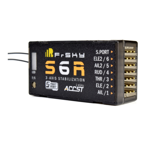
  9. FrSky S6R User manual

FrSky S6R User manual

1111
F
...
5ii
1-'1
!::1
Instruction
manual
for
FrSky
S6R
1
S8R
Overview
SmartPort -
~
+-
SBUS Port
(CH1-CH16)
Green
LED
ON
Flashing
OFF
Yellow
LED
LED
+-
RSSI Outport
L Conventional Channel
Outputs(CH1-CH8)
SmartPort
'-
__
s_
..
_
..
_&_._R_
...
__
r_s;_~_:...J~
[1~
O
F,.
~ITA~::~
::~~=
~
..........,,
AIL/I.,
Red
LED
status
Flashing Binding
OFF
Normal
Flashing
Signal
lost
Status
ON
Accelerometeroutside
of
Calibration limits[0.9
G,
1.1
GJ
OFF
Accelerometerwithin Calibration limits [0.9
G,
1.1
G)
Flashing Complaled accelerometercalibration
Blue
LED
Status
ON Self-checkin rogress
OFF
Completed self-<:heck
SpeciHcatlons
Model name:
SSR
(6CH
n~celverwtth
built-In 3-axls gyro
and
3-exlaacceleration)
47.42x23.84x14.7mmmm
(L
x W x H)
SSR
(8CH/16CH
receiver
with
built-In 3-exls
gyro
and
3-axls acceleration)
46.47x26.78x14.12mmmm
(L
x W x
H)
Weight:
SSR
12.1g;
SSR
14g
NumberofChannels: S6R
6CH
(1-6CH
from
conventional channel outputs)
SSR
18CH
(1-8ch
from
conventional channel outputs, 1-18chfrom
SBUS
port)
Operating Currant:
SSR
100mA@5V ;
SSR
120mA@5V
With
RSSI
PWMoutput
on
board
(S8R
only): PWM vollaga output(0-3.3V), 100HZ, 1500±500us
Operating
Voltage
Range: 4.Q-10V
Operating Range: full range
Gyroscope
Maasun~rnsnt
Range: :t2000dps
Accelerometer Meaaurament
Range:
±4g
Firmware Upgradeeble
Compatibility:
FrSky
Taranla
X9D
Plus/X9EJHorua
X12SIXJT
In
016mode
S8R-EU/S8R-EU onlyworks with FrSky
HONs
X12S
and
Taranis
X9D Plus/X9EIX7/XJT
in
D1S-EU
mode.
FrSky
Elac:bonic
Ca.,
Ud
E-mall:hlldfmlo'·n:.C!!!Q
Technical
Supportaalas4te!:blleull mm
1111
F
...
5ii
1-'1
!::1
Instruction
manual
for
FrSky
S6R
1
S8R
Automaticlevel
mode:
S6RIS8Ruaesthe Internal
thn~•axls
accelerometerand the
111n~.axls
gyroscope
on
tileAIL
and
ELE
channels,
to
return
tile
model
to level orientation when the sticks
are
raleased to neutral. The
RUD
channel
will operate
In
ateblllzatlon mode on
ly.
Hover
mode:
When activethe S6RIS8R uses the
internallh.--xis
accelerometer
and
the
lh.--xis
gyroscope
on
the
ELE
an
d
RUD
channels, to point the
nose
straight
up.
Whilein this
mode
theusercan conlrol the rotation
of
themodalwith
AIL,
THRis
used
to
ad
just
the allltude. ELE
and
RUD
Inputs (by uaerj
an1
not
required
In
tills
mode
as tile S8RIS8R will
hold
tile
noaa
pointing
up.
TheAIL
channel will opera!&
In
ateblllzatlon
mode
only.
Knlf&.edge
mode:
When
aotive
the S6RIS8R
uses
the internal
thn~•axis
acceleromater
and
the three-axis gyroscope
on
theAIL and
RUD
channels, to roll theplanaon itsside
(Wing
points
up). While this mode
&leering
isdonewith
ELE,
and altitudecen bemainta
in
ed
with
THR
ancllor
RUD.
AIL Inputs (by user)
an1
not required
In
this mode as tile S8RIS8R will hold the
wing
pointing
up.
The
ELE
channel will opera!& in atebilizalion
mode
only.
Delta
wing
(ftytng
wing)
ELE
When
using tile Delta
wing
(flying wing) type option, tile signal produced bythe lranamltter
should
be
without active mixes
on
tileAIL
and
ELE
channels. The
S8RJS8R
will mix the AIL
(CH
1)
and
ELE
(CH2) input signal with a
fixed
mix percentage automatically. The
RUD(CH4),AIL2 (CH5), ELE2 (CH6), 0
7(CH7),
8(CH8)
signals can behave as required bythe user. The S6RIS8R supports
&lebi
liza-
llon, auto level
and
oil
modee
when using Deltawing (llylng wing).
CH9
can
be
used
toadjust
gyro
gain byassigning a knob orallder,
this will change tile aenaiiMiy
of
the counteracting signal produced bythe Internal three-axisgyroacope.
•only
S8R
have
7(CH7),
8 (CH8).
Three dllrarantftlght
modee
can
be
eelected
by
using channel CH10
In
comblnaHon
wltl1
a three position ewllch
as
shown
below:
Flight mode Stabilization Auto Level
Off
CH10
CH10>M+H
CH10<M-H
CH10
SW
center
(CH10 SW
Down)
(CH10SWUp)
M~1500Us
represents a neutral signal,
H"'liOUs
represents the required signal changeto activate the mode. When using the facloly
sailings the switch position shown above rapreaentsthe
mode
eelectlon.
V-tall
ELE
w··
"
.'.·
...
·
····/
:::~
.<-
>
.-.--
_
·:.------
.
RUD
When
ualng
theV-tell
type
option, tilesignal
produced
bytiletransmitter
should
bewithout actlva
mixes
on
tile
ELE
and
RUD
channels
(rates/expo are allowed). TheS8RIS8Rwill
mix
the
RUD
(CH4)
and
ELE
(CH2) inputsignal
witl1
afixed
mix
percentage automatical
ly.
AIL
1
(CH1),
AIL2(CH5), ELE2
(CH6),
•7
{CH7),
8
(CH8)
signals
can
behave as
requin1d
by
the
user.
Tha S6RIS8Rsupports
stabi
liza·
lion, auto level
and
oil
modes when using V-Iall. CH9 can be
uaad
to adjustgyro gain
by
IIB1IIgnlng
a
knob
orslider, this will change
the senaiiMty
of
the counteracting signal produced bytileInternal
111ra•axla
gyroscope.
FrSky
Elac:bonic
Ca.,
Ud
E-mall:fnlldfmlo'·n:.C!!!Q
Technical
Supportaalas4te!:blleull mm
1111
F
...
5ii
1-'1
!::1
Instruction
manual
for
FrSky
S6R
1
S8R
Features
•
Buil
l
-In
111RI•ax
lsgyroscope
an
d three-axis accelerometer aensor
mo
dule
•
Buil
t-in
RSSI
PWM
output (0-3.3V)
(SSR
only)
• Built-in batteryvol
tage
detection.
• Smart Port
enabled
Receiver
Channels
Receiver
cha
n
nel
order:
AIL1 (CH1),
ELE1
(CH2),
TH
R (CH3),
RUD
(CH4),
AIL2
(CH5),
ELE2
(CH8
),
"7(CH7),
8(CH8),
gyro gain adjuslmenl (CH9), night
modes
(CH10 and
CH11),
ae
lf
-dlack
activation
switch
(CH12).
Fu
nction:
AIL
1 (Aileron nr.1),
ELE
(Elevator
(nr.1
)),
TH
R (Throttle),
RUD
(Rudder), AIL2 (Aileron nr.2) and
ELE2
(Elevator nr.2),"7, 8
sh
ould be
oo
n
neciBd
to the correspondi
ng
SIIIVOII.
S.PORTcan be
uee
d to update,ed
it
peramaterllllltlngsviathe FrSky
ST1<
PC
tool
and
to
connect tslamelry
ee
n
eora.
•
on
lyS8R
has
7(CH7
)
and
8 (CH8).
Fo
rS8R, 1-18CH can outputfrom SBUS port.
RSSI
PWM
(0
-3.3V) can output
from
RSSI
port.
Functions
The S6RIS8R supports ateblllzatlon, automallc level, hover
an
d Knlfa-edge night modes
fo
r conve
nti
onal model
s,
stabiliza
tio
n
and
auto
mati
c level
fo
r Delts w
in
g (llying wing) and V-tail. These model types can
be
enab
le
d via the S8RIS8R.
Co
nlig or
S6
RIS8R.Iua.
If
rwqu
i
red
the
SBRIS8R
can ba
used
as
a stan
dard
618
cha
n
ne
l X series receiver.
•ssR
can
be
also
uaed
as
16chann
ela
X
ee~ea
receiver when SBUS
used.
Conventional
model
layout
S8R/S8Rsupports stabilizatio
n,
automaticlevel,
hovar,
Knife..edge
and
an
oil
fu
n
ction
when salactinga conventional modal layout.The
available flight
modes
can
be
setasalgn
ed
tochannels
CH1
0
and
CH11,
In combination wltlllhree
po
sition switc
he
sasshown
be
l
ow:
Flight
mode
Stabilizati
on
Automatic level Hover Knife-Edge
Off
CH10>M+H
CH10>M#i
CH10>M+H
CH10<M-H
C
H10
(3
poo
SW)
(CH1
0
SW
Dcr.¥n)
(
CH1
0
SW
Dcr.¥n
)
(CH10
SW
Dcr.¥n)
(CH1DSWUp) CH10SW-mid
CH11
(3poo SW)
M-H<
CH11<M#i
CH
11>M#i C
H11<M-H
M-H<CH11<M#i
(CH11SWMid)
(CH11
SW
Down) (C
H11
SWUp) (CH11SWMid)
M~1500Us
rapresanls a nsulr&l sign
al
,
H~50us
represents the
requ
ired signal change to activate the
mode.
When usi
ng
th
e factory
sail
in
gs
the switch position shown above representsthe
mode
eelection.
Oft'
mode:
When active the S8RIS8R
proceasas
the received commands
from
thetransmitter and acts
on
the plane
with
out
compensating.
Stabilization
mode:
When acti
ve
the S8RIS8R compensates outside
forcee
inatently
an
d compensatee
du
ri
ng
orders from the
lr&nsmltter
usi
ng the date from the three-axis gyroacope. This to enhance thestab
il
ity
on
all three axas
of
themodal (Pitch-
Ro
ll-Y
aw
),
thereby Improving theateblllly
by
reactingto
wind
generated forcas encountered bythe modal. CH9 can be
used
to adjust gyro gain
byassi
gn
ing a
kn
ob orslider
(gain~
abs
(C
H9-M)),
lh
ls will change the
aansiHvlly
of
the counteracllng signal p
roduced
bythe Internal
thre.axls
gyroscope.
Webslta:www
fmlo'-n:.m
m
FrSky
EIIICIJD
n
icCo.,
Ud
E-mall
:fmiiJifnl\)':rc m m
Technlc:a
l Support
aa
l
~a
ll
mm
1111
F
...
5ii
1-'1
!::1
Instruction
manual
for
FrSky
S6R
1
S8R
•o
nly
SBR
have
7(CH7),
8
(CH8).
Three different flight
modes
can
be
selected
by
using chann
el
CH10
in combinati
on
with a three
pos
i
tion
sw
itch
asshown
be
l
ow
:
Flight
mo
de Stabilization AutoLIMII
orr
C
H10
CH10>M+H CH10<M.fi
CH10
SW center
(CH10
SW
Down
) (CH10SWUp)
M=150
0
ua
rapreaenla a
ne
u
lr&l
sig
na
l,
H=<'iOus
rePRISBnts
tile required sign
al
change to activalll the
mode
.When usi
ng
TX
factory
settings the switch posit
io
n
shown
above represents tile
mode
selection.
Configuration
Use
either a FrSky
radio
(w
i
n~
l
ess)
or the
PC
configurati
on
sol\wan1
(FrSky STK (usb adapter)) to con
figun1
tha S8R/S8R se
tti
ngs,
these
an~:
wing type,
mou
ndng
type,
ga
in aetllng, offllet angle aetllng
and
accelerometer calibration.
Whe
n
usi
ng a FrSkytransmitter
runn
i
ng
Op
en
TX,
make sura thetran
sm
i
tte
r has
ft
rmware versi
on
2.2 or aboveInstalled. Copy tileS6RIS8R .
lua
flle
on
the
SD
card
af
thelr&n
smitter,
bi
nd tile
S8RJS8R
ID
the lransmitter
and
ru
n the
fi
le
.
Using
the
PC
connguratlon
software
Connectthe
SSR
I S8Ras shown below to the FrSky STK
usb
ada
pter,
an
d plug
~
in
to a
PC.
Ill
....
!!I
I-'ll
!=I
S.PORT
•
EID/8
•
Lfll
---
AIU/5
•
:::»aM RUD/4 •
F/11
J-AXIS ITAIILIZATION
lHR/8
•
0
15@1
...
,,
EIE/2 •
ACt:S1'
AI
L
/1
•
Ru
n the
SSRConftg
I SBRCo""g
eoftwan1
to access the page Illustrated
below.
Prees
"open" to connect
wltl1
the S6RIS8R.On lila bottom
of
lila
menu
saaenatilefollowing options eredisplayed:
s.tal:
Dlspla)'ll the usb port
111at
has
tileS6RIS8R
Ia
con
n
ected.
S8RIS8R enabled:
When
S6RIS8Renable chack
box
In
notmarked,the S6RIS8R functions
aa
a regularalx
ch
annel
rec:elvar.
Opan:
Gives tile
PC
software accesa to the S8RIS8Rconllgu
raHon
data.
Rud:
Retrlavea tilestored S8RIS8R datato
be
editedIn the
PC
eoftwa
ra.
wrtte:
Stores tilecreated
data
on
theS8RIS8R.
Defa
ult: Returnsthe
PC
eoftware aetllngs to tilefactory defaults.
Webslta:www
fmlo'-n:.m
m
FrSky
EIIICIJD
n
icCo.,
Ud
E-mall
:fmiiJifnl\)':rc m m
Technlc:a
l Support
aa
l
~a
ll
mm
1111
F .-
5i
H
!:::1
With
the
S8R
as
an
example
Sl!RCon
fi
g
'>
oftw.,..
W
~r.
gTyp~
I
Moun
•
ngType
] Cs nSelling ]
Ohe
tAngeSelling ] Accelerome:erCa
li
bre•on ]
Mounlirn;JType iGrlinSf;tlino ] OtserAngN!SeiMO ]
Ar.r.,::lo:~
'
nrMterf:::lli
ilr
::~1inn
]
Mounting type
Gain setting
Website:www.frskv-rc.com
1111
F .-
5i
H
!:::1
Instruction
manual
for
FrSky
S6R
I
SBR
FrSky
Electronic
Co.,
Ltd
E-mail:[email protected]
Wingtype
Conventional model, Delta wing (flying wing) and
V-tail options are available.
If
AUX1
is selected,ch5 will be no AIL2 function.
IfAUX2 is selected,ch6 will be no ELE2 function.
Button
of
"Svae Config" can save all the settings
to one file.
Button
of
"Load Config" can restore the settings
from the file you saved before.
Mountingtype:
level, Bottom, Right up and Left up options are
available.
Compensation direction:The
SBR
AIL, AIL2, ELE,
ELE2, RUD travel direction can be revered by
selecting the positive
or
negative option for each
channel.
Gyro
gain stabilization mode: The gain setting of
the
SBR
stabilize mode can be set
on
the aileron,
elevator and rudder channels.
AnglegainAuto level mode: The gain setting
of
the
SBR
Auto level mode can be set
on
the aileron
and elevator channels.
Angle gain Hover mode: The gain setting
of
the
SBR
Hover mode can be set on the elevator and
rudder channels.
Angle gain Knife
Edge
mode: The gain setting of
the
SBR
Knife Edge mode can
be
set
on
the
aileron and rudder channels.
Technical Support: [email protected]
Instruction
manual
for
FrSky
S6R
1
SBR
When the plane is rotated up or
down(Pitch), elevators should have the
correcting actions as illustrated above.
When the plane is rotated to left or
right(Yaw), rudders should have the
correcting actions as illustrated above.
If
the compensation direction is incorrect, reverse the affected channel via the
PC
software as illustrated below.
Self-check
Before starting the self-check, place the model
on
the ground (level surface).
After changing the compensation direction, make
sure to check it again
on
the actual model.
When flying models, aerodynamic balance
is
more important than a level model attitude. This results
in
that at slow speeds the model
fly's at a constant altitude with the nose pointing slightly
up.
To
avoid the plane nose-diving at high air speeds the user must insure
that the model is placed at a level orslightly nose up attitude during the self-check. Always install the S6RIS8R straight and level
in
the model,
if
required the
PC
software can be used to adjust the angle
of
attack to produce the required setting. Iflarge values are
required, we advise the userto recheck the installation orientation
of
the S6RISBR.
Website:www.frskv-rc.com
FrSky
Electronic
Co.,
Ltd
E-mail:[email protected] Technical Support: [email protected]
1111
F.-
5i
H
!:::1
Instruction
manual
for
FrSky
S6R
I
SBR
Due to possibility
of
minor installation and
calibration errors, this software menu has the
option to adjust the attitude
of
the model to
achieve the best orientation when Auto Level,
Hover
or
Knife edge mode
is
activated.
Offset angle
of
auto level: The roll and Pitch
attitude can be adjusted
on
the aileron and
elevator channels to achieve true straight and
level flight.
Offset angle
of
Hover:
The nose up attitude can
be adjusted
on
the elevator and rudder channels
to achieve a stationary Hover
in
zero wind
condition.
Offset angle setting
Offset angle
of
Knife
Edge:
The ideal orientation
can achieved by adjusting the aileron and rudder
channels to achieve true straight and level Knife
edge flight.
~rometer(Q)'
X 0000 y 0000 z 0000
SBR
accelerometer requires to be calibrated
in
six steps. The positive and negative values
combined with the 3-axis ofthe gyro/accelerome-
ter make a total
of
six values that need to be
acquired. Follow the
on
screen instructions
produced by the PC software describing how to
position the
SBR,
click the "Calibration" button,
wait until the YELLOW LED starts flashing, this
indicates that calibration
on
this orientation has
been completed. Repeat the above
on
the five
remaining steps, when completed check the
values
at
the top
of
the menu to ensure a value
of
1 (+/-0.1)
is
displayed on all three axis by placing
the
SBR
in
the required orientation. As this is the
final step ofthe PC software, make sure to press
"Write" to save the data
on
the
SBR
when done.
Accelerometer calibration
Inspection
of
direction
We recommend to check the compensation direction
of
SBR
signal before each flight to insure flight safety, Auto level mode
produces
an
large deflection
on
the AIL and ELE channel and makes it ideal for checking the aileron and elevator surfaces,
selecting Knife edge or hover gives the user clear view
of
the rudder surface.
Website:www.frskv-rc.com
1111
F.-
5i
H
!:::1
FrSky
Electronic
Co.,
Ltd
E-mail:[email protected]
When the plane is rotated left or
right (Roll), ailerons should
have the correcting actions as
illustrated above.
Technical Support: [email protected]
Instruction
manual
for
FrSky
S6R
1
SBR
Power the transmitter and insure that the Aileron (CH1
),
Elevator (CH2), Rudder (CH4), Aileron2 (CH5) and Elevator2 (CH6) are
in
the neutral position. Power the model to start the S6RISBR self-check, this is required to attain the gyro auto level angle and
gimbal neutral position. Do not touch and/or move the model until the self-check is finished, as this will corrupt the calibration
settings created during the procedure.
By press and releasing the bind button
of
the S6RIS8R or bychange (ifset up
in
the transmitter) the switch position
of
CH12 pass
through midpoint 3 times
in
3 seconds will trigger the self-check procedure, the blue LED will turn ON to indicate self-check
procedure is initiated, the surfaces will move and thereafter the blue
LED
turn offto indicate the self-check has been completed.
NEVER operate the CH12 switch during flight! During the self- check procedure, transmitter inputs will not be reproduced by the
S6RI
SBR.
Operating CH12 during flight will trigger self-check,
an
results
in
crash
of
the model.
Aftercompletion, move the sticks from
CH1
to CHS(except Thr) to transmit the channel limits to insure the output
of
SSRISBR will
not damage the models hardware. The S6RISBR will save the zero points
of
the gyro, auto level angle, gimbal neutral position and
servo channel limits. Remove the S6RISBR power supply and retry
if
self-check fails.
setup
steps
S6R/S8Rsetup steps
1.Use the pc software to calibrate the S6R/S8R before installing it
in
to the model. Insure the wing type and mounting orientation
settings are identical to the intended model installation.
2.Power the transmitter and reduce the servo endpoint setting to insure self-check mode cannot damage the models hardware.
3.Assign a knob or slider to operate CH9, this will activate the real-time gain adjustment capabilities
of
the S6R/S8R.
4.Assign three-position switches to operate CH10 and CH11, this to switch between the available flight modes.
5.Power the model and check the deflection direction
of
each control surface to insure this is correct Switch between the flight
modes and insure that the compensation direction of the gyro is as intended on RUD, AIL and ELE.
6.1f
necessary, you can make a self-checking for S6R/S8R. Disconnect the power from the S6R/S8R will not lose the setting
parameters.
Enjoy flying.
FrSky is continuously adding features and improvements to our products.
To
get the most from your products, please pay
attention to FrSky website www.frsky-rc.com, download section for the latest update firmware and how-to guide.
Website:www.frskv-rc.com
FrSky
Electronic
Co.,
Ltd

E-mail:[email protected] Technical Support: [email protected]

This manual suits for next models

1

Other FrSky Receiver manuals

FrSky HORUS X10S User manual

FrSky

FrSky HORUS X10S User manual

FrSky D6FR User manual

FrSky

FrSky D6FR User manual

FrSky 2.4GHz ACCESS R-XSR User manual

FrSky

FrSky 2.4GHz ACCESS R-XSR User manual

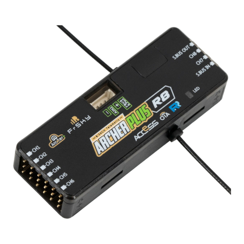
FrSky ARCHER PLUS R8 User manual

FrSky

FrSky ARCHER PLUS R8 User manual

FrSky DFT User manual

FrSky

FrSky DFT User manual

FrSky ARCHER R8 PRO User manual

FrSky

FrSky ARCHER R8 PRO User manual

FrSky D4R-II User manual

FrSky

FrSky D4R-II User manual

FrSky TW R6 User manual

FrSky

FrSky TW R6 User manual

FrSky ARCHER R8 PRO User manual

FrSky

FrSky ARCHER R8 PRO User manual

FrSky ACCESS G-RX8 User manual

FrSky

FrSky ACCESS G-RX8 User manual

FrSky ARCHER R10 PRO User manual

FrSky

FrSky ARCHER R10 PRO User manual

FrSky Delta 8 User manual

FrSky

FrSky Delta 8 User manual

FrSky Taranis X9D Plus User manual

FrSky

FrSky Taranis X9D Plus User manual

FrSky D4R-II User manual

FrSky

FrSky D4R-II User manual

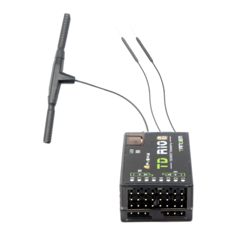
FrSky TD R10 User manual

FrSky

FrSky TD R10 User manual

FrSky ARCHER PLUS SR8 User manual

FrSky

FrSky ARCHER PLUS SR8 User manual

FrSky TD R12 User manual

FrSky

FrSky TD R12 User manual

FrSky R9 STAB OTA User manual

FrSky

FrSky R9 STAB OTA User manual

FrSky 2.4GHz ACCST R-XSR User manual

FrSky

FrSky 2.4GHz ACCST R-XSR User manual

FrSky TARANIS X9D User manual

FrSky

FrSky TARANIS X9D User manual

FrSky HORUS X10 User manual

FrSky

FrSky HORUS X10 User manual

FrSky TANDEM X20 Series User manual

FrSky

FrSky TANDEM X20 Series User manual

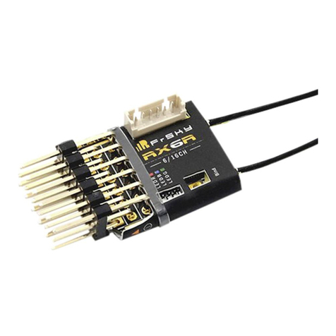
FrSky RX6R User manual

FrSky

FrSky RX6R User manual

FrSky XJT User manual

FrSky

FrSky XJT User manual

Popular Receiver manuals by other brands

Parasound AVC-1800 owner's manual

Parasound

Parasound AVC-1800 owner's manual

JVC KD-R960BTS instruction manual

JVC

JVC KD-R960BTS instruction manual

Trio JR-599 Service manual

Trio

Trio JR-599 Service manual

EchoStar DSB-880 2Ci user manual

EchoStar

EchoStar DSB-880 2Ci user manual

Blaupunkt SACRAMENTO290MC instruction manual

Blaupunkt

Blaupunkt SACRAMENTO290MC instruction manual

Arcus LRM-LR Instructions for use

Arcus

Arcus LRM-LR Instructions for use

DPCAV AV680RX quick start guide

DPCAV

DPCAV AV680RX quick start guide

Xcruiser XDSR380HD user manual

Xcruiser

Xcruiser XDSR380HD user manual

Marantz SR-5001 specification

Marantz

Marantz SR-5001 specification

Kramer 602T user manual

Kramer

Kramer 602T user manual

Sangean SR-25 brochure

Sangean

Sangean SR-25 brochure

Allo RemoteControl NICE HSRE12 instructions

Allo RemoteControl

Allo RemoteControl NICE HSRE12 instructions

Sirius Satellite Radio SRH550C user guide

Sirius Satellite Radio

Sirius Satellite Radio SRH550C user guide

Kenwood KR-V8090 Service manual

Kenwood

Kenwood KR-V8090 Service manual

HASSEB AUDIO OVER ETHERNET PRO instruction manual

HASSEB

HASSEB AUDIO OVER ETHERNET PRO instruction manual

Alpine iLX-W660E Quick reference guide

Alpine

Alpine iLX-W660E Quick reference guide

Alpine IDA-X303 - Radio / Digital Player Quick reference guide

Alpine

Alpine IDA-X303 - Radio / Digital Player Quick reference guide

Kicker KMC2 owner's manual

Kicker

Kicker KMC2 owner's manual

manuals.online logo
manuals.online logoBrands
  • About & Mission
  • Contact us
  • Privacy Policy
  • Terms and Conditions

Copyright 2025 Manuals.Online. All Rights Reserved.