AUREL XTR-8LR-USB User manual

XTR-8LR-USB
-----------------------------------------------------------------------------------------------------------------------------
----------------------
------------------
User Manual
The technical features can change without forecasting. AUR°EL S.p.A doesn’t assume any responsa ility of demage due to the improper use of the device.
-------------------------------------------------------------------------------------------------------------------------------------------------------------------
AUR°EL S.p.A.
Via Foro dei Tigli, 4 - 47015 Modigliana (FC) – ITALY
Tel.: +39.0546.941124 Fax: +39.0546.941660
Rev 1.
3
1
8
/1
1
/201
9
Page 1of 17
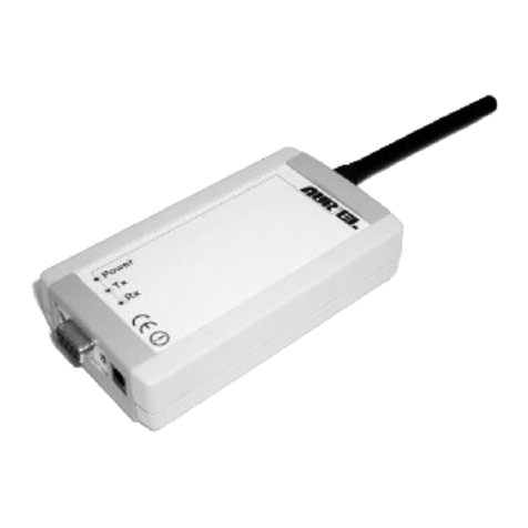
XTR-8LR-USB with external antenna
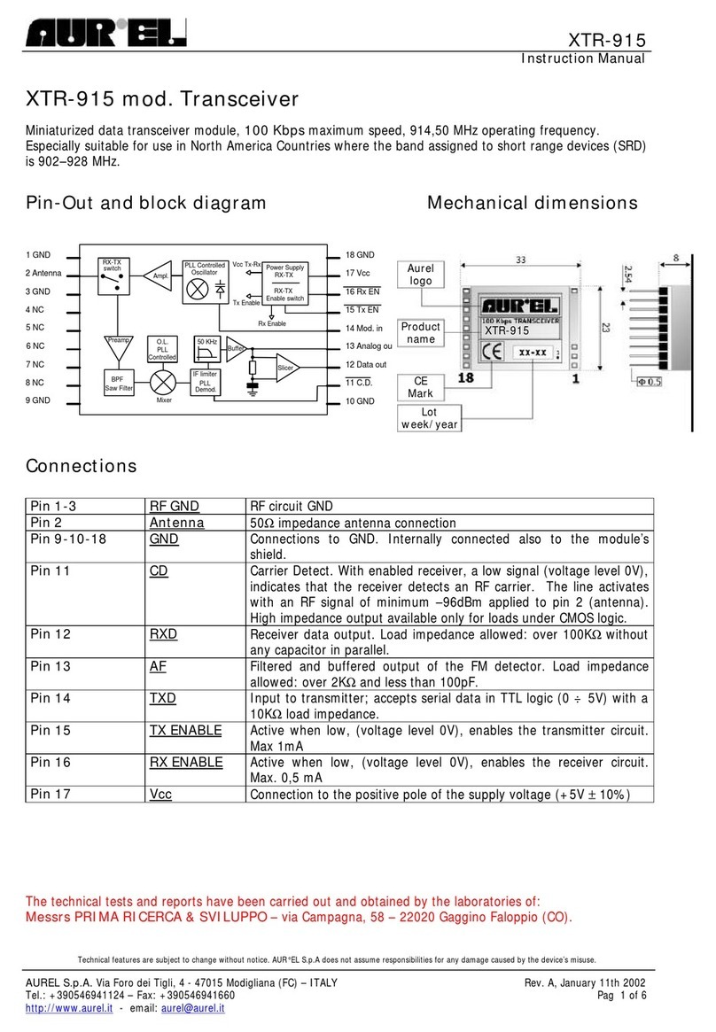
XTR-8LR-USB is an half duplex transceiver perfectly suitable for long range communication thanks to its
patented “LoRa ™” modulation technique, capable to ensure high interference immunity, very low current
consumption and high sensitivity.
Comparing this kind of modulation with the classic ones, XTR-8LR-USB has highly improved the sensitivity
of the receiver up to 20 dBm, ensuring long budget-link with output power and current consumption much
lower.
Transceiver works in 869,40÷869,65MHz (100mW, ver. 8LR100) and 868÷868,6MHz (25mW ver. 8LR10)
European bands with possibility to set the channel width .
XTR-8LR-USB is a radio-modem with Usb interface, used as receiver or data concentrator coming from
XTR-8LR10 and XTR-8LR100 modules. It can handle addressing data for point-to-multipoint or star
networks.
Main radio parameters might be set up smoothly via command mode procedure.
Operating voltage is 5V, current consumption is 20 mA in reception, 135 mA in transmission (+20dBm
ERP).
Main features
Application
Direct transmission or radiomodem mode.
No encoding or preamble is requested.
AT commands for parameters setting of internal
registers.
HyperTerminal*compatible.
Channels: 7 max.
Small form factor
( 25x70x13mm ).
UART data rate: 9600, 19200, 115200 bps.
Emitted power: max 100 mW.
Sensitivity from -118 to-144 dBm.
Operating voltage: 5V.
Standard distance: 8000 m.
Home and building automation
Irrigation control
Energy monitoring
Industrial sensors
SCADA
Alarms
Automatic Meter Reading

XTR-8LR-USB
-----------------------------------------------------------------------------------------------------------------------------
----------------------
------------------
User Manual
The technical features can change without forecasting. AUR°EL S.p.A doesn’t assume any responsa ility of demage due to the improper use of the device.
-------------------------------------------------------------------------------------------------------------------------------------------------------------------
AUR°EL S.p.A.
Via Foro dei Tigli, 4 - 47015 Modigliana (FC) – ITALY
Tel.: +39.0546.941124 Fax: +39.0546.941660
Rev 1.
3
1
8
/1
1
/201
9
Page 2of 17
Absolute maximum ratings
Operating temperature -20 °C ÷+70 °C
Storage temperature -40 °C ÷+100 °C
Supply voltage +5.5V
Input voltage -1.0 ÷Vcc + 0.3V
Output voltage -1.0 ÷Vcc + 0.3V
Technical Features:
Min. Tip. Max. Unit
DC LEVELS
Supply voltage 4.5 5.0 5.5 V
Current consumption (rx mode) 20 mA
Current consumption (tx mode @ +20 dBm) 90 135 150 mA
Current consumption (command mode) 24 mA
RF TX
Band 869.4÷869.65 MHz
Emitted power 5 10 20 dBm
Modulation LORA™
Channel width -3dB 20.8 KHz
Channel width -3dB 62.5 KHz
Channel width -3dB 125 KHz
Channel width -3dB 250 KHz
Spurious emissions < 1GHz -36 dBm
Spurious emissions > 1GHz -30 dBm
Power on adjacent channel in TX (note 2) 50 nW
ESD protection antenna (61000-4-2) 8 KV
RF RX
Sensitivity in RX, 250KHz band (SF:6-10-12) -115 -129 -134 dBm
Sensitivity in RX, 125KHz band (SF:6-10-12) -118 -132 -137 dBm
Sensitivity in RX, 62.5KHz band (SF:6-10-12) -121 -135 -140 dBm
Sensitivity in RX, 20.8KHz band (SF:6-10-12) -127 -140 -144 dBm
RF band 6 MHz
Adjacent channel selectivity ( note 3 ) 50 dB
Adjacent channel saturation ( note 4 ) ≥87 dB
Blocking test at ±2MHz ( note 5 ) 85 90 dB
Blocking test at ±10MHz ( note 5 ) 85 94 dB
Performance
Spreading Factor 6 10 12
Coding Rate 4/5 4/8
Serial Bit Rate (note 1) 9600 19200 115200 bps
Package size 1 248 Byte
Outdoor range 8000 m
Channels 1 7 n°
Channel space with 20,8KHz BW 25 kHz
Timing

XTR-8LR-USB
-----------------------------------------------------------------------------------------------------------------------------
----------------------
------------------
User Manual
The technical features can change without forecasting. AUR°EL S.p.A doesn’t assume any responsa ility of demage due to the improper use of the device.
-------------------------------------------------------------------------------------------------------------------------------------------------------------------
AUR°EL S.p.A.
Via Foro dei Tigli, 4 - 47015 Modigliana (FC) – ITALY
Tel.: +39.0546.941124 Fax: +39.0546.941660
Rev 1.
3
1
8
/1
1
/201
9
Page 3of 17
PWRDN
→
RX_NORMAL 1.5 ms
RX_NORMAL
→
PWRDN 1.5 ms
TX_NORMAL
→
RX_NORMAL See : EQ1, EQ2 , EQ3, Picture 4
RX NORMAL
→
TX_NORMAL See : EQ1, EQ2 , EQ3, Picture 4
Default Settings
Channel (CN2) 869.5 MHz
Emitted power (tx) 20 dBm
Serial Bit Rate (only for data) note1 115200 Bps
Bandwidth 62.5 KHz
Spreading Factor 8 SF
Note l: UART data is meant 8,n,1. UART Speed (command S8) is related to data comunication. For command mode communication
this set up has no effect and it works basically to 9600bps
Note2: Test carried out according to method described in ETSI EN 300 220-1 V2.4.1 paragraph 7.6
Note3: Test carried out according to method described in ETSI EN 300 220-1 V2.4.1 paragraph 8.3
Note4: Test carried out according to method described in ETSI EN 300 220-1 V2.4.1 paragraph 8.3.4
Note5: Test carried out according to method described in ETSI EN 300 220-1 V2.4.1 paragraph 8.4
Description
Picture 1: XTR-8LR-USB
Normal mode in Rx: indicated through a red led blinking.
Command Mode: indicated through a fixed red light led.
Valid data reception: Blue Light Led blinking.
Data Transmission: Fixed Green light led for the whole transmission.
LoRa modulation:
The RF modulator and demodulator use the spread spectrum radio technique and it's possible to set
Chip/Symbol ratio from 128 to 4096, depending on the desired RF sensitivity and flying time.
Improvement of sensitivity is outstanding compared to standard FSK modulation technique: 7,5 dB with 128
Chip/Symbol value and 20 dB with 4096 Chip/Symbol value.
Furthermore it is granted a general improvement of interference immunity, adjacent channel immunity and
blocking tests compared to FSK demodulator.
The tables here below show how to properly set modulation parameters depending on sensitivity and flying
time desired.
For a better clarification, flying time identifies the radio channel occupation for a data package composed of
8 bytes preamble + 8 bytes payload + CRC.

XTR-8LR-USB
-----------------------------------------------------------------------------------------------------------------------------
----------------------
------------------
User Manual
The technical features can change without forecasting. AUR°EL S.p.A doesn’t assume any responsa ility of demage due to the improper use of the device.
-------------------------------------------------------------------------------------------------------------------------------------------------------------------
AUR°EL S.p.A.
Via Foro dei Tigli, 4 - 47015 Modigliana (FC) – ITALY
Tel.: +39.0546.941124 Fax: +39.0546.941660
Rev 1.
3
1
8
/1
1
/201
9
Page 4of 17
Bandwidth 250KHz
Spreading Factor Sensitivity (dBm) Flying Time (ms)
6 -115 10
7 -120 21
8 -123 41
9 -126 72
10 -129 144
11 -131 248
12 -134 496
Bandwidth 125KHz
Spreading Factor Sensitivity (dBm) Flying Time (ms)
6 -118 20
7 -123 41
8 -126 82
9 -129 144
10 -131 287
11 -134 495
12 -137 990
Bandwidth 62,5KHz
Spreading Factor Sensitivity (dBm) Flying Time (ms)
6 -121 41
7 -126 82
8 -129 164
9 -132 288
10 -135 577
11 -137 990
12 -140 1980
Bandwidth 20,8KHz
Spreading Factor Sensitivity (dBm) Flying Time (ms)
6 -127 124
7 -130 246
8 -134 492
9 -137 862
10 -140 1730
11 -142 2960
12 -145 5940

XTR-8LR-USB
-----------------------------------------------------------------------------------------------------------------------------
----------------------
------------------
User Manual
The technical features can change without forecasting. AUR°EL S.p.A doesn’t assume any responsa ility of demage due to the improper use of the device.
-------------------------------------------------------------------------------------------------------------------------------------------------------------------
AUR°EL S.p.A.
Via Foro dei Tigli, 4 - 47015 Modigliana (FC) – ITALY
Tel.: +39.0546.941124 Fax: +39.0546.941660
Rev 1.
3
1
8
/1
1
/201
9
Page 5of 17
Above Charts show increased sensitivities for increased SF values; decreased data rate for increased SF and
decreased Bandwidths.
The parameters choice have to be made by assessing at first, the bandwidth: if more channels are requested
it's mandatory to choose 20,8 KHz BW, otherwise, 62,5 or 125 KHz BW.
In this case SF value equals to 8-10 is the best trade-off between RF sensitivity and flying time.
Very often in radio control applications, payload is not more than 8-10 bytes and 0,5 sec is a reasonable time
for transmission and feedback (ACK) reception.
Here below the calculation equations of flight times for packet radio with payloads greater than 8Bytes:
EQ1
Tsym: Time symbol
SF: Spreading Factor from 6 to 12
BW: Bandwidth in Hz (S2 Register)
EQ2
PayloadsymbNb: Payload symbol quantity
nBytePL: Payload byte quantity
CR: coding rate from 1 to 4 (register S6)
EQ3
Tpachet: data packet total timing in seconds
12,25: Symbols quantity used on preamble
From Aurel website you can download an Excel spreadsheet that automatically calculates the flight
time radio according to selected parameters.
Data packet frame:
XTR-8LR100 is a radio modem working in packet mode and handling addresses for point-to-multipoint
networks.
Packet has a 255 bytes max length, where 247 bytes are the payload and 7 the addresses.
It's made up of:
•Preamble: it comprises 8 bytes of variable length depending on data rate, used for synchronization
purposes..
•Header: it comprises information related to the payload lengths, Code Rate, and CRC presence of
payload 16 bit
•Network_ID: every module has got a 4 bytes network ID, editable via AT command. (It’s present
only in net modality S10=1)
=BW
Tsym
SF
2
(
)
(
)
( ) ( )
+×
−× +×−×
+= 4
24
4448
8CR
SF
SFnBytePL
ceilingbNbPayloadsym
(
)
TsymbNbPayloadsymTpachet ×+= 25,12

XTR-8LR-USB
-----------------------------------------------------------------------------------------------------------------------------
----------------------
------------------
User Manual
The technical features can change without forecasting. AUR°EL S.p.A doesn’t assume any responsa ility of demage due to the improper use of the device.
-------------------------------------------------------------------------------------------------------------------------------------------------------------------
AUR°EL S.p.A.
Via Foro dei Tigli, 4 - 47015 Modigliana (FC) – ITALY
Tel.: +39.0546.941124 Fax: +39.0546.941660
Rev 1.
3
1
8
/1
1
/201
9
Page 6of 17
•Source Address: Module or Node address from which the data packet starts (sender), composed by 2
bytes for a maximum node capability of 65536 nodes each network editable via AT command. (It’s
present only in net modality S10=1)
•Destination Address: 2 bytes destination node address. This address can be changed via AT
command. It must be forwarded on serial port before the payload.
•0xFF (default) address means a broadcasting message: in this case every node joining the network
(same network_ID) receives the message (It’s present only in net modality S10=1)
•Payload: from 1 to 247 bytes. When received, the message is forwarded to UART output only in case
Network_ID and Destination address are corresponding, otherwise it's eliminated. In case of
transmission, data coming from UART port are included in payload field.
•Payload CRC: checksum 2 Bytes
In normal TX and RX operations, it is mandatory to set up the 2 needed addresses for network functionality
in command mode, then move to NORMAL mode and send/receive data (payload) via UART port. To
transmit a radio data packet, User must sent on UART the Destination address before the payload. Data are
not yet encryped.
Picture 2: Data radio packet frame in NORMAL Mode with addressing
In NORMAL mode no network (register S10=0) fields NETWORK ID, SOURCE ID e DESTINATION
ADDRESS will not present on radio protocol and 255 bytes payload will be at disposal
Picture 3: Data radio packet frame in NORMAL Mode no network
Note:
By selecting spreading factor 6, the Header field is excluded. The payload must be length 15
Byte. This method is expected to LORA modulation in order to limit flight time and duty-cycle
transmission .
Payload of different length of 15 Byte, will be transmitted but rejected by the receiving unit.
Installing procedure and use
To start using the XTR-8LR-USB, proceed as follows:

XTR-8LR-USB
-----------------------------------------------------------------------------------------------------------------------------
----------------------
------------------
User Manual
The technical features can change without forecasting. AUR°EL S.p.A doesn’t assume any responsa ility of demage due to the improper use of the device.
-------------------------------------------------------------------------------------------------------------------------------------------------------------------
AUR°EL S.p.A.
Via Foro dei Tigli, 4 - 47015 Modigliana (FC) – ITALY
Tel.: +39.0546.941124 Fax: +39.0546.941660
Rev 1.
3
1
8
/1
1
/201
9
Page 7of 17
1. Install computer drivers for the USB port, for this purpose use the following link
http://www.ftdichip.com/Drivers/D2XX.htm
taking care to identify the appropriate driver for your
operating system from the PC.
2.
Connect the
XTR-8LR-USB
to the PC's USB port: the computer should report the detection of
USB and communicate the outcome of the installation of the drivers and the COM number in
use. If this were not reported, so it is advisable to open the Windows page about managing
devices, click on the "Port (COM menu and LPT)", right-click on the installed USB ports, and
the properties of each of them, seek COM associated with the FTDI driver.

XTR-8LR-USB
-----------------------------------------------------------------------------------------------------------------------------
----------------------
------------------
User Manual
The technical features can change without forecasting. AUR°EL S.p.A doesn’t assume any responsa ility of demage due to the improper use of the device.
-------------------------------------------------------------------------------------------------------------------------------------------------------------------
AUR°EL S.p.A.
Via Foro dei Tigli, 4 - 47015 Modigliana (FC) – ITALY
Tel.: +39.0546.941124 Fax: +39.0546.941660
Rev 1.
3
1
8
/1
1
/201
9
Page 8of 17
3. Open a communications software to serial ports, we recommended to use RealTerm free download on
the following link: http://sourceforge.net/projects/realterm/files/Realterm/
All the examples cited in this manual have been performed with Realterm.
Many communication programs are available for serial ports suitable for this purpose, however, in
order to exclude errors introduced by them and to get adequate support from the vendor, it is
recommended to perform the experiments described below using Realterm, at least until it reaches an
appropriate level of confidence with the XTR-8LR100 form or XTR-8LR10.
4. Start the program and set the communication parameters as shown below.
Communication speed 115200 bps, the START bit, 8 data bits, and a STOP bit, no parity. Select the
port number that has been associated with XTR-8LR-USB, in this case the port associated with the
XTR-8LR-USB is the "Port 109".
After each change of the working parameters of the serial port, remember to press the button "Change"
to Realterm, the set values are visible at any time in the small box at the bottom right of the screen
Realterm.

XTR-8LR-USB
-----------------------------------------------------------------------------------------------------------------------------
----------------------
------------------
User Manual
The technical features can change without forecasting. AUR°EL S.p.A doesn’t assume any responsa ility of demage due to the improper use of the device.
-------------------------------------------------------------------------------------------------------------------------------------------------------------------
AUR°EL S.p.A.
Via Foro dei Tigli, 4 - 47015 Modigliana (FC) – ITALY
Tel.: +39.0546.941124 Fax: +39.0546.941660
Rev 1.
3
1
8
/1
1
/201
9
Page 9of 17
5. Click on the menu Send, and select CR and LF, then insert on the blank window "+++" and press
"Send ASCII." If communication is successful, you will receive an answer as the following screen,
and the RED LED will be lit:
6. By now, you can send AT commands to the XTR-8LR-USB.
Send ATS90 command as below, you will receive as a response status of all setting records, with the
exception of ATS0 register (hardware and firmware).

XTR-8LR-USB
-----------------------------------------------------------------------------------------------------------------------------
----------------------
------------------
User Manual
The technical features can change without forecasting. AUR°EL S.p.A doesn’t assume any responsa ility of demage due to the improper use of the device.
-------------------------------------------------------------------------------------------------------------------------------------------------------------------
AUR°EL S.p.A.
Via Foro dei Tigli, 4 - 47015 Modigliana (FC) – ITALY
Tel.: +39.0546.941124 Fax: +39.0546.941660
Rev 1.
3
1
8
/1
1
/201
9
Page 10 of 17
If never used it shall respond with the default settings tab.
7. Change the desired parameters, type the ATCC command to exit the state of the Command Mode, or
ATWR to save the new parameters on EEPROM and exit the command mode, as a confirmation of the
command, the XTR-8LR-USB will respond with OK EXIT and red LED turns off (see below).
Once out of the Command Mode will recover in Normal receive mode (Blink RED LED every 3
seconds)

XTR-8LR-USB
-----------------------------------------------------------------------------------------------------------------------------
----------------------
------------------
User Manual
The technical features can change without forecasting. AUR°EL S.p.A doesn’t assume any responsa ility of demage due to the improper use of the device.
-------------------------------------------------------------------------------------------------------------------------------------------------------------------
AUR°EL S.p.A.
Via Foro dei Tigli, 4 - 47015 Modigliana (FC) – ITALY
Tel.: +39.0546.941124 Fax: +39.0546.941660
Rev 1.
3
1
8
/1
1
/201
9
Page 11 of 17
Operation modes:
Device works in 2 states operation modes:
1. COMMAND MODE
2. NORMAL MODE
1. Command Mode
Command mode allows the user to set up operating parameters.
Configuration occurs via AT commands sent to RealTerm software or a dedicated PC interface.
“Command Mode” status allows to the user to configure the working parameters of the device.
Programmation is carried out from AT commands sent through Real Term or a dedicated PC interface.
Set the communication with the usb serial port, Realterm or other similar, with the following parametes:
Data rate 115200, one Start bit, 8 data bit and one Stop bit, no parity, select CR and LF.
Note: in Command-Mode insert CR ( carriage return ) and LF (Line Feed) as termination command.
COMMAND-MODE escape
After 2 minute from last command sent, module comes back to receiver mode. Otherwise, in order to force
the exit, send ATCC command: if everything is right you'll get a OK EXIT as confirmation and the red led
light switches off. All modifications became effective only after the Command-Mode Escape.
AT commands list:
Possible commands sent to the module are referred to the reading and writing of registers containing settings
of the device functionality.
Configuration registers reading and writing occurs by sending the sequence AT followed by command or
register name, according to the standard of PSTN modems.
Here below you find the list of available commands: in order to use them, please abide by the examples of
registers reading and writing shown in next page. The writing and reading of registers and the commands
sent to the module are carried out with sequence AT before the command or register name (AT stands for
attention), as the standard used in the PSTN modem.
Here below you find the list of available commands: in order to use them, please abide by the examples of
registers reading and writing shown in next page. The writing or reading of registers not included in the chart
will return the reply NO ACCESS.
AT COMMAND <CR> <LF>
Uppercase characters that come
before a command or a register
Commands are codes
including one or more
characters
Command ends always with <CR>
Carriage Return <LF> line feed
Register
Name Function Values
S0
r
VER. HW/FW
It mean the radio module version
HW and FW
Byte High =
Hw Version
(modello/HW)
Byte Low = Ver. firmware

XTR-8LR-USB
-----------------------------------------------------------------------------------------------------------------------------
----------------------
------------------
User Manual
The technical features can change without forecasting. AUR°EL S.p.A doesn’t assume any responsa ility of demage due to the improper use of the device.
-------------------------------------------------------------------------------------------------------------------------------------------------------------------
AUR°EL S.p.A.
Via Foro dei Tigli, 4 - 47015 Modigliana (FC) – ITALY
Tel.: +39.0546.941124 Fax: +39.0546.941660
Rev 1.
3
1
8
/1
1
/201
9
Page 12 of 17
S1
r/w
BANDA
Operating band frequency
0=
868,00 – 868,60 MHz (NI,
disponibile per altre versioni)
1=
869,40 – 869,65 MHz (default)
S2
r/w
BANDWIDTH
RF channel bandwidth
0 =
20,8 KHz
1 = 62,5 KHz (default)
2 = 125 KHz
3 = 250 KHz
S3
r/w
(nota 2)
CANALE
Operating radio channel
To apply with limits imposed by EN300 220
normative, channeling is viable only with
BW 20,8 KHz; for the others BW (62,5 KHz
e 125 KHz) setting of channel is useless and
module will work only on default channel
0
= 869,45MHz
1
= 869,475MHz
2
= 869,5MHz
(default)
3
= 869,525MHz
4
= 869,55MHz
5
= 869,575MHz
6
= 869,6MHz
7
= 868,3MHz
8
= 869,850MHz
S4
r/w
RF POWER
RF power emitted in antenna
0 =
+5dBm
1 = +10dBm
2 = +20dBm (default)
S5
r/w
SPREADING
FACTOR
Spreading factor
6
= 64 (chip/symbol)
7= 128
8 = 256 (default)
9= 512
10 = 1024
11 = 2048
12 = 4096
S6
r/w
ERROR
CODING
Error recovery
1
=
4/5 (default)
2 =4/6
3 =4/7
4 =4/8
S7
r/w
RSSI
ENABLE
Adds in rear of payload the RRSI
value (2 bytes)
0
=
No RSSI (default)
1 =RSSI in coda al payload
S8
r/w
(nota 3)
UART BPS
UART data rate
0
= 9.600 bps
1= 19.200 bps
2= 115.200 bps (default)
S10
r/w
NETWORK
ENABLE
Adds on top of payload, the ID
network and Source address
0
=
No Rete (default)
1 =Rete
S11
r/w
NETWORK
ID
It sets the device network address ( 4
byte hex )
Min
= 00000001 (default)
Max = FFFFFFFF
S12
r/w
SOURCE
ADDRESS
It sets the device ID or sender (2
bytes)start address message
Min
= 0001 (default)
Max = FFFF (broadcast)

XTR-8LR-USB
-----------------------------------------------------------------------------------------------------------------------------
----------------------
------------------
User Manual
The technical features can change without forecasting. AUR°EL S.p.A doesn’t assume any responsa ility of demage due to the improper use of the device.
-------------------------------------------------------------------------------------------------------------------------------------------------------------------
AUR°EL S.p.A.
Via Foro dei Tigli, 4 - 47015 Modigliana (FC) – ITALY
Tel.: +39.0546.941124 Fax: +39.0546.941660
Rev 1.
3
1
8
/1
1
/201
9
Page 13 of 17
S90
r
REGISTERS
STATUS
Registers value restores
S1
= x (x = returned value)
S2 = x
S3 = x
….
Sn = x
S91
r/w
DEFAULT
VALUES
Setted at 1 it stores on register, the
default values
Impostato a “1” reimposta i valori di
default.
Se un registro è modificato,
restituisce il valore “0”, cioè registri
differenti da default.
0
= Modified values (r)
1= Default values (r/w)
(note 1) NI means not implemented yet. Command execution doesn't have any effect
(note 2) To apply with limits imposed by EN300 220 normative, channeling is viable only with BW 20,8 KHz; for the others BW
(62,5 KHz e 125 KHz) setting of channel is useless and module will work only on default channel.
(note 3) UART data rate setting (command S8), refers exclusively to data communication. In command mode this setting has no
effect and it will work onlt at 9600 bps.
Command Name Function
WR WRITE
Write registers value to EEPROM
CC COMMAND
CLOSE
Command Mode exit
Sx NOME
REGISTRO
Register ID to be read or write
Tab. 2: commands
Return values to commands and operations on registers
Positive return: OK<CR><LF>
Negative return: <bl> ERROR<CR><LF>
Forbidden operation: <bl> NO ACCESS<CR><LF>
Command mode exit EXIT<CR><LF>
<CR> Carriage Return, ASCII character 13; <LF> Line Feed, ASCII character 10; <bl> ASCII character 32.

XTR-8LR-USB
-----------------------------------------------------------------------------------------------------------------------------
----------------------
------------------
User Manual
The technical features can change without forecasting. AUR°EL S.p.A doesn’t assume any responsa ility of demage due to the improper use of the device.
-------------------------------------------------------------------------------------------------------------------------------------------------------------------
AUR°EL S.p.A.
Via Foro dei Tigli, 4 - 47015 Modigliana (FC) – ITALY
Tel.: +39.0546.941124 Fax: +39.0546.941660
Rev 1.
3
1
8
/1
1
/201
9
Page 14 of 17
Readout of a register
Syntax: ATSx<CR><LF> [x = 1, ...,16 register to be read]
Return : value stored in the register if the command sintax is correct followed by <CR><LF>.
Register value is given digit after digit as ASCII characters.
Example: ‘16’ is given as the sequence of ASCII characters 0x31,0x36, corresponding to digit ‘1’ and ‘6’.
Same procedure must be applied in case of writing a new value in a register.
Writing of a register
Syntax: ATSx=Y<CR><LF> [x = 2, 3, 4 register to write on, y = value to add]
Return: as described in 'Return values'
All values stored in the registers will be lost when the module is turned off, unless the changes are saved in
microcontroller EEPROM memory by means of the specific command ATWR: in this case the saved values
will be active even if the module is turned off and then on.
Command to save registers value in EEPROM
Syntax: ATWR<CR><LF>
Return: as described in 'Return values'
Command to quit command mode
Syntax: ATCC<CR><LF>
Return: as described in 'Return values'
Command mode exit occurs, even without ATCC command, automatically after 10 sec. of idle state, or after
the command ATWR.
3. NORMAL
Enabled once the XTR-8LR-USB is inserted in a PC USB port and also once it comes back from
“Command Mode”. Normal mode is shown by the red led blinking each three seconds. The device is able to
receive data thought RF and through Usb and forward consequently. The device is always in reception and it
enters in transmission once it receives data though Usb.
The way the store & Forward mechanism works is described by couples of sequence operations:
Store from UART on unit A /Forward to RF buffer on unit A/ RF TX unit A
RF RX unit B/Forward to UART output on unit B [Picture 4]

XTR-8LR-USB
-----------------------------------------------------------------------------------------------------------------------------
----------------------
------------------
User Manual
The technical features can change without forecasting. AUR°EL S.p.A doesn’t assume any responsa ility of demage due to the improper use of the device.
-------------------------------------------------------------------------------------------------------------------------------------------------------------------
AUR°EL S.p.A.
Via Foro dei Tigli, 4 - 47015 Modigliana (FC) – ITALY
Tel.: +39.0546.941124 Fax: +39.0546.941660
Rev 1.
3
1
8
/1
1
/201
9
Page 15 of 17
The absence of data towards the usb is given by a Timeout ( equal to the 2 serial byte time based on the data
rate ); expired it the transceiver does not memorize other data in input until the whole data forwarding inside
the radio buffer.
Max packet size is 247 bytes ( S10=1 register ) in the addressing NORMAL modality and 255 byte ( S10=0
register ) in the not addressing NORMAL modality.
Data are sent on air only when the UART storage phase is over. Microcontroller checks the incoming
packets from radio receiver and enables forwarding to UART output port only in case of valid packets
(corrupted packets are eliminated).
RTS line is helpful to monitor UART buffer status: it's normally low level and goes high when buffer is full
or during emptying of UART buffer towards radio buffer, or when data are sent on TX_UART.
In order to grant a proper functionality of the transceiver, it's not allowed to overlap phases: i.e. if unit
is emptying UART buffer to radio buffer, any data incoming from USB port are lost.
Likewise is not allowed to receive data from RF until the previous packet is still to be transmitted
through USB port.
Furthermore consider that USB reception has priority over radio reception : when a byte is received
from USB the radio reception in stopped and the device waits until the USB packet is completed.
Therefore in that phase eventually radio data are lost.
In order to execute properly the exchange of packet from/to UART port, it's recommended to control
the RTS line as go/stop operation signal.
Using the NORMAL mode with addressing:
NORMAL mode allows to work with addressing data packet, so a potential network composed by many
devices permit a point-to-point communication, or point-multipoint.
From command-mode network function is achievable with ATS10=1 resigter, other registers to be setted are
NETWORK ID reg.number S11 and SOURCE ADDRESS S12 (2 bytes) a unique identifier for each device.
A wireless network could be composed by 2 to 65536 devices. SOURCE ADDRESS identifies from which
device the message starts, DESTINATION ADDRESS identifies who is the device to which the message is
meant. From this condition the device forwards on UART the radio data packet received, but only those who
have the same NETWORK ID and DESTINATION ADDRESS. When the device transmit the
DESTINATION ADDRESS must be applied ever before the payload.
In case of point –multipont network, it’s necessary to set up the DESTINATION ADDRESS on FFFF, then
all the related devices with same NETWORK ID will receive the payload preceded by 0xFFFF.
No automatic messages ACK is provided.

XTR-8LR-USB
-----------------------------------------------------------------------------------------------------------------------------
----------------------
------------------
User Manual
The technical features can change without forecasting. AUR°EL S.p.A doesn’t assume any responsa ility of demage due to the improper use of the device.
-------------------------------------------------------------------------------------------------------------------------------------------------------------------
AUR°EL S.p.A.
Via Foro dei Tigli, 4 - 47015 Modigliana (FC) – ITALY
Tel.: +39.0546.941124 Fax: +39.0546.941660
Rev 1.
3
1
8
/1
1
/201
9
Page 16 of 17
As an example here below a communication between device 1 and 2 on network A for a message
“provalink”
Figura 5:Diagramma di trasmissione ricezione del messaggio “provalink” dal nodo 1 al nodo 2.
Hereinafter are described necessary operations to realize the example on picture 5
From command-mode of device 1, send the following AT command string:
Commands Answer Note
+++<CR><LF> OK<CR><LF> Command-mode enters
ATS10=1<CR><LF> OK<CR><LF> Network mode activates
ATS11=0000000A<CR><LF> OK<CR><LF> Assigns network address “A”
ATS12=0001<CR><LF> OK<CR><LF> Assigns device address “1”
ATWR<CR><LF> OK<CR><LF> Save and exit
Node 1 has been set in NORMAL Mode with addressing, NETWORK ID = A and SOURCE ADDRESS =
1. ATWR stores new settings on EEprom and brings back the device on SLEEP
From command-mode of device 2, send the following AT command string:
Commands Answer Note
+++<CR><LF> OK<CR><LF> Command-mode enters
ATS10=1<CR><LF> OK<CR><LF> Network mode activates
ATS11=0000000A<CR><LF> OK<CR><LF> Assigns network address “A”
ATS12=0002<CR><LF> OK<CR><LF> Assigns device address “2”
ATWR<CR><LF> OK<CR><LF> Save and exit
As per node 1 Commands string is repeated excluding command ATS12 that assigns device address
SORUCE ADDRESS = 2
Modalità NORMAL su entrambi i dispositivi e inoltrare sulla Usb del dispositivo “1” la sequenza “\x0 \x2
provalink” (¹).
Device 1 sends the message via radio.
From all devices in reception (potentially more than 65000), only the device called “2” will forward on its
own TX_UART line “01provalink” message.
Same as mentioned in the above example, addressing method is obtained placing ahead to the payload, in
this case “provalink” the receiver address. Listening device “2” will receive the payload preceded by the
sender address “\x0 \x1 provalink” (¹).
Step 1 – from Usb to
XTR-8LR-USB
Address: 0x0002
Payload:
provalink
Step 3 - from
XTR-8LR-USB to
Usb
Address: 0x0001
Payload: provalink
Step 2
–
RF Transmission
Node
0x0001
Dongle
Node
0x0002
Dongle

XTR-8LR-USB
-----------------------------------------------------------------------------------------------------------------------------
----------------------
------------------
User Manual
The technical features can change without forecasting. AUR°EL S.p.A doesn’t assume any responsa ility of demage due to the improper use of the device.
-------------------------------------------------------------------------------------------------------------------------------------------------------------------
AUR°EL S.p.A.
Via Foro dei Tigli, 4 - 47015 Modigliana (FC) – ITALY
Tel.: +39.0546.941124 Fax: +39.0546.941660
Rev 1.
3
1
8
/1
1
/201
9
Page 17 of 17
(¹):
Correct syntax to PC realterm terminal. Network address is write in “hex” and “provalink” message in ASCII. Different
programs used from Realterm could require different syntax. For more information related to Realterm using please look at the
DEMO BOARD_XTR_8LR100 user manual
Antenna:
The device has a SMA connector for having an external antenna.
Reference Rules
XTR-8LR-USB transceiver is compliant with the European set of rules EN 300 22-2 and EN 301 489-3.
Tests has been performed through transmissions of Pseudo Code Random at 500bps(CEPT 70-03). The
occupancy of bandwidth has been performed through transmissions of Pseudo Code Random at 500bps. In
addition, the product has been tested according to EN 60950.
This device is compliant with EN 62479, connected to the electromagnetic field human exposition, if used
with temporal duty cycle not higher than 10% like foreseen in CEPT 70-03 recommendation.
CEPT 70-03
XTR-8LR-USB transceiver operates in a harmonized frequency band and therefore, in order to comply with
local regulations, the device must be used on the time scale with maximum duty-cycle time 10% (equivalent
to 6 to 60 minutes of usage ).
Version:
DATE Revision Firmware
Main variation concerning the previous version
1.0 0112 First Release
15/05/2016 1.1 0112 Introduced part related to installing USB driver
17/10/2016 1.2 0112 Update photos and product name, LoRa ™
Included Note about SF6 on page 7
18/11/2019 1.3 0114 Various fixes
Table of contents
Other AUREL Transceiver manuals
Popular Transceiver manuals by other brands
Radio Shack
Radio Shack BTX-128 owner's manual
GarrettCom
GarrettCom Magnum TP1 Installation & user guide
Comnet
Comnet FDX72 1 Series Installation and operation manual

Team Electronic
Team Electronic TeCom PS 16K PMR446 manual

TEKMAX TELECOM
TEKMAX TELECOM TR-450H user manual
Standard Horizon
Standard Horizon HX370E owner's manual
