Icom IC-M506 User manual

INSTRUCTION MANUAL
iM506EURO
VHF MARINE TRANSCEIVERS
iM506

i
PREFACE
Thank you for choosing this Icom product.
This product is designed and built with Icom’s state of the art
technology and craftsmanship. With proper care, this product
should provide you with years of trouble-free operation.
We appreciate you making the IC-M506/IC-M506EURO your
transceiver of choice, and hope you agree with Icom’s philos-
ophy of “technology first.” Many hours of research and devel-
opment went into the design of your IC-M506/IC-M506EURO.
DFEATURES
❍Integrated AIS Receiver *
❍NMEA 2000™ Connectivity *
❍2 minutes Last Call Voice Recording
❍Superb Active Noise Cancelling
*Depends on transceiver version.
IMPORTANT
READ ALL INSTRUCTIONS carefully and completely
before using the transceiver.
SAVE THIS INSTRUCTION MANUAL — This in-
struction manual contains important operating instructions
for the IC-M506/IC-M506EURO.
EXPLICIT DEFINITIONS
WORD DEFINITION
RWARNING! Personal injury, fire hazard or electric
shock may occur.
CAUTION Equipment damage may occur.
NOTE
If disregarded, inconvenience only. No risk
of personal injury, fire or electric shock.
CLEAN THE TRANSCEIVER AND MICROPHONE THOR-
OUGHLY WITH FRESH WATER after exposure to water
including salt, otherwise, the keys and switch may become
inoperable due to salt crystallization.
Icom is not responsible for the destruction or damage to the
Icom transceiver, if the malfunction is because of:
• Force majeure, including, but not limited to, fires, earthquakes,
storms, floods, lightning, other natural disasters, disturbances,
riots, war, or radioactive contamination.
• The use of Icom transceivers with any equipment that is not
manufactured or approved by Icom.

IN CASE OF EMERGENCY
If your vessel requires assistance, contact other vessels and
the Coast Guard by sending a Distress call on Channel 16.
Or, transmit your Distress call using digital selective calling
on Channel 70.
INSTALLATION NOTE
Installation:
The installation of this equipment should be made in such a
manner as to respect the EC recommended electromagnetic
field exposure limits. (1999/519/EC)
The maximum RF power available from this device is 25
watts. The antenna should be installed as high as possible
for maximum efficiency and the installation height should be
at least 1.4 meters above any accessible position. In the case
where an antenna cannot be installed at a reasonable height,
then the transmitter should neither be continuously operated
for long periods if any person is within a distance of 1.4 me-
ters of the antenna, nor operated at all if any person is touch-
ing the antenna.
It is recommended that antenna of a maximum gain of 3 dB
are used. If higher gain antenna are required then please
contact your Icom distributor for revised installation recom-
mendations.
Operation:
The exposure to RF electromagnetic field is only applicable
when this device is transmitting. This exposure is naturally
reduced due to the nature of alternating periods of receiving
and transmitting. Keep your transmissions to the minimum
necessary.
USING CHANNEL 16
DISTRESS CALL PROCEDURE
1. “MAYDAY MAYDAY MAYDAY.”
2. “THIS IS ...............” (name of vessel).
3. Say your call sign or other description of the vessel (AND
9 digit DSC ID if you have one).
4. “LOCATED AT ...............” (your position).
5. State the nature of the distress and assistance required.
6. Give any other information which might facilitate the res-
cue.
USING DIGITAL SELECTIVE CALLING (Ch 70)
DISTRESS CALL PROCEDURE
1. While lifting up the key cover, hold down [DISTRESS]
for 3 seconds until you hear 3 short beeps and then one
long beep.
2. Wait for an acknowledgment on Channel 70 from a coast
station.
• After the acknowledgement is received, Channel 16 is auto-
matically selected.
3. Hold down [PTT], then transmit the appropriate informa-
tion as listed to the left.
ii

iii
PRECAUTIONS
RWARNING! NEVER
connect the transceiver to an AC
outlet. This could cause a fire, electric shock and damage the
transceiver.
RWARNING! NEVER connect the transceiver to a pow-
er source of more than 16 V DC, such as a 24 V battery. This
could cause a fire and damage the transceiver.
RWARNING! NEVER reverse the DC power cable po-
larity when connecting to a power source. This could cause a
fire, electric shock and damage the transceiver.
RWARNING! NEVER remove the fuse holders on the
DC cable. This could cause a fire, electric shock and damage
the transceiver.
RWARNING! NEVER operate the transceiver during a
lightning storm. It may result in an electric shock, cause a
fire or damage the transceiver. Always disconnect the power
source and antenna before a storm.
CAUTION:
NEVER
place the transceiver where normal
operation of the vessel may be hindered or where it could
cause bodily injury.
KEEP the transceiver and microphone at least 1 m away
from the vessel’s magnetic navigation compass.
DO NOT place or leave the transceiver in areas with tem-
peratures below –20°C or above +60°C or, in areas subject to
intense sunlight, such as the dashboard.
DO NOT use harsh solvents such as benzine or alcohol to
clean the transceiver, as they will damage the transceiver’s
surfaces. If the transceiver becomes dusty or dirty, wipe it
clean with a soft, dry cloth.
DO NOT disassemble or modify the transceiver for any rea-
son.
BE CAREFUL! The transceiver rear panel will become
hot when operating continuously for long periods of time.
Place the transceiver in a secure place to avoid inadvertent
use by children.
BE CAREFUL! The transceiver meet IPX8 requirements
and the optional HM-195 commandmicIV™meet IPX7 re-
quirements for waterproof protection. However, once the
transceiver has been dropped, waterproof protection cannot
be guaranteed because of possible damage to the transceiv-
er’s case or the waterproof seal.
* Except for the DC power connector, NMEA In/Out leads and AF
Out leads.
Icom, Icom Inc. and Icom logo are registered trademarks of Icom Incorporated
(Japan) in Japan, the United States, the United Kingdom, Germany, France,
Spain, Russia, Australia, New Zealand, and/or other countries.
COMMANDMIC is a registered trademark of Icom Incorporated (Japan) in Ja-
pan and the United States.

iv
1
2
3
4
5
6
7
8
9
10
11
12
13
14
15
16
COUNTRY CODE LIST
• ISO 3166-1
Country Codes Country Codes
1Austria AT 18 Liechtenstein LI
2Belgium BE 19 Lithuania LT
3Bulgaria BG 20 Luxembourg LU
4Croatia HR 21 Malta MT
5Czech Republic CZ 22 Netherlands NL
6Cyprus CY 23 Norway NO
7Denmark DK 24 Poland PL
8Estonia EE 25 Portugal PT
9Finland FI 26 Romania RO
10 France FR 27 Slovakia SK
11 Germany DE 28 Slovenia SI
12 Greece GR 29 Spain ES
13 Hungary HU 30 Sweden SE
14 Iceland IS 31 Switzerland CH
15 Ireland IE 32 Turkey TR
16 Italy IT 33 United Kingdom GB
17 Latvia LV
DISPOSAL
The crossed-out wheeled-bin symbol on your
product, literature, or packaging reminds you
that in the European Union, all electrical and
electronic products, batteries, and accumulators
(rechargeable batteries) must be taken to des-
ignated collection locations at the end of their
working life. Do not dispose of these products as unsorted
municipal waste. Dispose of them according to the laws in
your area.
ABOUT CE
Versions of the IC-M506EURO which have
the “CE” symbol on the product, comply with
the essential requirements of the Radio
Equipment Directive, 2014/53/EU, and the
restriction of the use of certain hazardous substances in elec-
trical and electronic equipment Directive, 2011/65/EU.
About declaration of conformity
Hereby, Icom Inc. declares that the radio equipment type
IC-M506EURO is in compliance with Directive
2014/53/EU. The full text of the EU declaration of
conformity is available at the following internet address:
http://www.icom.co.jp/world/support/

New2001New2001
v
New2001
6 DUALWATCH/TRI-WATCH..............17
■Description ....................................17
■Operation ......................................17
7 DSC OPERATION ...................... 18–66
■DSC address ID ...........................18
■Position and time programming
.......21
■Distress call...................................22
■Transmitting DSC calls .................27
■Receiving DSC calls .....................46
■Received Call log ..........................58
■Transmitted Call log ......................60
■DSC Settings ................................61
■Making an Individual call using
an AIS transponder .......................65
8 OTHER FUNCTIONS.................. 67–71
■Intercom operation ....................... 67
■RX Hailer function ........................ 68
■Hailer operation............................ 68
■Horn function................................ 69
■Voice scrambler operation .......... 71
■Voice recorder function ................ 71
9 AIS RECEIVER
(Depending on versions) .......... 72–81
■About AIS......................................72
■AIS Classes ..................................72
■Function display ............................73
■About the detail screen .................76
■AIS Settings ..................................79
10 NMEA 2000 CONNECTION
(Depending on versions) .......... 82–83
■Description ....................................82
11 MENU SCREEN OPERATION ... 84–93
■Menu screen operation .................84
■Menu screen items........................85
■Configuration items .......................86
■Radio Settings items .....................90
12 CONNECTIONS AND
MAINTENANCE........................94–102
■Connections ..................................94
■Antenna.........................................96
■Fuse replacement .........................96
■Cleaning........................................96
■Supplied accessories ....................96
■Mounting the transceiver...............97
■MB-75/MB-132 installation............98
■Microphone installation ...............100
13 SPECIFICATIONS
AND OPTIONS ....................... 103–105
■Specifications..............................103
■Options........................................104
14 CHANNEL LIST ......................106–108
15 TEMPLATE .....................................109
16 TROUBLESHOOTING....................111
PREFACE ................................................i
IMPORTANT ...........................................i
EXPLICIT DEFINITIONS.........................i
IN CASE OF EMERGENCY....................ii
INSTALLATION NOTE............................ii
PRECAUTIONS.......................................iii
COUNTRY CODE LIST...........................iv
DISPOSAL...............................................iv
ABOUT CE ..............................................iv
1 OPERATING RULES..........................1
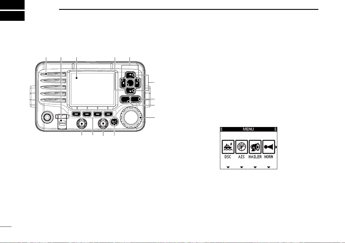
2 PANEL DESCRIPTION...................2–6
■Front panel......................................2
■Function display ..............................4
■Speaker Microphone.......................6
■Softkey function ..............................6
3 PREPARATION ..............................7–8
■MMSI code entry.............................7
■ATIS code entry ..............................8
4 BASIC OPERATION.....................9–14
■Channel selection ...........................9
■Receiving and transmitting............11
■Call channel entry .........................12
■Channel name entry .....................12
■Microphone Lock function .............13
■Adjusting the Backlight level .........14
■
AquaQuake water draining function
...14
5 SCAN OPERATION.................... 15–16
■Scan types ....................................15
■Setting Favorite channels .............16
■Starting a scan ..............................16
TABLE OF CONTENTS

1
1
OPERATING RULES
New2001
1
2
3
4
5
6
7
8
9
10
11
12
13
14
15
16
DPriorities
• Read all rules and regulations pertaining to call priorities,
and keep an up-to-date copy handy. Safety and distress
calls take priority over all others.
• You must monitor Channel 16 when you are not operating
on another channel.
• False or fraudulent distress calls are prohibited under law.
DPrivacy
• Information overheard, but not intended for you, cannot law-
fully be used in any way.
• Indecent or profane language is prohibited.
DRadio licenses
(1) SHIP STATION LICENSE
You may require a current radio station license before using
the transceiver. It is unlawful to operate a ship station which is
not licensed, but required to be.
If required, contact your dealer or the appropriate govern-
ment agency for a Ship-Radiotelephone license application.
This government-issued license states the call sign which is
your craft’s identification for radio purposes.
(2) OPERATOR’S LICENSE
A Restricted Radiotelephone Operator Permit is the license
most often held by small vessel radio operators when a radio
is not required for safety purposes.
If required, the Restricted Radiotelephone Operator Permit
must be posted or kept with the operator. If required, only a
licensed radio operator may operate a transceiver.
However, non-licensed individuals may talk over a transceiver
if a licensed operator starts, supervises, ends the call and
makes the necessary log entries.
A current copy of the applicable government rules and regu-
lations is only required to be on hand for vessels in which
a radio telephone is compulsory. However, even if you are
not required to have these on hand it is your responsibility to
be thoroughly acquainted with all pertinent rules and regula-
tions.

New2001
2
New2001
PANEL DESCRIPTION
2
■Front panel
CLEARMENU
ENT
CH
CH
t
u
y
we
r
i
q
o
!0!1
Function display (p. 4)
Speaker
qDISTRESS KEY [DISTRESS] (pp. 22, 23)
Hold down for 3 seconds to transmit a Distress call.
wENTER KEY [ENT]
Push to set the input data, selected item, and so on.
eLEFT AND RIGHT KEYS [Ω]/[≈]
➥Push to switch to the previous or next key function that
is assigned to the softkeys. (p. 7)
➥Push to select a desired character or number in the
table while in the channel name, position, MMSI code,
ATIS code programming mode, and so on. (pp. 8, 12,
21)
r
UP AND DOWN/CHANNEL SELECT KEYS [∫CH]/[√CH]
➥Push to select the operating channels, Menu items,
Menu settings, and so on.
➥While scanning, push to check Favorite channels,
change the scanning direction or manually resume a
scan. (p. 16)
tCLEAR KEY [CLEAR]
Push to cancel the entered data, or to return to the previ-
ous screen.
yMENU KEY [MENU]
Push to enter or exit the Menu screen. (p.
84
)
uDIAL/POWER SWITCH [PWR]
➥When the power is OFF, hold down for 1 second to turn
ON power.
➥Hold down for 1 second to turn OFF power.
➥Rotate to select the operating channels, Menu items,
Menu settings, and so on.
➥Push to set the input data, selected item, and so on.

New2001
3
2
PANEL DESCRIPTION
New2001
1
2
3
4
5
6
7
8
9
10
11
12
13
14
15
16
3
iCHANNEL 16/CALL CHANNEL KEY [16/C]
➥Push to select Channel 16. (p. 9)
➥Hold down for 1 second to select the Call channel. (p.
9
)
• The “CALL” icon appears when the Call channel is selected.
oSQUELCH DIAL
Rotate to adjust the squelch level.
!0 SOFTKEYS
Desired functions as described below can be assigned in
the Menu screen. (p. 87)
Scan [ ]* (p. 16)
Push to start or stop a Normal or Priority scan.
*This key does not appear in Dutch version transceivers.
Dualwatch/Tri-watch [ ] (p. 17)
Push once to start and stop a Dualwatch or Tri-watch scan.
AIS [ ]* (p. 73)
Push to display the AIS plotter on the left side of the display.
*Some versions do not have an AIS receiver.
Channel [ ] (pp. 9, 11)
Push to select a regular channel.
High/Low [ ](p. 11)
Push to set the power to high or low.
• Some channels are set to only low power.
Voice Scrambler [ ]* (p. 71)
Push to turn the Voice Scrambler ON or OFF.
• The “SBL” icon appears when the voice scrambler is ON.
*This key appears only when the voice scrambler unit is installed.
Voice Recorder [ ] (p. 71)
Push to playback recorded voice.
RX Hailer [ ] (p. 61)
Push to turn the RX Hailer mode ON or OFF.
LO/DX [ ]*
Push to turn the Attenuator function ON or OFF.
• The “LOC” icon appears when the Attenuator function is ON.
*This key appears only for Australian version transceivers.
Favorite channel [ ] (p. 16)
➥Push to set or clear the displayed channel as a Favorite
(Tag) channel.
➥Hold down for 3 seconds to clear or set all Favorite
(Tag) channels in the selected channel group.
Name [ ](p. 12)
Push to enter the channel name entry mode.
Backlight [ ](p. 14)
Push to enter the LCD and key backlight brightness ad-
justment mode.
Log [ ](p. 58)
Push to enter “RCVD CALL LOG” in the DSC CALLS menu.
!1 VOLUME DIAL
Rotate to adjust the volume level.

4
2PANEL DESCRIPTION
New2001
■Function display
!4
!6
!7
qwi
et
r!0
yo
u
!1
!3
!8
!9
@0
!5
!2
qBUSY/TRANSMIT ICON (p. 11)
➥The “ ” icon appears when receiving a signal, or
when the squelch is open.
➥The “ ” icon appears while transmitting.
wPOWER ICON (p. 11)
➥The “25W” icon appears when high power is selected.
➥The “1W” icon appears when low power is selected.
eRX HAILER ICON (p. 68)
Appears while in the RX Hailer mode.
rCHANNEL GROUP ICON (p. 10)
➥Shows which channel group is selected, a USA “USA”
International “INT” ATIS “ATIS” or DSC “DSC”*, de-
pending on the version.
*German transceiver version only
tCALL CHANNEL ICON (p. 9)
Appears when the Call channel is selected.
yDUPLEX ICON (p. 10)
Appears when a duplex channel is selected.
uFAVORITE CHANNEL ICON (p. 16)
Appears when a Favorite (Tag) channel is selected.
iMESSAGE ICON
Blinks when there is an unread DSC message.
oGPS ICON
➥Stays ON when the GPS receiver is activated and valid
position data is received.
➥Blinks when invalid position data is being received.
!0 SWITCH ICON (p. 62)
Appears when the “CH 16 SWITCH” in DSC Settings is set
to OFF.
!1 LOW BATTERY ICON
Blinks when the battery voltage drops to approximately
10.8 V DC or less.
!2 CHANNEL NUMBER READOUT
Displays the selected operating channel number.
• When a simplex channel is selected, “A” or “B” appears.
!3 CHANNEL NAME FIELD
The channel name appears, if entered. (p. 12)

1-1-32 Kamiminami, Hirano-ku, Osaka 547-0003, Japan
A-7130D-1EU-e
Printed in Japan
©2014–2017 Icom Inc.
Printed on recycled paper with soy ink.
Other manuals for IC-M506
5
This manual suits for next models
1
Other Icom Transceiver manuals
Popular Transceiver manuals by other brands

Kenwood
Kenwood TH-28A instruction manual

Micom
Micom RM125 owner's guide

MDS
MDS MDS 4710 Series Installation and operation guide

City Theatrical
City Theatrical Multiverse Vero 7400-5903 user manual

Thrane&Thrane
Thrane&Thrane TT-3020B Technical reference manual

ELANsat Tech
ELANsat Tech DRF-TR001 user manual