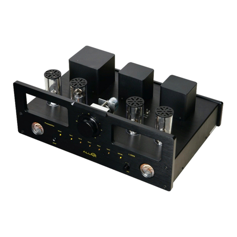
Auricsound A7 User manual

1
User Guide

2 3
Contents 3
4
Dimensions 5
Front panel layout 6
Back panel layout 8
Operating environment 10
Connecting and wiring 11
Contents
Origenae is not responsible for any damages due to external
causes, including but not limited to, improper use, problems with
electrical power, accident, neglect, alternation, unauthorized
repair, improper installation or improper testing. This manual
should be read before installation and operation.
CAUTION: TO REDUCE THE RISK OF ELECTRIC SHOCK, DO NOT
REMOVE COVER (OR BACK). NO USER SERVICEABLE PARTS INSIDE.
REFER TO QUALIFIED AUTHORIZED SERVICE PERSONNEL FOR
SERVICING.
equilateral trainagle is intended to alert the user to the
presence of uninsulated “dangerous voltage” within the
constitute a risk of electric shock to persons.
The exclamation point within an equilateral triangle is intended
to alert the user to the presence of important operating
and maintenance (servicing) instructions in the literature
accompanying the product.
WARNING: DO NOT EXPOSE THIS PRODUCT TO RAIN OR MOISTURE.
IF EXPOSED THERE IS AN INCREASED RISK OF FIRE OR ELECTRIC
SHOCK.
RISK OF ELECTRIC SHOCK
DO NOT OPEN
Remote controller 12

4 5
•
• 150 watt per channel RMS at 4 ohm
• 80 watt per channel RMS at 8 ohm
• Frequency response : 5Hz ~ 120KHz(-3dB)
• S/N Ratio : > 85db
• Total harmonic distortion : <0.05%( 20KHz / 8ohm)
• Inputs :
L1 Gold RCA auxillary audio input
L2 XLR 4 Balanced audio input
Gold 6.35mm Headphone audio output
XLR 4 Balanced audio output
•
Output : Gold binding post pairs speaker output
Vacuum Tube PreAmplifier
• Class A HIFI PreAmplifier Vacuum Tube
Power Adaptor
• Rated Input Voltage : 100Vac / 240Vac
• Input Voltage Range : 90Vac to 264Vac
• Input Frequency Range : 47Hz to 63Hz
Specifications Dimensions
193mm
59mm
155mm
193mm

6 7
Front panel layout
5 - Volume status LED
2 - Power button
6 - IR Receiver
The IR remote receiver window.
1 - Headphone jack
The 6.35mm TRS headphone jack allows a pair of headphones that have the standard
The Volume status LED can be set to either high or low from minimum 00 to maximum 99,
by rotating the Knob, and Show the L1 or L2 Audio input status LED. When press once the
Konb and flash LED in so i t is in a Volume Mute status.
Pressing this Knob lasts for approximately two seconds to turns power toamplifier ON,
to turn the power to the amplifer OFF press the Knob again for approximately two seconds.
3 - Volume adjuster
turned the Knob to the left position the audio volume will be decreases .
The audio volume progressively increases as the adjuster is turned until it
reaches the right position where the volume is at its maximum level.
4 - Audio Input selector
The input selector allows one of the two available audio inputs to be selected. To
select an audio input Press the Knob twin times quickly to select L1 or L2 inputs to
the desired audio input.

8
Back panel layout
8 - Left speaker output terminals
The left speakers for audio output can be connected to these terminals.
1 - L1 RCA Audio input jacks
An external tuner audio device that has RCA audio output can be connected to these
selected using the input selector on the front panel.
2 - L2 XLR 4 Pin Balanced input jacks
A Balanced device that has XLR 4 Pin audio output can be connected to these
can be selected using the input selector on the front panel.
3 - XLR 4 Pin Balanced Output jacks
6 - USB jack
The USB interface to provide wireless subwoofer dongle power and upgarde service only
5 - DC Power socket
The supplied power adaptor is connected to this socket and to a power outlet in order
device.
7 - Right speaker output terminals
The right speakers for audio output can be connected to these terminals
*Any audio device with standard RCA audio output can be connected to either the DACs, compact
disc or auxillary RCA input jacks.
XLR 4 Pin audio so that it can be used as an audio input to the amplifier, the device
An external Balanced audio device that has XLR audio intput can be connected to these
XLR 4 Pin audio so that it can be used as an audio output from the amplifier.
4 - Subwoofer output terminals
The subwoofer for audio output can be connected to these terminals.

10 11
Operating environment Connecting and wiring
the following conditions occur:
• Direct exposure to sunlight
• High dust volume environments
• Places where mechanical vibrations may occur
• On an unstable surface
• Near sources of heat generation such as heaters
• Very humid of poorly ventilated environments
• Where the top vents are obstructed
To allow proper disappation of heat please ensure that the minnimum clearance below
Units: millimeters
For further information on the connection information about your external input
devices please refer to the documentation that came with the device.
XLR 4pin
Balanced
Audio Input
XLR 4pin
Balanced
Audio Output
Upgrade Service/
Wireless Subwoofer
Power ONLY
DAC / CD Player / AUX
SPEAKERS CONNECTION AND BANANA PLUG INSTALLATION
One of the most common ways of connecting speakers
to an amplier is through the use of binding posts.
using banana plugs, these simple connection points will work
with any 10-gauge speaker cable, allowing you to easily
dictate the length of wire needed for your particular setup.
BARE SPEAKER WIREBANANA PLUG SPEAKER CABLE
FOR BANANA PLUG ONLY

12 13
Remote Controller
A7 RM-1 Remote
L1 Audio Input
Volume control
L2 Audio Input
Mute
AP Index
P.S. Please install the battery inside before using the remote controller.
Battery model “CR2025 Lithium Battery”
Table of contents

