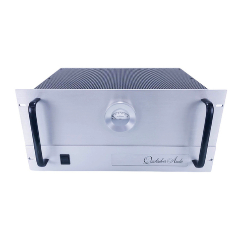
Lawson 110A Mic Pre/DI User manual

Operation Guide
Lawson 110A Mic Pre/DI
Lawson,Inc.
Relive the Magic™
2739 Larmon Avenue
Nashville,TN 37204 U.S.A.
615-269-5542
Fax 615-269-5745
www.LawsonMicrophones.com
Notes

Warranty
One-Year Limited Warranty
Lawson Incorporated microphones purchased in the U.S.A.from Law-
son,Inc., or its authorized agents are warranted for one year from date
of purchase by Lawson,Inc., to be free of defects in materials and
workmanship (vacuum tubes excluded). In event of such defect,prod-
uct will be repaired promptly without charge or,at our option,re-
placed with a new product of equal or superior value if delivered to
Lawson,Inc., prepaid,together with the sales slip or other proof of
purchase date.Prior approval from Lawson,Inc., is required for return.
This warranty excludes vacuum tubes,defects due to normal wear,
abuse,shipping damage,or failure to use product in accordance with
instructions.This warranty is non-transferable and is void in the event
of unauthorized repair or modification.
For return approval and shipping information,contact Lawson,Inc.,
2739 Larmon Avenue,Nashville,TN 37204 U.S.A.
To validate your warranty,please return the enclosed registration card
or log on to www.lawsonmicrophones.com/register.html.
CAUTION!
* During the warranty period,repairs should be referred to
Lawson,Inc.After expiration of the warranty,for safety
reasons any repairs should be referred to Lawson,Inc., or to
qualified service technicians.
Safety Precautions

Introduction
Congratulations and thank you for purchasing the
Lawson 110A Mic Pre/DI.Lawson products are hand-
crafted in the USA by real people with pride to give
you many years of service and enjoyment.
To familiarize yourself with the special features of
your Lawson 110A Mic Pre/DI,please take the time
to read this manual.
Your Lawson 110A Mic Pre/DI Serial Number:
Created and checked by: ???
Date: ???
Lawson 110A Mic Pre/DI Serial Number: ???
Specifications

The Lawson 110A Mic Pre/DI is a blast from the past.The Lawson
110A Mic Pre/DI is a two-channel mic pre based on the original vin-
tage Spectra Sonics (patented in 1965) 110A discrete pre amp card.
The Lawson 110A Mic Pre/DI also includes Hi Z direct instrument in-
puts that utilize discrete super low noise field effect transistors
(FETs). In the DI mode,the output of the FETs feeds the input of
the 110A card for adjustable gain.
The Lawson 110A Mic Pre/DI features:
1. Two channels with large VU meters,switchable 48V phantom,and
phase reversal switch;
2. Lundahl transformers on input and output with special attention
to the impedance ratio of the input transformer;
3. Film capacitors used on I/O of 110A amplifier card (instead of low
quality electrolytic capacitors used in the original);
4. Balanced continuously variable input pad (long life high quality
conductive plastic dual potentiometers);
5. Ruler flat frequency response from 20 Hz to 20 kHz;
6. Modest 50dB gain (designed specifically for condenser micro-
phones);
7. Extremely low distortion,virtually unmeasurable;
8. Overload recovery time is 1micro second for up to 1000% over-
load;
9. Hand-selected low noise discrete transistors matched for beta;
10. Only the very finest components including Neutrik™ gold-plated
XLR connectors,1% metal film resistors,highest quality long frame
1/4” jacks for DI,Gotham™ shielded cable used for internal wiring,
toroidal transformer on power supply,anodized aluminum front
panel with permanent lettering;
11. Designed for ease of use (straightforward uncomplicated layout
of controls).
Features
The Lawson 110A Mic Pre/DI contains two separate channels.
Each channel has five controls.Channel One controls and meter
are located on the left.Channel Two controls and meter are lo-
cated on the right.
The five controls are (refer to front panel shown on next page):
1. Rotary Gain Control Knob
2. Microphone/DI Selection Switch
3. 48 Volt Phantom On/Off Switch
4. Phase Switch (Positive/Negative)
5. Meter Zero Adjustment
1. Rotary Gain Control Knob
The gain control adjusts the level of the microphones or DI (in-
struments).
2. Microphone/DI Selection Switch
Selects the input source: either microphone (rear panel XLR)or
DI (front panel 1/4” guitar jack).
3. 48 Volt Phantom On/Off Switch
Turns on or off 48 volt phantom power for microphones that re-
quire phantom powering.If you are using a vacuum tube mic,
switch to off.
4. Phase Switch
Changes the phase/polarity of the mic/DI (0º or -180º). The nor-
mal position for this switch is the “+” position.
5. Meter Zero Adjustment
Controls the position of the meter needle at rest.With no signal,
the needle should rest directly on the line just below -20. This
adjustment requires a small slotted-blade screwdriver.Insert the
screwdriver into the meter adjustment hole and gently rotate
slightly clockwise/counter-clockwise until the needle rests on
the line just below -20. Adjustment of this control rarely needs
attention.
Controls

Plug an additional XLR cable into the corresponding output
(Channel One or Channel Two)located on the rear of the unit.
Plug the other end of this cable into the line input of your con-
sole/audio workstation.
Switch MIC/DI to MIC.If you are using a phantom powered mi-
crophone,switch 48V to on.If you are using a tube mic,switch
48V to off.
Switch Phase Reversal to “+” normal position.
With a vocal or other sound source performing into your micro-
phone,adjust the front panel gain control clockwise until a nor-
mal level is indicated on the VU meter.Remember,VU meters
are not peak indicators but display average levels.Adjust the
gain control so that the peak reading meters on your
console/workstation are below digital zero.Some peak levels
can be 15 dB higher than that displayed on an “averaging”VU
meter.
DI/Instrument
Turn gain controls to minimum (counter clockwise). Then
switch MIC/DI to DI.
Switch Phase Reversal to “+” normal position.
Plug an instrument (keyboard,guitar,bass,etc.) into the 1/4”
jack on the front panel using a standard guitar cord.Be sure the
volume control at the instrument is turned to maximum thereby
insuring the highest signal-to-noise ratio.
Plug an additional XLR cable into the corresponding output
(Channel One or Channel Two)located on the rear of the unit.
Plug the other end of this cable into the line input of your con-
sole/audio workstation.
With the instrument performing,adjust gain control clockwise
until a normal level is indicated on the VU meter.Remember to
check peak readings on your console/workstation as VU meters
don’t indicate instantaneous peaks.
Inputs
Two mic inputs (one per channel)are located on the rear panel
(marked Channel 1Mic Input and Channel 2Mic Input). Each mic
input is a standard 3-pin XLR female connector (pin 2positive).
There are two DI inputs (one per channel)located on the front
panel.Each DI input requires a 1/4" standard guitar plug.The DI in-
puts are labeled “HI Z”indicating they are high impedance inputs
that would normally be encountered with guitar,bass,etc.
Outputs
There are two 600 ohm balanced outputs (one per channel)located
on the rear panel.Each output is a standard 3-pin male XLR (pin 2
positive).
There are two unbalanced outputs (one per channel)located on the
rear panel.Each unbalanced output is a standard 1/4" guitar jack.
This output is designed to feed a guitar/bass amp for monitoring
purposes.This is a high impedance (HI Z)output.This output level is
fixed i.e.is not affected by the gain control settings on the front
panel.
Inputs and Outputs
Setup Instructions
Verify the 115/230VAC voltage selector is set for your AC outlets.In
the USA,115VAC would be the norm.In Europe,230VAC would be
the norm.
Connect the power cord to the power connector located on the rear
of the unit.Make sure the power cord is seated firmly into the rear
power connector.Turn the unit on via the On/Off Switch.The me-
ters will illuminate.
Microphones
Turn gain controls to minimum (counter clockwise). Using a 3-pin
XLR cable,plug a microphone into one of the female XLR inputs
(Channel One or Channel Two)located on the rear of the unit.

Table of contents
