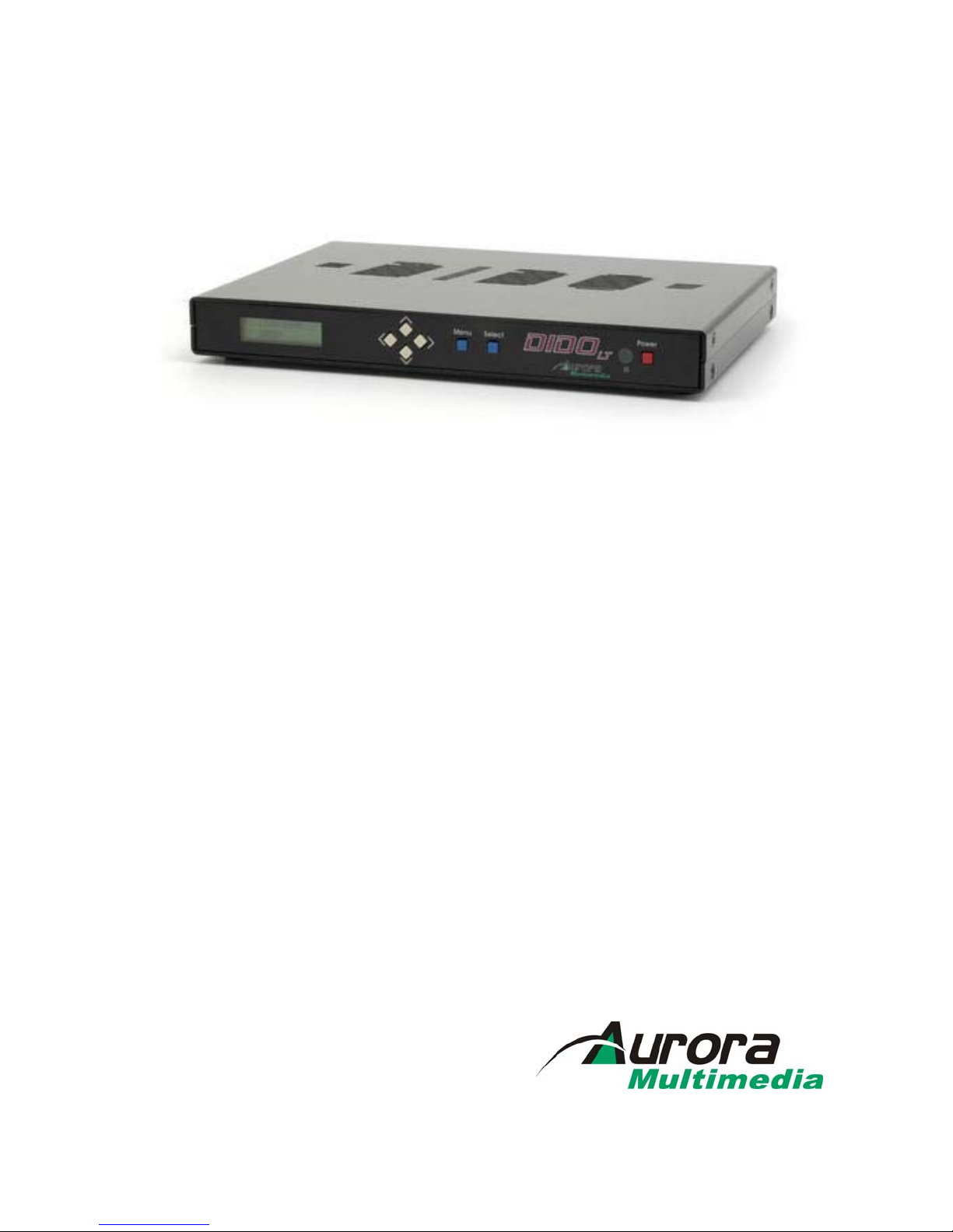
DIDO LT Installation Manual
I
TABLE OF CONTENT
INTRODUCTION.........................................................................................................................................2
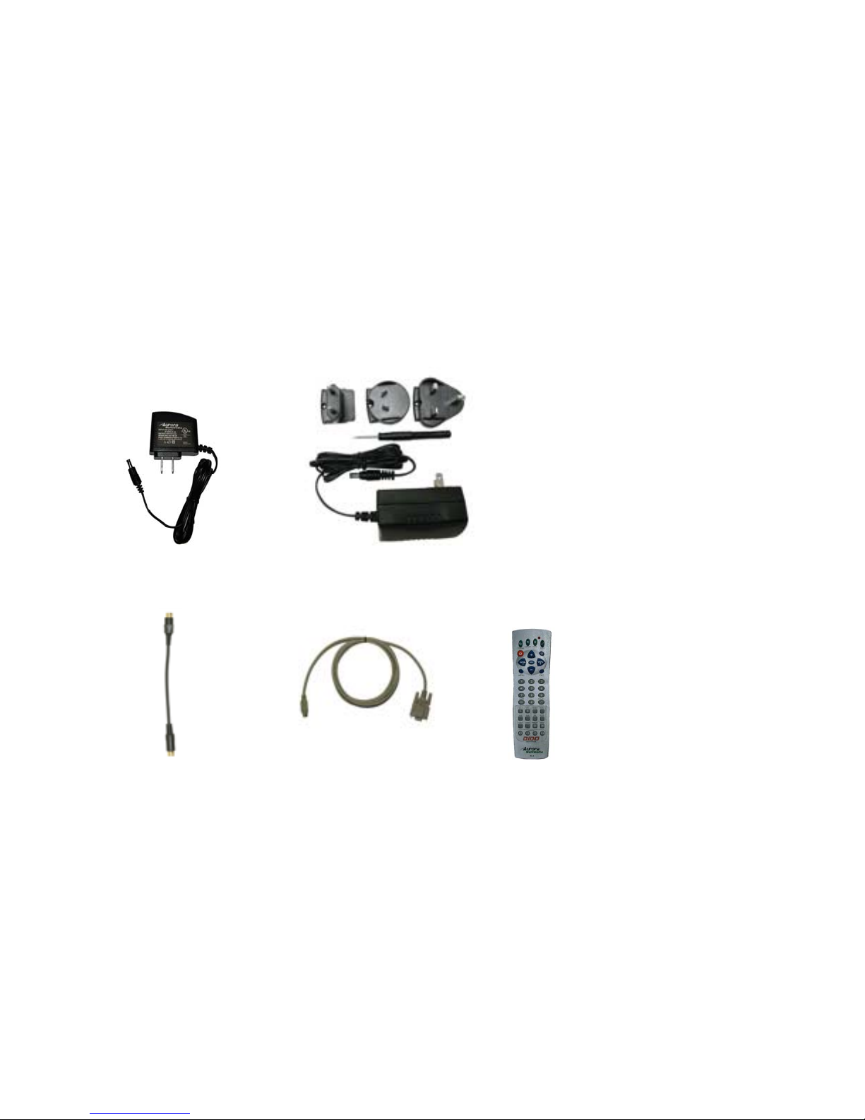
ACCESSORIES.............................................................................................................................................4
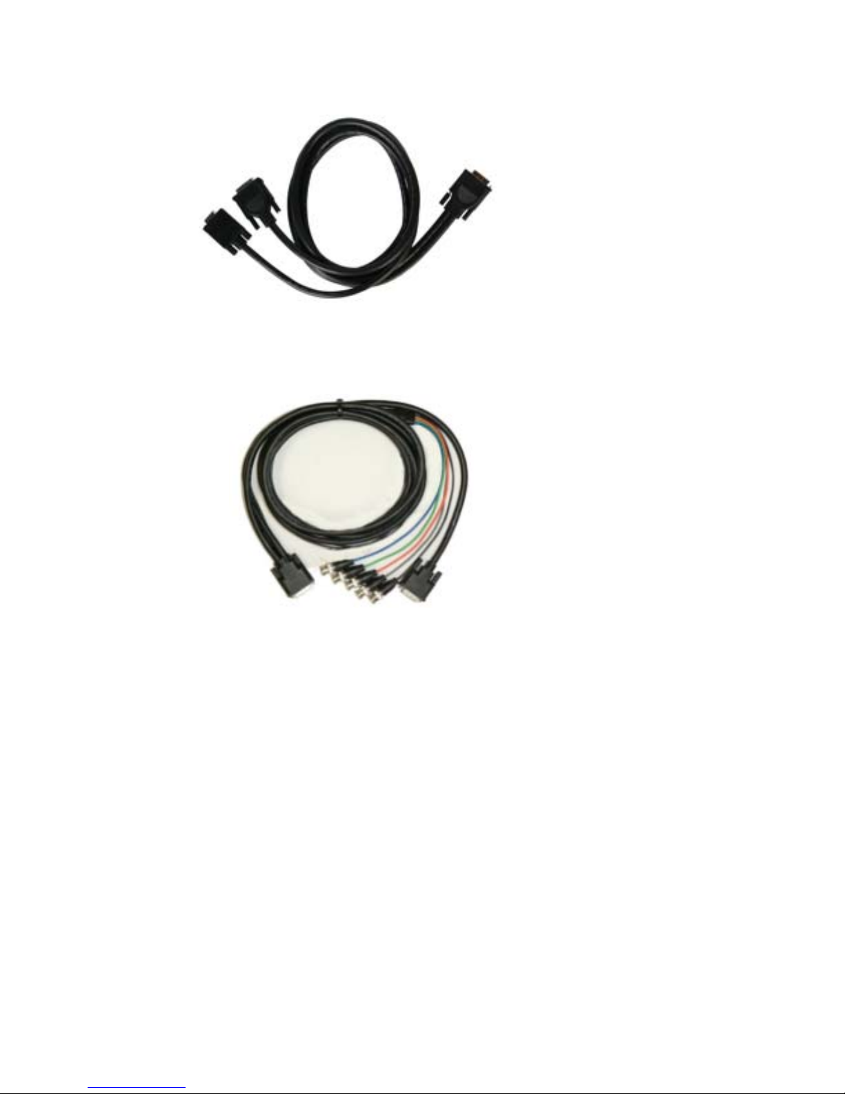
OPTIONAL ACCESSORIES..............................................................................................................................5
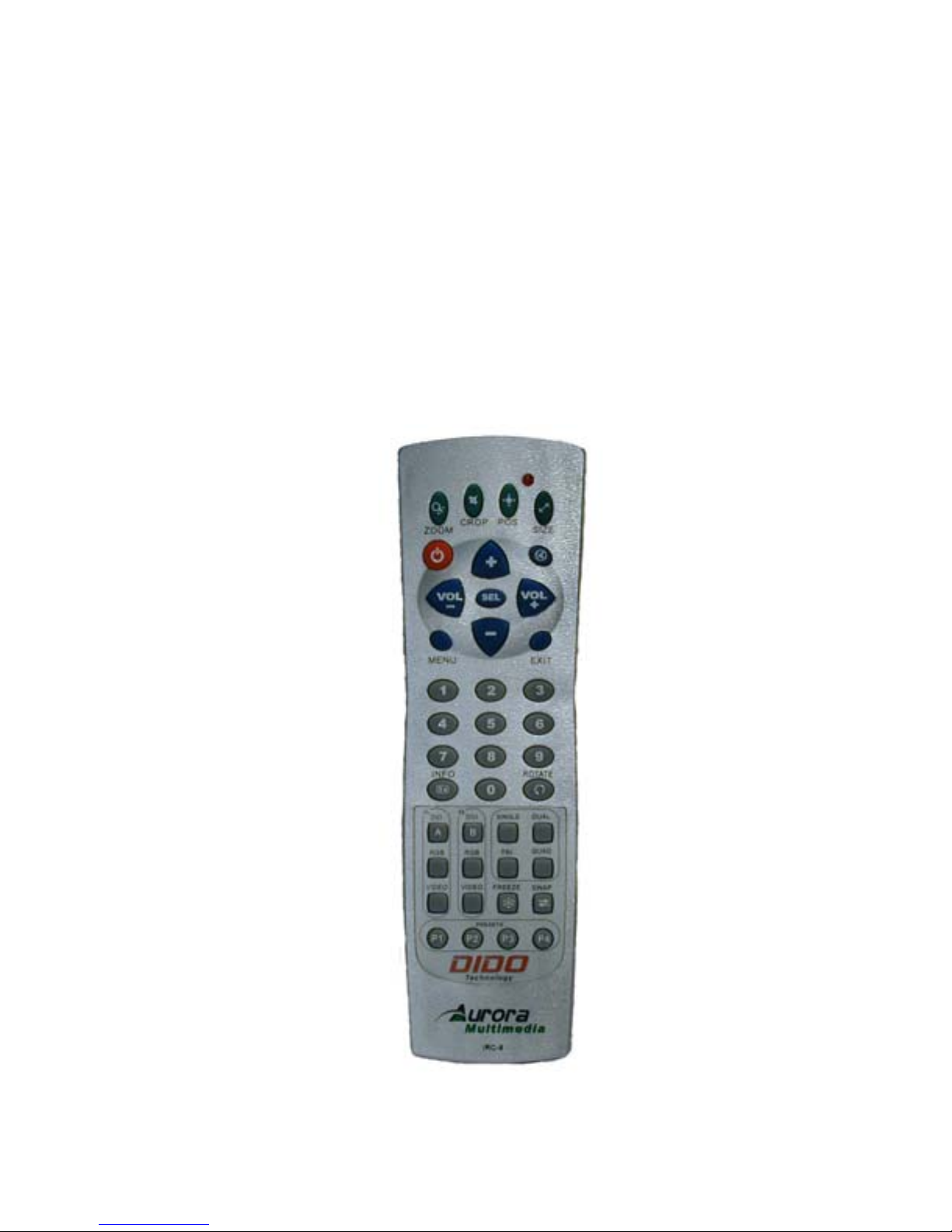
IR REMOTE AND BASIC KEY FUNCTIONS.........................................................................................7
QUICK START GUIDE...............................................................................................................................8
LCD / KEYPAD.............................................................................................................................................9
CONNECTIONS ...........................................................................................................................................9
A/V &CONTROL CONNECTORS..................................................................................................................10
POWER CONNECTOR ...................................................................................................................................10
EXAMPLES CONNECTIONS..........................................................................................................................10
OPERATING THE DIDO LT....................................................................................................................12
REMOTE CONTROL FUNCTIONS..................................................................................................................12
MENU STRUCTURE.....................................................................................................................................13
1.1.1 MAIN MENU...............................................................................................................................13
1.1.2 WINDOW SETUP .........................................................................................................................14
1.1.3 INPUT SETUP ..............................................................................................................................16
1.1.4 LAYOUT SETUP...........................................................................................................................16
1.1.5 OUTPUT SETUP...........................................................................................................................18
1.1.6 PRESET SETUP ............................................................................................................................18
1.1.7 SYSTEM SETTINGS......................................................................................................................19
SIGNAL TIMING.......................................................................................................................................22
1.1.8 TIMER AND SCHEDULER .............................................................................................................22
VIDEO WALL FUNCTIONALITY..........................................................................................................24
CONTROL SOFTWARE...........................................................................................................................25
8 TROUBLESHOOTING...........................................................................................................................26
FIRMWARE UPDATE...............................................................................................................................27
CLONING....................................................................................................................................................28
RS-232 PROTOCOL...................................................................................................................................29
SPECIFICATIONS.....................................................................................................................................35
SUPPORTED VIDEO TIMING ........................................................................................................................35
POWER SOURCE..........................................................................................................................................36
CONNECTION TERMINALS...........................................................................................................................36
DIMENSIONS...............................................................................................................................................37
WEIGHT......................................................................................................................................................37
LIMITED LIFETIME WARRANTY........................................................................................................38
FCC PART 15 STATEMENT....................................................................................................................39
INDEX..........................................................................................................................................................40