Aurora 224 User manual

1
aurora224
ProductManualv1.0
www.auroramixer.com

2
Contents
Connection........................................................................................................................ 3
Assembly........................................................................................................................... 4
In Circuit Programming.................................................................................................... 5
Protocol.............................................................................................................................. 6
Selecting \ Changing the Aurora USB Comport.......................................................... 7
Aurora PD (Pure Data) Setup Introduction .................................................................. 9
Aurora Max5 Setup........................................................................................................ 13
Hardware......................................................................................................................... 17

3
Connection
A USB A to B mini cable is used to connect the mixer to the computer. Maple
Midi or MidiYoke needs to be installed prior to operating the mixer. The control
software, either Max5 or Pure Data is also needed. Please review the section on
setting up either Max or PD to determine which software to use. The diagram in
a typical setup is included below.
Once the drivers are installed, you can simply plug aurora into the computer’s
USB port. NOTE: Plugging aurora into a low power USB hub will make the
device operate incorrectly.
To operate aurora’s ambient lighting with Max5, the Max5 patch requires tempo
input. In the diagram above, sharing the tempo with Max is accomplished using
the rewire interface.
Ableton Live, or another rewire host, must be started before starting Max.
Additionally, Max must be configured to receive data. This is accomplished
choosing “rewire” under Max’s DSP Setting menu.

4
Assembly
The Aurora 224 is easy to assemble. Start by snapping the button caps (7) onto the PCB
assembly (6). Then align the bottom panel (9) making sure the mounting holes line up
with PCB. If they don’t, flip the bottom panel or rotate it so that they do, making sure you
stack them as shown. Once they are aligned, insert the female #8-32 threaded standoffs
(10) into the bottom panel as shown. They should fit snuggly. Now place the large
spacers (8) over the standoffs. Place the PCB on top, and fasten it down with the four
little screws (5). They should be snug. Now place the small spacers (4) and lay the top
panel (3) down. Drive the long #8-32 screws (2) into the outer four standoffs. Flip the
entire assembly over and place an adhesive backed rubber foot (11) on each corner.
Finally turn all the rotary potentiometers to the left or right, and then press on the knobs
(1). Now you have your very own color blasting midi mixer.

5
In Circuit Programming
The source code for both PIC MCUs is compatible with Source Boost’s BoostC
PIC compiler: http://www.sourceboost.com/
Olimex’s MCP-USB is an MPLAB compatible programmer. They are available
from Sparkfun: www.sparkfun.com
In circuit programming is accomplished using the ICSP1 and ICSP2. Refer to the
schematics to see the pinout of the header, it is compatible with the MCP-USB
but will function with other programmers.
Additionally, when compiling code, enure that your configuration bits match the
config bits of the source on the website.
DO NOT LEAVE THE AURORA PLUGGED INTO THE USB PORT WHEN
ATTEMPTING TO PROGRAM

6
Protocol
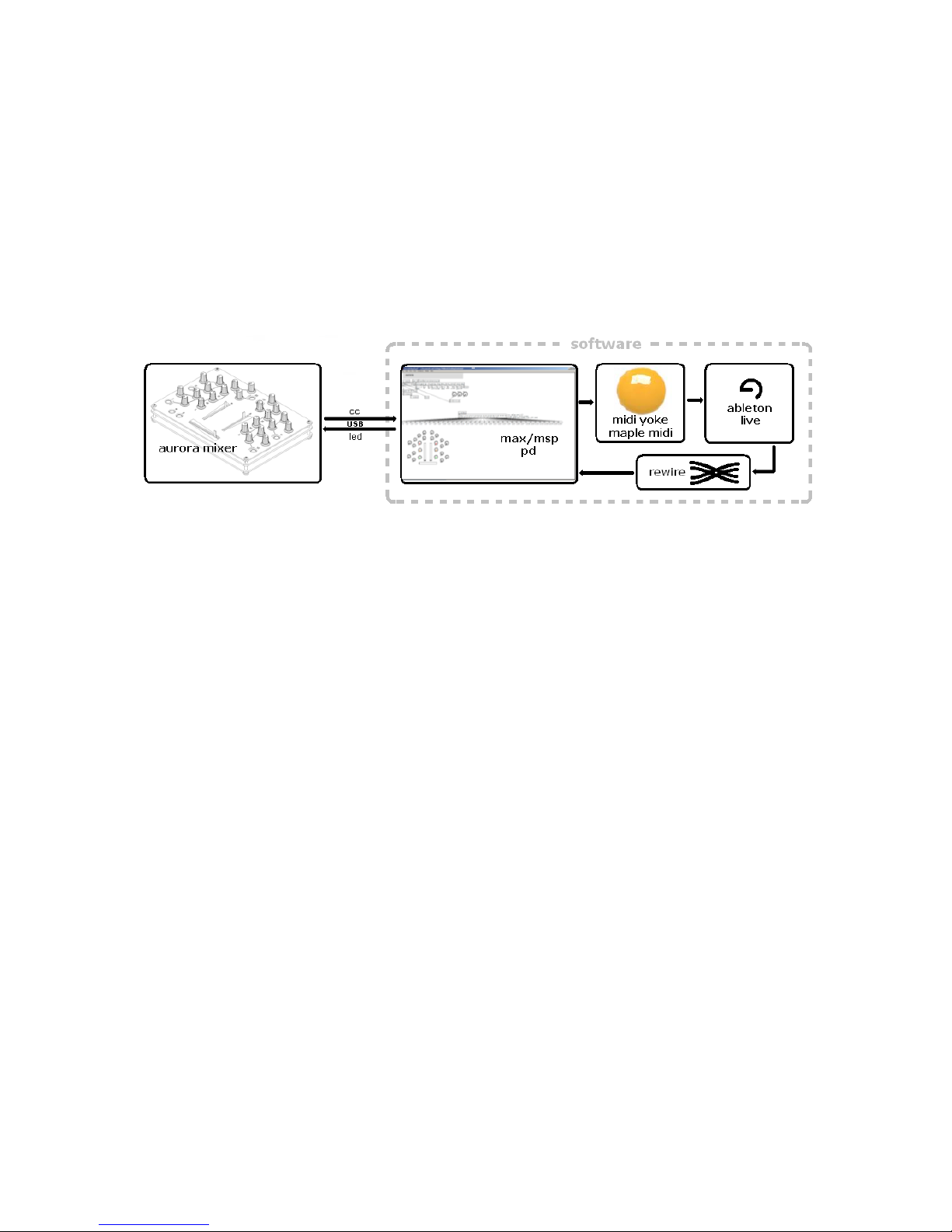
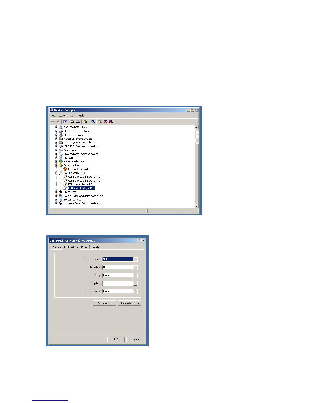
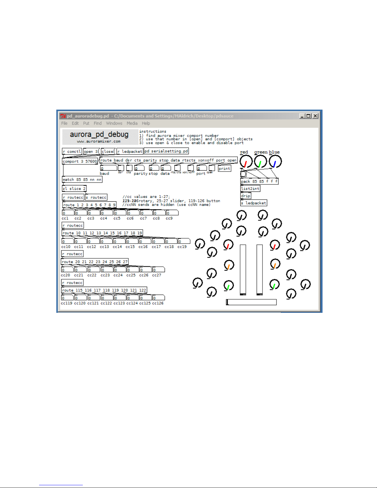
Aurora uses two simple serial protocols for sending and receiving data at a baud rate of
57600. These two protocols can be easily sent and received in MAX/MSP and Pure Data
(pd) by using the virtual COM port created when the Aurora is connected to your
computer via a USB cable. Take a look at our MAX/MSP or pd patches for examples.
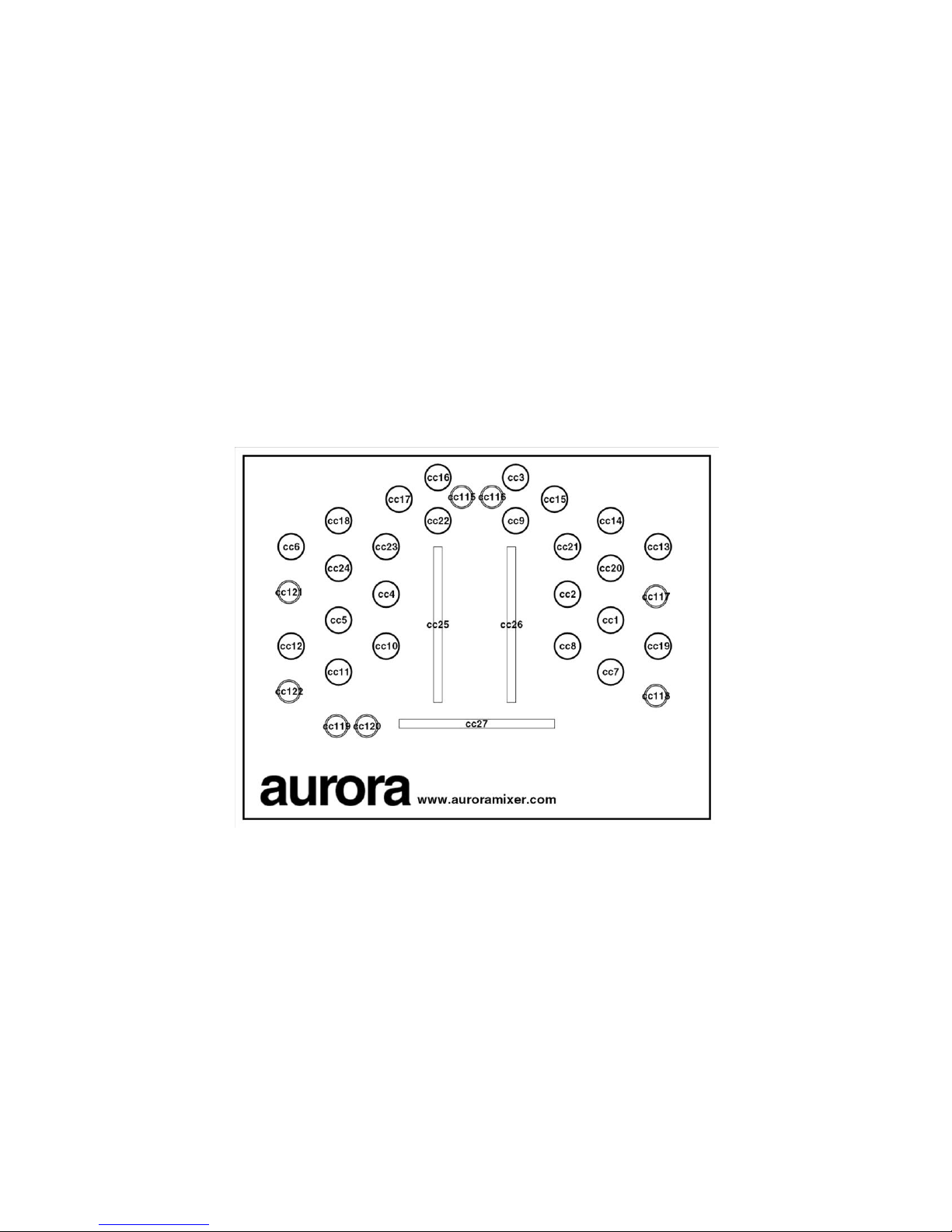
Aurora sends packets when changes occur in slider, knob, and button position. For each
individual slider, knob, or button, a packet is sent in the following format:
[0x55] [0x55] [cc] [value]
where [0x55] is a hexadecimal 55 (decimal 85), [cc] is the corresponding MIDI change
control, and [value] is the position. In concurrence with MIDI standards, [value] has a
valid range of zero to 127 (decimal). Below is a mapping of the CC values.
The ambient lighting system can be controlled by sending packets to Aurora. The
ambient lighting system uses red, green, and blue LEDs to create colors. The color can
be manipulated by changing the ratio of red, green, and blue. Aurora accepts packets in
the following format:
[0x55] [0x55] [red] [green] [blue]
where [0x55] is a hexadecimal 55 (decimal 85), [red] is the red intensity, [green] is the
green intensity, and [blue] is the blue intensity. The three colors have valid ranges of
zero to 255 (decimal).

7
Selecting \ Changing the Aurora USB Comport
Knowing the comport number is important. To check the comport, right click My
Computer and click Properties. Under System Properties, click the Hardware tab and
then click Device Manager.
Scroll down and expand Ports. Here you will see the USB Serial Port you installed. Right
click this new port and click on properties.
You will now see this, select the Port Settings tab and click on Advanced:

8
You can change the com port here:

9
Aurora PD (Pure Data) Setup Introduction
The aurora / PD interface allows the mixer to transmit and receive data using the USB
port. The PD interface receives data from the mixer and converts its into MIDI CC
messages. The PD interface transmits red, green, and blue color data using a scale of 0-
255 to indicate brightness. Install all drivers before plugging in the USB mixer. \
Setup of Drivers Several driver/software installations are needed to use to the PD
interface. Make sure to download and install these files before using the mixer:
PD-Extended: Pd (aka Pure Data) is a real-time graphical programming environment
that is part of the Max family of graphical patcher programming languages for audio,
music and multimedia. http://at.or.at/hans/pd/installers.html
FTDI Chip VCP: this driver controls the serial port
http://www.ftdichip.com/Drivers/VCP.htm
Maple Virtual Midi Cable: This allows you to transmit MIDI to other PC programs.
Note:PD is compatible with Maple. It will not function using MidiYoke
http://www.hurchalla.com/Maple_driver.html
After these drivers are installed, plug in the mixer. Windows will find a serial port device
and assign a serial port number to the device. Make sure you know how to change the
device comport if necessary.
PD Setup Extract the downloaded PD files anywhere on the computer. Double click the
.pd files to begin running the program. PD will start up and look something like this:

10
Check to make sure that Mapel Midi Out ports are showing up. If not, install the Maple
Midi driver.
aurora_pd_debug This file can be used to read out the CC data coming from the mixer,
as well as test the LEDs on the PC board.
To specify the comport in PD, simply press ctrl+e to enable editing of the patch. Click on
the object [comport] and type in the comport number of the device. Comports 1-4 are
recommended. Save your patch file to save the changes you made.

11
pd_auroramidi.pd \ pd_auroramidi_abletonlive.pd These files read CC data from the
mixer and translate them into MIDI CC values. CC values 119 and 120 are handled
differently between these programs.
Use pd_auroramidi_abletonlive.pd if you plan on using Live. The program looks like this:
PD’s midi output port must be specified, the Maple MIDI drivers should be installed. To
set up the MIDI output click Media and select MIDI settings.

12
Select the output device and pick one of the MIDI outputs (this port number is important,
your other MIDI programs will need to be setup to read this port)
When you are finished it should look like this
:
The device is now configured. Enjoy.

13
Aurora Max5 Setup
Introduction
The aurora / Max5 interface allows the mixer to transmit and receive data using the USB
port. The Max interface receives data from the mixer and converts its into MIDI CC
messages. The Max5 interface transmits red, green, and blue color data using a scale of
0-255 to indicate brightness. Install all drivers before plugging in the USB mixer.
The Max5 patch uses lsynth to generate patterns of light when Max is receiving data
from rewire capable software. For a better description visit visiphon.com and view
projects.
The two files you can download are either
max5_aurorafiles_fullcontrol.zip
max5_aurorafiles_preset.zip
Unzip these anywhere you want to run the software.
6/27/08 No run time version of max5 is available, when it is, a run time of this
patch will be available.
These files are needed:
Max5: www.cycling74.com
FTDI Chip VCP: this driver controls the serial port
http://www.ftdichip.com/Drivers/VCP.htm
MidiYoke: This allows you to transmit MIDI to other PC programs. Note:PD is not
compatible with Midi Yoke.
http://www.midiox.com/
After these drivers are installed, plug in the mixer. Windows will find a serial port device
and assign a serial port number to the device. Make sure you know how to change the
device comport if necessary.
Usage
If all the drivers are installed and the software is configured correctly (see below).
Simply select the serial port and specify the MIDI port on which the data will output. If
you are using Max5 with Ableton Live to create effects using the ambient lighting, make
sure your DSP status is setup for rewire (see below). To start the lsynth, press start
visuals. When Ableton live begins playing, it will send tempo information to Max5 and in
turn Max will control the LEDs on aurora.

14
Select the port of the device and open or close the serial comport.
Press the button to Set Midi and select your MIDI output port, this port should also be
setup in your favorite Midi Program.
The rest of the on screen display is used for lsynth, aurora’s ambient lighting engine.
Depending on which Max5 patch you downloaded, the light effects will be either random
but tempo synchronized or controllable and tempo synchronized. To control the lsynth
engine with the mixer, simply rotate a knob and click the button above an ORSET,
RRSET, OR RGSET. All 9 of these parameters can be assigned.

15
A few things in Max should be set up before you begin:
Make sure your MIDI drivers are set up.

16
If you plan on using aurora with Rewire, make sure to setup your DSP Status window to
use rewire as it is below.

17
Hardware
These images of the PCBs call out the position and location of the important ICs and
components on the boards. Images of the PCBs are found at www.auroramixer.com
Figure 1 Bottom View of the PCB
Figure 2 Measurement Circuit

18
Figure 4 Top of PCB.
Figure 3 Power Management
Table of contents