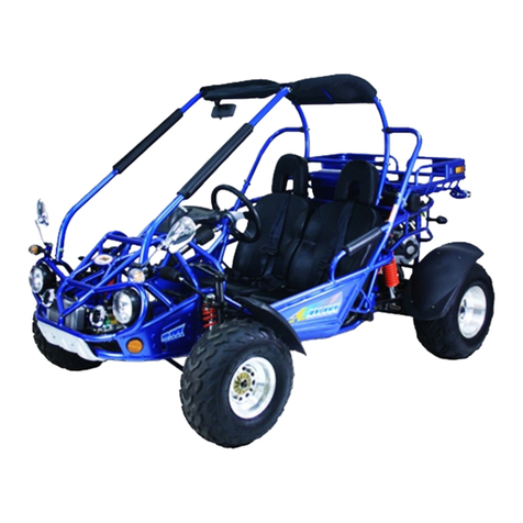
AUSA M-50 x 4 Instruction manual

1
AUSA M-50 x 4
ROTAX ENGINE WORKSHOP
MANUAL


Section 03 ENGINE
Subsection 01 (TABLE OF CONTENTS)
VMR2004_154_03_01ATOC.FM 03-01-1
TABLE OF CONTENTS 0
TROUBLESHOOTING............................................................................................................ 03-02-1
COOLING SYSTEM ........................................................................................................... 03-02-1
MAGNETO SYSTEM ......................................................................................................... 03-02-2
LUBRICATION.................................................................................................................... 03-02-4
CYLINDER AND HEAD ...................................................................................................... 03-02-6
CRANKSHAFT AND BALANCER SHAFT.......................................................................... 03-02-7
GEARBOX .......................................................................................................................... 03-02-7
REWIND STARTER ............................................................................................................ 03-02-9
CVT..................................................................................................................................... 03-02-10
ENGINE GENERAL ............................................................................................................ 03-02-15
LEAK TEST............................................................................................................................. 03-03-1
GENERAL VERIFICATION ................................................................................................. 03-03-1
LEAK TEST PROCEDURE .................................................................................................. 03-03-1
PREPARATION AND TEST................................................................................................ 03-03-1
INSTALLATION.................................................................................................................. 03-03-3
REMOVAL AND INSTALLATION .......................................................................................... 03-04-1
GENERAL ........................................................................................................................... 03-04-3
ENGINE REMOVAL ........................................................................................................... 03-04-3
ENGINE INSTALLATION ................................................................................................... 03-04-8
ANTI-VIBRATION SYSTEM............................................................................................... 03-04-9
EXHAUST SYSTEM .......................................................................................................... 03-04-9
SHIFTING SYSTEM............................................................................................................ 03-04-10
COOLING SYSTEM ............................................................................................................... 03-05-1
WATER PUMP.................................................................................................................... 03-05-1
COOLING SYSTEM ........................................................................................................... 03-05-2
GENERAL ........................................................................................................................... 03-05-3
COOLING SYSTEM LEAK TEST ....................................................................................... 03-05-3
INSPECTION ......................................................................................................................03-05-3
DRAINING THE SYSTEM .................................................................................................. 03-05-4
COOLANT REPLACEMENT............................................................................................... 03-05-4
THERMOSTAT ................................................................................................................... 03-05-5
WATER TEMPERATURE SWITCH..................................................................................... 03-05-6
WATER PUMP HOUSING ................................................................................................. 03-05-6
WATER PUMP IMPELLER ................................................................................................. 03-05-7
WATER PUMP SHAFT....................................................................................................... 03-05-7
PRESSURE CAP................................................................................................................. 03-05-10
RADIATOR ......................................................................................................................... 03-05-10
COOLANT TANK ............................................................................................................... 03-05-11

Section 03 ENGINE
Subsection 01 (TABLE OF CONTENTS)
03-01-2 VMR2004_154_03_01ATOC.FM
COOLING FAN.................................................................................................................... 03-05-11
TEMPERATURE SENDER .................................................................................................. 03-05-12
REWIND STARTER ................................................................................................................. 03-06-1
GENERAL............................................................................................................................ 03-06-2
REWIND STARTER............................................................................................................. 03-06-2
STARTING PULLEY............................................................................................................ 03-06-5
MAGNETO SYSTEM.............................................................................................................. 03-07-1
GENERAL............................................................................................................................ 03-07-2
MAGNETO HOUSING COVER........................................................................................... 03-07-2
OIL SEAL............................................................................................................................. 03-07-4
STATOR .............................................................................................................................. 03-07-5
CPS (Crankshaft Position Sensor) .................................................................................... 03-07-6
ROTOR ................................................................................................................................ 03-07-6
LUBRICATION SYSTEM......................................................................................................... 03-08-1
GENERAL............................................................................................................................ 03-08-2
ENGINE OIL PRESSURE TEST .......................................................................................... 03-08-2
OIL CHANGE....................................................................................................................... 03-08-3
OIL FILTER .......................................................................................................................... 03-08-3
OIL STRAINER ....................................................................................................................03-08-4
ENGINE OIL PRESSURE REGULATOR ............................................................................. 03-08-6
OIL PUMP ........................................................................................................................... 03-08-6
CYLINDER AND HEAD ........................................................................................................... 03-09-1
GENERAL............................................................................................................................ 03-09-3
SPARK PLUG ......................................................................................................................03-09-3
THERMOSTAT.................................................................................................................... 03-09-3
VALVE COVER .................................................................................................................... 03-09-4
VALVE ADJUSTMENT ....................................................................................................... 03-09-4
CHAIN TENSIONER............................................................................................................ 03-09-5
CHAIN TENSIONER HOUSING.......................................................................................... 03-09-5
DECOMPRESSOR............................................................................................................... 03-09-6
CAMSHAFT TIMING GEAR................................................................................................ 03-09-8
ROCKER ARM..................................................................................................................... 03-09-9
TIMING CHAIN ................................................................................................................... 03-09-11
CYLINDER HEAD ................................................................................................................ 03-09-11
CAMSHAFT......................................................................................................................... 03-09-13
VALVE SPRING................................................................................................................... 03-09-14
VALVE ................................................................................................................................. 03-09-16
VALVE GUIDE PROCEDURE .............................................................................................. 03-09-18
CYLINDER ........................................................................................................................... 03-09-19
PISTON ............................................................................................................................... 03-09-21
PISTON RINGS ................................................................................................................... 03-09-24

Section 03 ENGINE
Subsection 01 (TABLE OF CONTENTS)
VMR2004_154_03_01ATOC.FM 03-01-3
CRANKSHAFT/BALANCER SHAFT ...................................................................................... 03-10-1
CRANKCASE...................................................................................................................... 03-10-1
CRANKSHAFT/BALANCER SHAFT.................................................................................. 03-10-2
GENERAL ........................................................................................................................... 03-10-3
CRANKSHAFT LOCKING PROCEDURE............................................................................ 03-10-3
TIMING CHAIN .................................................................................................................. 03-10-4
TIMING CHAIN GUIDE ...................................................................................................... 03-10-5
CRANKCASE...................................................................................................................... 03-10-5
BALANCER SHAFT............................................................................................................ 03-10-9
CRANKSHAFT.................................................................................................................... 03-10-10
GEARBOX .............................................................................................................................. 03-11-1
OUTPUT SHAFT AND TRANSMISSION .......................................................................... 03-11-1
CRANKCASE...................................................................................................................... 03-11-2
GENERAL ........................................................................................................................... 03-11-3
OIL SEALS.......................................................................................................................... 03-11-3
OUTPUT SHAFT ................................................................................................................ 03-11-3
CRANKCASE...................................................................................................................... 03-11-6
GEARBOX .......................................................................................................................... 03-11-12
SHIFTING INDICATOR SWITCH ....................................................................................... 03-11-21
STARTER DRIVE PINION .................................................................................................. 03-11-22
CVT......................................................................................................................................... 03-12-1
GENERAL ........................................................................................................................... 03-12-2
BELT REPLACEMENT............................................................................................................... 03-12-2
DRIVE PULLEY................................................................................................................... 03-12-3
DRIVEN PULLEY ....................................................................................................................... 03-12-10


Section 03 ENGINE
Subsection 02 (TROUBLESHOOTING)
VMR2004_125_03_02A.FM 03-02-1
TROUBLESHOOTING 0
The following charts are provided to help in diagnosing the probable source of troubles. It should be used
as a guideline. This section pertains to engine mechanical components only. Some related problems can
come from other systems such as ignition system, fuel system, etc. and have an impact on the engine.
Ensure to check the other systems prior to concluding that the engine is in fault.
COOLING SYSTEM
SYMPTOM HIGH ENGINE OPERATING TEMPERATURE.
CONDITION NORMAL USE.
Test/Inspection 1. Check coolant level.
a. Coolant less than recommended level.
Refill.
2. Check temperature sensor for electrical/mechanical failure.
a. Temperature sensor defective.
Replace.
3. Check thermostat.
a. Thermostat defective.
Replace.
4. Check gasket(s) underneath water pump cover.
a. Leakage in water pump cover area.
Retighten screws and/or replace gasket.
5. Check leak indicator hole (water pump housing area MAG side) if coolant leaks.
a. Coolant leaking from leak indicator hole means a damaged rotary seal inside mag-
neto cover.
Replace both rotary seal and oil seal (refer to COOLING SYSTEM and MAGNETO
SYSTEM).
6. Check coolant bleeding screw on thermostat housing.
a. Screw is loosed/missing and/or gasket ring is missing/broken.
Retighten/add screw and replace gasket ring.
7. Check condition of hoses and hose clamps fixation.
a. Hoses are brittle and/or hard.
Replace.
b. Hose clamps are loose.
Retighten clamps.
8. Check condition of impeller located on the water pump shaft.
a. Impeller wings broken and/or impeller thread is damaged.
Replace.
9. Check coolant drain screw on water pump housing MAG side (marked “Drain”).
a. Copper ring on drain screw leaks.
Retighten screw and/or replace copper gasket ring.

Section 03 ENGINE
Subsection 02 (TROUBLESHOOTING)
03-02-2 VMR2004_125_03_02A.FM
MAGNETO SYSTEM
SYMPTOM HIGH ENGINE OPERATING TEMPERATURE.
CONDITION NORMAL USE.
Test/Inspection 10. Check cooling fan and connection.
a. Fan motor faulty.
Replace.
b. Wire harness is brittle or hard (no connection).
Replace.
11. Check cylinder head and/or cylinder base gasket.
a. Worn out gasket(s) is (are) causing water leakage.
Replace gasket(s) and refill with coolant and oil (refer to COOLING/LUBRICATION
SYSTEM and TECHNICAL DATA).
12. Check intermediate gear(s) behind magneto cover.
a. Worn out and/or broken gear(s) is (are) causing less coolant supply.
Replace worn out and/or broken gear(s) (refer to LUBRICATION/MAGNETO SYSTEM).
13. Check radiator fan switch and fuse 20A.
a. Faulty fan switch and/or faulty fuse.
Replace defective part(s).
14. Check radiator condition for leakage.
a. Radiator cracked or deformed.
Replace radiator.
15. Check mud/dust in radiator fins.
a. Radiator fin obstructed, hard air cooling.
Clean radiator fins
16. Check if water pump shaft is seized.
a. Water pump shaft does not turn.
Replace defective part(s).
SYMPTOM NO SPARK.
CONDITION NORMAL USE.
Test/Inspection 1. Check engine stop switch position.
a. Engine stop switch is in OFF position.
Place engine stop switch to RUN position.
2. Check battery.
a. Battery shows less power.
Reload battery.
b. Battery has electrical failure.
Replace battery.
3. Check condition of fuse(s).
a. Faulty fuse(s).
Replace.

Section 03 ENGINE
Subsection 02 (TROUBLESHOOTING)
VMR2004_125_03_02A.FM 03-02-3
SYMPTOM NO SPARK.
CONDITION NORMAL USE.
Test/Inspection 4. Check spark plug electrode condition.
a. Gap is too big.
Readjust gap (refer to TECHNICAL DATA).
b. Spark plug condition is bad.
Diagnose spark plug condition and replace it (refer to IGNITION SYSTEM).
5. Check spark plug cable and ignition wire.
a. Cable and/or ignition wire is (are) damaged and/or shows electrical failure.
Replace damaged part(s).
6. Check ignition coil for damage and/or electrical failure.
a. Ignition coil damaged and/or resistance value out of specification
(refer to TECHNICAL DATA).
Replace ignition coil.
b. Connector is corroded or ignition coil shows electrical failure.
Clean connector area and/or replace ignition coil.
c. Wire harness is brittle or hard (no connection).
Replace.
7. Check CPS (crankshaft position sensor) for damage and/or electrical failure.
a. Sensor shows electrical failure and/or damages.
Replace CPS.
b. Connector is corroded.
Clean and reconnect.
c. Resistance value is out of specification (refer to TECHNICAL DATA).
Replace CPS.
8. Check wire harness for cracks or other damages.
a. Harness shows electrical failure and/or other damages.
Replace wire harness and/or damaged wire section.
9. Check magneto for damage and/or electrical failure.
a. Radial position of rotor wrong due to a broken woodruff key.
Replace woodruff key.
b. Connector on magneto is damaged and/or has electrical failure.
Repair and clean contacts of connector.
c. Coating on stator winding is damaged.
Replace magneto.
d. Resistance value is out of specification (refer to TECHNICAL DATA).
Replace magneto.
10. Check electronic module.
a. Module shows electrical failure or damages.
Replace electronic module.
b. Connectors are corroded.
Clean and reconnect.
c. Electronic module has bad ground to the vehicle frame.
Clean metal surface for good ground.

Section 03 ENGINE
Subsection 02 (TROUBLESHOOTING)
03-02-4 VMR2004_125_03_02A.FM
LUBRICATION
SYMPTOM LOW OR NO OIL PRESSURE/HIGH OIL CONSUMPTION.
CONDITION NORMAL USE.
Test/Inspection 1. Check oil level and search for leakage on crankcase and/or defective seals.
a. Crankcase is leaking due to damage.
Rebuild engine with new crankcase and gasket parts. Use a high quality oil
(refer to TECHNICAL DATA).
b. Crankcase is leaking due to loose screws.
Retighten screws with recommended torque.
c. Sealing rings, O-rings and/or gaskets are brittle and/or hard or damaged.
Replace damaged parts.
d. Piston rings worn out (blue-colored engine exhaust emission).
Replace piston rings (refer to CYLINDER AND HEAD).
e. Piston rings are broken (low compression and blue-colored engine exhaust emission).
Replace piston rings (refer to CYLINDER AND HEAD).
f. Valve stem seal damaged and/or sealing lip is hard and/or brittle.
Replace all valve stem seals.
2. Check oil filter for contamination.
a. Oil filter clogged.
Replace oil filter and oil at the same time. Use a high quality oil
(refer to TECHNICAL DATA).
3. Check oil pressure regulator valve (spring) function.
a. Valve spring damaged (valve always open).
Replace spring.
b. Valve stays open in crankcase PTO due to contamination (metallic particles).
Clean and/or repair valve piston.
4. Check oil drain plug on engine bottom.
a. Plug is loosed and/or gasket ring is missing.
Retighten the plug and/or place gasket ring.
5. Check oil strainer on engine bottom.
a. Screw(s) is (are) loosed and/or gasket is damaged, brittle or hard.
Retighten screw and/or replace gasket.
b. Oil strainer is clogged due to contamination.
Clean or replace strainer and diagnose causes. Replace possible damaged parts.
Use high quality oil (refer to TECHNICAL DATA).
6. Check leak indicator hole for oil leaks (water pump housing area MAG side).
a. Oil leaking from leak indicator hole means a damaged oil seal inside magneto cover
on water pump shaft.
Replace both rotary seal and oil seal
(refer to COOLING SYSTEM and MAGNETO SYSTEM).
7. Check oil pressure switch function.
a. Oil pressure switch damaged.
Replace oil pressure switch.

Section 03 ENGINE
Subsection 02 (TROUBLESHOOTING)
VMR2004_125_03_02A.FM 03-02-5
Test/Inspection 8. Check oil orifice(s) on the oil pump suction side.
a. Oil orifice(s) is (are) clogged.
Clean from contamination. Replace oil and oil filter if necessary
(refer to MAINTENANCE or LUBRICATION).
9. Check oil pump operation.
a. Oil pump rotor is out of wear limit.
Replace oil pump shaft (refer to LUBRICATION).
b. Oil pump seized due to oil leakage and/or air inclusion.
Replace oil pump (refer to LUBRICATION).
c. Gears driving oil pump are broken or damaged.
Replace gears.
d. Incorrect oil being used.
Use a high quality oil (refer to TECHNICAL DATA).
10. Check plain bearings in crankcase for heavy wear.
a. Plain bearings out of specification (increased clearance).
Replace all plain bearings at the same time (refer to CRANKSHAFT).
SYMPTOM OIL CONTAMINATION (WHITE APPEARANCE).
CONDITION NORMAL USE.
Test/Inspection 1. Check leak indicator hole (water pump housing area MAG side) if water and oil
leaks.
a. Leakage of oil/water mixture from leak indicator hole means damaged oil seal and
rotary seal inside magneto cover on water pump shaft.
Replace both rotary seal and oil seal and refill with recommended oil and/or coolant
(refer to COOLING SYSTEM and MAGNETO SYSTEM).
2. Check cylinder head and/or cylinder base gasket.
a. Gasket damaged or leaking.
Retighten cylinder head with recommended torque and/or replace gasket.
3. Check screws for torque.
a. Screws not fixed.
Retighten screws with recommended torque and/or replace oil.
4. Check oil for particles (may indicate possible damages inside the engine).
a. Oil contamination due to metal or plastic particles.
Replace possibly damaged parts. Use a high quality oil (refer to TECHNICAL DATA).
SYMPTOM LOW OR NO OIL PRESSURE/HIGH OIL CONSUMPTION.
CONDITION NORMAL USE.

Section 03 ENGINE
Subsection 02 (TROUBLESHOOTING)
03-02-6 VMR2004_125_03_02A.FM
CYLINDER AND HEAD
SYMPTOM UNUSUAL ENGINE NOISE AND/OR VIBRATION IN IDLE SPEED.
CONDITION NORMAL USE.
Test/Inspection 1. Check operation of decompressor located on camshaft.
a. Decompressor shaft stucks and/or torsion spring is damaged.
Replace spring and/or decompressor mechanism.
b. Loose camshaft gear.
Retighten camshaft gear (refer to CYLINDER AND HEAD).
2. Check chain tensioner operation.
a. Faulty chain tensioner.
Replace spring and/or mechanism.
3. Check valve adjustment.
a. Intake and/or exhaust valves not adjusted correctly.
Adjust valves.
SYMPTOM UNUSUAL ENGINE NOISE AND/OR VIBRATION WHILE OPERATING.
CONDITION NORMAL USE.
Test/Inspection 1. Check items 1 and 2 of UNUSUAL ENGINE NOISE AND/OR VIBRATION IN IDLE
SPEED.
2. Check noise coming from cylinder head area.
a. Check valve clearance.
Readjust valve clearance and/or replace defective part(s).
b. Chain guide worn out.
Replace chain guide.
c. Stretched chain and/or worn out sprocket.
Replace chain and sprocket at the same time.
d. Sprocket screw got loose.
Retighten screw with recommended torque.
e. Rocker arm(s) is (are) worn out (valve adjustment).
Readjust valve clearance and/or replace rocker arm(s).
f. Thrust washer(s) on rocker arm shaft is (are) missing.
Fit thrust washer(s) (refer to CYLINDER AND HEAD).
SYMPTOM OIL CONTAMINATION ON CYLINDER AND/OR HEAD.
CONDITION NORMAL USE.
Test/Inspection 1. Check screws for torque.
a. Loose screws.
Retighten screws with recommended torque.
b. Gaskets are brittle, hard, worn out or damaged.
Replace damaged gasket(s).

Section 03 ENGINE
Subsection 02 (TROUBLESHOOTING)
VMR2004_125_03_02A.FM 03-02-7
CRANKSHAFT AND BALANCER SHAFT
GEARBOX
SYMPTOM UNUSUAL ENGINE NOISE AND/OR VIBRATIONS.
CONDITION NORMAL USE.
Test/Inspection 1. Check for possible plain bearing failure.
a. Oil pressure is out of specified values.
Replace damaged parts (refer to LUBRICATION).
b. Connecting rod small end bearing is damaged and/or out of specification.
Replace damaged and/or worn out part(s).
c. Connecting rod big end clearance is out of specification.
Replace damaged and/or worn out part(s).
d. Crankshaft plain bearing MAG/PTO side is damaged and/or out of specification.
Replace crankshaft and plain bearing MAG/PTO at the same time
(refer to CRANKSHAFT).
2. Check ball bearing(s) on balancer shaft end(s).
a. Ball bearing(s) do(es) not move freely.
Replace bearing(s).
3. Check that mark on balancer shaft is aligned with crankshaft position mark.
a. Mark on balancer shaft and crankshaft are not aligned.
Readjust position of balancer shaft and crankshaft
(refer to CRANKSHAFT/BALANCER SHAFT).
SYMPTOM UNUSUAL ENGINE NOISE AND/OR VIBRATIONS.
CONDITION NORMAL USE.
Test/Inspection 1. Check oil level in engine.
a. Oil leakage from engine.
Replace damaged gasket(s) and/or oil seal(s), torque screws and refill with oil up
to specified level (refer to TECHNICAL DATA).
2. Check bearings in the gearbox for free movement.
a. Bearing(s) do(es) not move freely.
Replace bearing(s).
3. Check for knocking noise.
a. Tooth of gears are damaged and/or worn.
Replace respective gears.

Section 03 ENGINE
Subsection 02 (TROUBLESHOOTING)
03-02-8 VMR2004_125_03_02A.FM
SYMPTOM GEAR INDICATION FAILS.
CONDITION NORMAL USE.
Test/Inspection 1. Check wire harness connector pins (gear indicator) and/or electronical system.
a. Connector pins are corroded and/or damaged.
Clean connector and/or replace wire harness if damaged.
b. Electronical system failed and/or damaged.
Repair and/or replace damaged part(s).
2. Check contact screws on PTO side (behind CVT driven pulley) for damage
and/or wear.
a. Shifting indicator switch(es) pin(s) is (are) worn and/or damaged.
Replace shifting indicator switch(es).
b. Contact(s) is (are) corroded and/or contact screw for wire harness got loose.
Clean contact surface and retighten contact screw(s) with recommended torque.
c. Wire harness has broken cables.
Replace wire harness.
SYMPTOM GEAR(S) IS (ARE) HARD TO SHIFT.
CONDITION NORMAL USE.
Test/Inspection 1. Check shift shaft spline and/or shift forks for wear and/or damages.
a. Shift shaft is worn out and/or shows damaged splines.
Replace shift shaft.
b. Shift drum track(s) and/or splines is (are) worn out or damaged.
Replace shift drum and damaged part(s).
c. Shift fork(s) is (are) worn out and/or engagement pins are damaged.
Replace shift fork(s).
d. Shift fork(s) is (are) worn out and/or fork(s) is (are) damaged.
Replace shift fork(s).
e. Shift gear(s) is (are) worn out.
Replace shift gear(s).
f. Shifting indicator switch(es) pin(s) is (are) worn out (no roundings on top of pin).
Replace shifting indicator switch(es).
2. Check engine idle speed (choke in use).
a. Idle speed is too high (CVT starts to work).
Adjust idle speed.
b. Choke is in use and increases the engine RPM.
Release choke.
3. Check CVT one way clutch on drive pulley.
a. CVT one way clutch was not lubricated correctly.
Lubricate CVT one way clutch (refer to CVT).
b. CVT one way clutch is worn out or damaged.
Replace defective part(s) (refer to CVT).

Section 03 ENGINE
Subsection 02 (TROUBLESHOOTING)
VMR2004_125_03_02A.FM 03-02-9
REWIND STARTER
SYMPTOM GEAR(S) IS (ARE) HARD TO SHIFT.
CONDITION NORMAL USE.
Test/Inspection 4. Check transmission lever and connecting rod.
a. Ball joint and/or ball joint nut is (are) loose.
Retighten or replace the ball joint.
5. Check spring on shifter plate.
a. Broken spring.
Replace the spring.
6. Check for any mud intrusion.s
a. CVT parts dirty.
Clean all CVT parts.
SYMPTOM REWIND STARTER ROPE DOES NOT REWIND.
CONDITION NORMAL USE.
Test/Inspection 1. Check rewind spring.
a. Broken spring.
Replace spring (refer to REWIND STARTER).
SYMPTOM REWIND STARTER PAWL DOES NOT ENGAGE.
CONDITION NORMAL USE.
Test/Inspection 1. Check stop spring.
a. Broken stop spring.
Replace.
2. Check pawl and pawl lock.
a. Pawl and pawl lock are stuck together because of heat.
Replace.
3. Check pawl and rope sheaves.
a. Pawl and rope sheaves are stuck together because of heat.
Replace.

Section 03 ENGINE
Subsection 02 (TROUBLESHOOTING)
03-02-10 VMR2004_125_03_02A.FM
CVT
SYMPTOM THE ATV ACCELERATES SLOWLY, ESPECIALLY WHEN IT IS STOPPED.
CONDITION NORMAL USE.
Test/Inspection 1. Check drive belt condition.
a. Belt is too narrow (drive belt engagement is higher in drive pulley).
Replace belt if width is less than specified (refer to CVT and/or TECHNICAL DATA).
2. Check roller(s) on governor cup and/or lever condition on drive pulley sliding
half.
a. Roller(s) is (are) worn and/or damaged (refer to CVT).
Replace governor cup assembly.
b. Lever(s) on drive pulley sliding half is (are) worn and/or damaged (refer to CVT).
Replace all levers at the same time (lever kit).
3. Check drive pulley sliding half for free axial movement.
a. Sliding half is stuck (refer to CVT).
Replace damaged part(s).
4. Check condition of drive/driven pulley spring.
a. Drive pulley spring tension is too smooth and/or damaged (refer to CVT).
Replace spring.
b. Driven pulley spring tension is too stiff (refer to CVT).
Replace spring.
5. Check carburator adjustment and/or high altitude calibration.
a. Carburator is not adjusted according to specified values and/or high altitude calibration.
Readjust carburator.
6. Check engine condition.
a. Low engine compression.
Replace defective part(s).
7. Check ignition condition.
a. Faulty spark plug.
Install new spark plug(s).
8. Check valve adjustment.
a. Intake and/or exhaust valves are not adjusted correctly.
Adjust valves.
9. Check differentials operation.
a. Vehicle on Neutral is hard to move.
Repair or replace defective part(s).

Section 03 ENGINE
Subsection 02 (TROUBLESHOOTING)
VMR2004_125_03_02A.FM 03-02-11
SYMPTOM ENGINE MAXIMUM RPM IS TOO HIGH AND TOP SPEED IS NOT REACHED.
CONDITION NORMAL USE.
Test/Inspection 1. Check items 1 to 3 of THE ATV ACCELERATES SLOWLY, ESPECIALLY WHEN IT
IS STOPPED.
2. Check drive/driven pulley spring tension.
a. Drive pulley spring tension is too stiff.
Replace spring (recommended Bombardier spring).
b. Driven pulley spring tension is too smooth and/or damaged (refer to CVT).
Replace spring.
3. Check drive/driven pulley area for contamination and/or water intrusion.
a. CVT area is contaminated with water, dirt or oil.
Clean CVT system and replace damaged part(s).
SYMPTOM DRIVE PULLEY NOISE IN IDLE SPEED.
CONDITION NORMAL USE.
Test/Inspection 1. Check slider shoes (drive pulley).
a. Worn slider shoes (increased clearance between governor cup and drive pulley
sliding half).
Replace all slider shoes at the same time (slider shoes kit).
2. Check driven pulley sliding mechanism (between driven pulley outer and inner
half).
a. Mechanism is stucked and/or damaged.
Replace driven pulley assembly.
3. Check roller(s) and/or levers for wear (located on sliding half of drive pulley).
a. Roller(s) on governor cup is (are) worn out and/or damaged (refer to CVT).
Replace governor cup assembly.
b. Lever(s) on drive pulley sliding half is (are) worn out and/or damaged (refer to CVT).
Replace all levers at the same time (lever kit).
4. Check drive pulley screw for torque.
a. Loose screw.
Retighten screw with recommended torque.
5. Check one-way clutch condition on drive pulley sliding half.
a. Bearing(s) do(es) not move freely.
Replace damaged part(s) and lubricate inside of one-way clutch (refer to CVT).
b. Spring sleeve(s) inside one-way clutch is (are) worn out.
Replace both sleeves and springs and lubricate inside of one-way clutch
(refer to CVT).
c. Spring(s) inside one-way clutch is (are) worn out.
Replace both pins and springs and lubricate inside of one-way clutch (refer to CVT).

Section 03 ENGINE
Subsection 02 (TROUBLESHOOTING)
03-02-12 VMR2004_125_03_02A.FM
SYMPTOM DRIVE PULLEY NOISE WHEN ACCELERATING/DECELERATING.
CONDITION NORMAL USE.
Test/Inspection 1. Check items 1 to 5 of DRIVE PULLEY NOISE IN IDLE SPEED.
2. Check if belt runs in dry conditions.
a. Drive pulley area is wet/contaminated due to water/dirt intrusion.
Clean driven pulley area and/or drain water out of CVT cover.
3. Check drive/driven pulley screw for torque.
a. Loose screw on drive and/or driven pulley.
Retighten screw with recommended torque.
4. Check cam and driven pulley fixed half for wear.
a. Cam and/or drive pulley fixed half out of wear limit and/or damaged.
Replace damaged part(s).
5. Check torque gear fixed in driven pulley sliding half for wear.
a. Torque gear out of wear limit and/or damaged.
Replace torque gear (refer to CVT).
6. Check for foreign particles in CVT area (stones, dirt, etc.).
a. Small particles damaged belt and/or pulley surface(s).
Clean system and replace damaged parts (refer to CVT).
SYMPTOM VIBRATIONS ORIGINATING FROM DRIVE PULLEY.
CONDITION NORMAL USE.
Test/Inspection 1. Check tightening torque of drive pulley nut.
a. Moving sliding half.
Retighten nut.
2. Check fixed half bushings.
a. Excessive gap between bushings and fixed half shaft, thus restraining sliding half
movements.
Replace fixed half assembly.
3. Check starter ring gear condition.
a. Starter ring gear loosened.
Retighten ring gear and/or mount it in original position (balanced system).
4. Check if slider shoes are present and/or placed in correct position.
a. Slider shoe(s) is (are) missing and/or damaged.
Replace all slider shoes at the same time (slider shoes kit).

Section 03 ENGINE
Subsection 02 (TROUBLESHOOTING)
VMR2004_125_03_02A.FM 03-02-13
SYMPTOM VIBRATIONS ORIGINATING FROM DRIVEN PULLEY.
CONDITION NORMAL USE.
Test/Inspection 1. Check fixed and sliding half bushings on driven pulley.
a. Excessive gap between bushings and CVT shaft, thus restraining sliding half
movements.
Replace fixed and/or sliding half of driven pulley, polish CVT shaft area with fine
emery cloth and wipe clean with a cloth.
SYMPTOM PULLEYS DO NOT DOWN/UP SHIFT PROPERLY.
CONDITION NORMAL USE.
Test/Inspection 1. Check drive pulley bushings (cleanliness, wear, etc.).
a. Bushings stick to fixed half pulley shaft.
Clean or replace.
b. Spring seat sticks to sliding half pulley bushing.
Clean system and/or replace sliding half pulley.
c. One-way clutch does not operate properly.
Clean system and/or replace damaged part(s).
2. Check driven pulley spring tension.
a. Driven pulley spring tension is too weak and/or broken.
Replace.
b. Driven pulley cam is worn or damaged.
Replace.
SYMPTOM BELT GLAZED EXCESSIVELY OR HAVING BAKED APPEARANCE.
CONDITION NORMAL USE.
Test/Inspection
A00D0AY
1. Check if CVT air intake and/or outlet is clogged.
a. CVT area heats up due to contamination.
Clean air intake and/or outlet from contamination.
b. Fans located on drive pulley fixed half (underneath ring gear) are clogged.
Clean from contamination.
2. Check if pulley halves are clean.
a. Oil on pulley surfaces.
Clean pulley halves and replace belt.
b. Water intrusion in CVT area.
Find root cause and repair. Drain water and replace belt.
Table of contents
Popular Utility Vehicle manuals by other brands
Cub Cadet
Cub Cadet Big Country 420A Operator's manual
HAUL MASTER
HAUL MASTER 90154 Owner's manual & safety instructions
MULTIQUIP
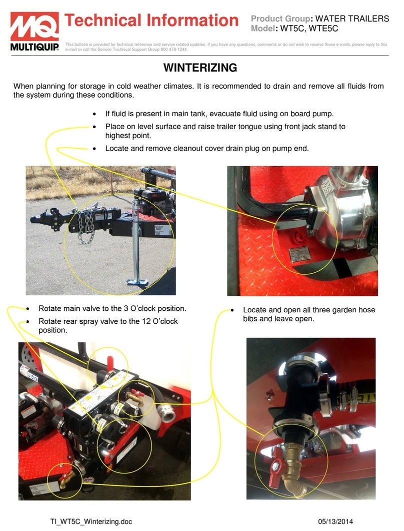
MULTIQUIP WT5C technical information
Cub Cadet
Cub Cadet J467 Operator's manual
Club Car
Club Car TURF 252 2007 Maintenance and service manual

Floe
Floe Cargo Max 650-70006-01 Assembly instructions
