Aussie Surveillance SPEED DOME Series User manual

SPEED DOME IP CAMERA
SERIES
OPERATION GUIDE

Please read instructions thoroughly before operation and retain it for future reference.
m2592L_LL_operation_V0.9
IMPORTANT SAFEGUARD
All lead-free products offered by the company comply with the requirements of the
European law on the Restriction of Hazardous Substances (RoHS) directive, which means
our manufacture processes and products are strictly “lead-free” and without the hazardous
substances cited in the directive.
The crossed-out wheeled bin mark symbolizes that within the European Union the product must
be collected separately at the product end-of-life. This applies to your product and any peripherals
marked with this symbol. Do not dispose of these products as unsorted
municipal waste. Contact your local dealer for procedures for recycling this equipment.
This apparatus is manufactured to comply with the radio interference requirements.
Federal Communications Commission Interference Statement
This equipment has been tested and found to comply with the limits for a Class B digital service, pursuant to
Part 15 of the FCC rules. These limits are designed to provide reasonable protection against harmful
interference in a residential installation.
Any changes or modifications made to this equipment may void the user’s authority to operate this equipment.
This equipment generates, uses, and can radiate radio frequency energy. If not installed and used in
accordance with the instructions, may cause harmful interference to radio communications. However, there is
no guarantee that interference will not occur in a particular installation. If this equipment does cause harmful
interference to radio or television reception, which can be determined by turning the equipment off and on, the
user is encouraged to try to correct the interference by one or more of the following measures:
Reorient or relocate the receiving antenna.
Increase the separation between the equipment and receiver.
Connect the equipment into an outlet on a circuit different from that to which the receiver is connected.
Consult the dealer or an experienced radio/TV technician for help.
FCC Caution: Any changes or modifications not expressly approved by the party responsible for
compliance could void the user's authority to operate this equipment.
All external cables connecting to this basic unit must be shielded.
For cables connecting to PCMCIA cards, see the option manual or installation instructions.
This device complies with Part 15 of the FCC Rules. Operation is subject to the following two conditions:
(1) This device mat not cause harmful interference, and
(2) This device must accept any interference received, including interference that may cause undesired
operation.
Trademark Acknowledgements
IOS is a trademark or registered trademark of Cisco in the U.S. and other countries and is used under license.
Android is a trademark of Google Inc. Use of this trademark is subject to Google Permissions.
Microsoft, Windows & Internet Explorer are registered trademarks of Microsoft Corporation in the United States
and/or other countries.
Disclaimer
We reserve the right to revise or remove any content in this manual at any time. We do not warrant or assume
any legal liability or responsibility for the accuracy, completeness, or usefulness of this manual. The content of
this manual is subject to change without notice.
This product doesn’t have a standby / off mode.

MPEG4 Licensing
THIS PRODUCT IS LICENSED UNDER THE MPEG4 VISUAL PATENT PORTFOLIO LICENSE FOR THE
PERSONAL AND NON-COMMERCIAL USE OF A CONSUMER FOR (i) ENCODING VIDEO IN
COMPLIANCE WITH THE MPEG4 VISUAL STANDARD (“MPEG-4 VIDEO”) AND/OR (ii) DECODING MPEG4
VIDEO THAT WAS ENCODED BY A CONSUMER ENGAGED IN A PERSONAL AND NON-COMMERCIAL
ACTIVITY AND/OR WAS OBTAINED FROM A VIDEO PROVIDER LICENSED BY MPEG LA TO PROVIDE
MPEG4 VIDEO. NO LICENSE IS GRANTED OR SHALL BE IMPLIED FOR ANY OTHER USE. ADDITIONAL
INFORMATION INCLUDING THAT RELATING TO PROMOTIONAL INTERNAL AND COMMERCIAL USES
AND LICENSING MAY BE OBTAINED FROM MPEG LA, LLC. SEE HTTP://WWW.MPEGLA.COM.
GPL Licensing
This product contains codes which are developed by Third-Party-Companies and which
are subject to the GNU General Public License (“GPL”) or the GNU Lesser Public License
(“LGPL”).
The GPL Code used in this product is released without warranty and is subject to the
copyright of the corresponding author.
Further source codes which are subject to the GPL-licenses are available upon request.
We are pleased to provide our modifications to the Linux Kernel, as well as a few new
commands, and some tools to get you into the code. The codes are provided on the FTP
site, and please download them from the following site or you can refer to your distributor:
http://download.dvrtw.com.tw/GPL/IPCAM/A-Seriers/linux.tar.gz

TABLE OF CONTENTS
1. OVERVIEW ......................................................................................................................................... 1
1.1 Product Features ....................................................................................................................................... 1
1.2 Package Content ....................................................................................................................................... 1
1.2 Cable Overview ......................................................................................................................................... 1
1.4 External Alarm Connection ........................................................................................................................ 2
1.5 Insert a Micro SD card............................................................................................................................... 2
2. CAMERA ACCESS WITH INTERNET EXPLORER ............................................................................ 3
2.1 Camera Login ............................................................................................................................................ 3
2.2 Control Panel Overview ............................................................................................................................ 3
2.2.1 Pan- / Tilt-Move Manually .................................................................................................................................
5
2.3 Digital PTZ (DPTZ) Operations ................................................................................................................. 5
2.4 Event Record Search & Playback ............................................................................................................. 6
3. CAMERA CONFIGURATIONS ............................................................................................................ 7
3.1 System configuration menu ....................................................................................................................... 7
3.2 Network ..................................................................................................................................................... 8
3.2.1 Network ............................................................................................................................................................ 8
3.2.2 QoS .................................................................................................................................................................. 8
3.2.3 DDNS ............................................................................................................................................................... 9
3.2.4 SNTP ................................................................................................................................................................ 9
3.2.5 FTP ...................................................................................................................................................................
9
3.2.6 MAIL ................................................................................................................................................................. 9
3.2.7 SMS ................................................................................................................................................................
10
3.2.8 Filter ............................................................................................................................................................... 11
3.2.9 UPnP / Bonjour ...............................................................................................................................................
11
3.2.10 RTP .............................................................................................................................................................. 12
3.2.11 IEEE 802.1X ................................................................................................................................................. 13
3.2.12 Network Share ............................................................................................................................................. 13
3.2.13 Network Failure Detection ............................................................................................................................ 14
3.3 Camera ................................................................................................................................................... 14
3.3.1 Camera ...........................................................................................................................................................
14
3.3.2 Preset ............................................................................................................................................................. 14
3.3.3 Cruise ............................................................................................................................................................. 15
3.3.4 Auto Tracking ................................................................................................................................................. 17
3.3.5 Video .............................................................................................................................................................. 17
3.3.6 ROI ................................................................................................................................................................. 18
3.3.7 Color ............................................................................................................................................................... 18
3.3.8 Audio .............................................................................................................................................................. 18
3.3.9 Advanced ........................................................................................................................................................
19
3.3.10 Home ............................................................................................................................................................ 20
3.4 VA ............................................................................................................................................................
20
3.4.1 TA ................................................................................................................................................................... 20
3.4.2 DIS ................................................................................................................................................................. 20
3.5 ONVIF ..................................................................................................................................................... 20
3.5.1 Event .............................................................................................................................................................. 20
3.6 Record..................................................................................................................................................... 21
3.6.1 Record ............................................................................................................................................................ 21
3.6.2 Record Timer ..................................................................................................................................................
21

3.7 Storage....................................................................................................................................................21
3.7.1 Memory .......................................................................................................................................................... 21
3.8 Trigger ..................................................................................................................................................... 22
3.8.1 Trigger ............................................................................................................................................................ 22
3.8.2 Snapshot ........................................................................................................................................................ 23
3.9 General ................................................................................................................................................... 24
3.9.1 General ...........................................................................................................................................................
24
3.9.2 Time ................................................................................................................................................................
24
3.9.3 Server Log ...................................................................................................................................................... 25
3.9.4 Online ............................................................................................................................................................. 25
3.9.5 Account ...........................................................................................................................................................
26
3.9.6 Google Maps .................................................................................................................................................. 27
3.9.7 Maintenance
................................................................................................................................................... 27
APPENDIX 1 BIT RATE TABLE FOR REFERENCE ............................................................................ 29
APPENDIX 2 RECORDING TIME TABLE ............................................................................................ 31
APPENDIX 3 API ID APPLICATION FOR SMS MESSAGING .............................................................. 32
APPENDIX 4 PRODUCT SPECIFICATIONS ........................................................................................ 34
Dimensions ................................................................................................................................................... 35
APPENDIX 5 PREREQUISITES FOR NETWORK SHARE .................................................................. 36
A5.1 Check PC IP Address ........................................................................................................................... 36
A5.2 Create "Administrator" Account ............................................................................................................. 36
A5.3 Share Folder ......................................................................................................................................... 37


1
1. OVERVIEW
1.1 Product Features
Quick network setup with your iOS® / Android™ mobile device
External alarm I/O device connection
-- For more accurate detection
-- Possible to enable active event notifications to your iOS® & Android™ mobile devices (Push Video) when used with Push
Video NVR series
ONVIF standard supported to simplify system integration
Auto Tracking to follow the moving object with the predefined surveillance area
IR effective range up to 200 meters or more when the IR Turbo mode is on
PTZ mechanism for wide and seamless surveillance
Hot Point support to quickly move the camera to a specific point remotely
Line in / out jacks available for audio transmission
POE (Power-over-Ethernet) support to eliminate the use of power cables and reduce installation costs
Capable of 360° pan rotation continuously and -3° ~ 90° tilt movement, allowing quick and smooth action of the camera lens
Remote Surveillance
-- Fully compatibility on iPhone & iPad, and Internet Explorer on Windows operating system - Free
PC program, CMS Lite, for 24CH devices monitoring on Windows operating system
1.2 Package Content
Standard Package
Camera Bracket Instructions Screw kit
CD manual Carabiner Terminal block Wretch
Optional Accessories
Waterproof kit
1.2 Cable Overview
Cable
Description
Power cable
Connect to the supplied adapter.
RJ45 network cable*
Connect to an Ethernet network cable.
BNC cable
No function.
Line-in
Colored as blue, used to connect to a microphone for audio input.
Line-out
Colored as green, used to connect to a speaker for audio output.
RESET
A wire reserved for hardware reset.

2
Terminal block
* For PoE (IEEE802.3af) installation, make sure your network cable has the maximum cable resistance of 20Ω, such as CAT.5e or CAT.6 cables, to conform to the
standard of IEEE802.3af.
1.4 External Alarm Connection
This camera supports external I/O device connection for easy connection.
Below shows you how to connect an external device to this camera.
1.5 Insert a Micro SD card
The data originally saved in the microSD card (if any) will be removed after inserting it to the camera.
The camera doesn’t support hot-swapping. Please insert or remove the microSD card with power disconnected.
Step 1: Remove the four screws. Then remove the plastic hull.
Step 2: After opening the camera hull, you can see the inner structure.
As the below illustration shows, insert the SD card face down into the slot.
Step 3: Replace the hull back, and make sure it’s fastened tightly to ensure the waterproof function works
properly.
Remove the insulating coating of the wire, and twist it with the GND wire together to reset
GND
the camera to ifs factory values.
1
. ALARM IN
Alarm input for an alarm device like magnetic contacts.
2
. ALARM OUT
Alarm output for an alarm device like a siren.
3
. GND
Ground wire
4
. RS485_A
Used for PTZ camera or other device connection.
5
. RS485_B
Used for PTZ camera or other device connection.

3
2. CAMERA ACCESS WITH INTERNET EXPLORER
This camera can be accessed via Microsoft®Internet Explorer®, and iOS®/ Android™ mobile devices with our self-
developed program “EagleEyes” installed depending on different using situations.
Note: For details about accessing this camera via iOS®/ Android™ mobile devices, please refer to
http://www.eagleeyescctv.com.
Before using the camera, make sure you have configured the network settings, and the network connection is fine.
For network configurations, please refer to “Advanced Network Setup” downloadable from www.surveillance-
download.com/user/m2592.swf.
2.1 Camera Login
Step1: Open your web browser, and key in http://ipaddress:portnum in the URL address box.
For example, for the IP address 60.121.46.236 and port No. 888, please key in ”http://60.121.46.236:888” into
the URL address box, and press “Enter”.
Step2: In the login page, key in the user name and password, and enter the security code from the image below if
any.
Then, click “LOGIN”.
Step3: The wizard is then started.
‧ To skip the wizard and directly access the camera live view, click “Close”.
‧ To directly access the camera live view without starting the wizard for the login next time, check “Do not start wizard at login”.
Note: If you’re prompted to install “VLC player”, “Software” or “H264 Streaming Viewer”, please agree
to proceed the installation. Or, you might not be able to see the live view properly.
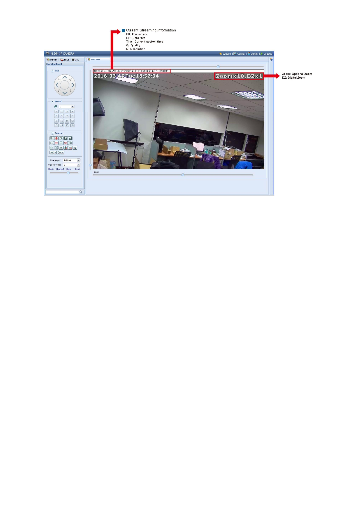
Step5: When the login is successful, the live view is shown.
2.2 Control Panel Overview
Note: The buttons available depend on the camera model you have, and the user level used to log in.
4
5
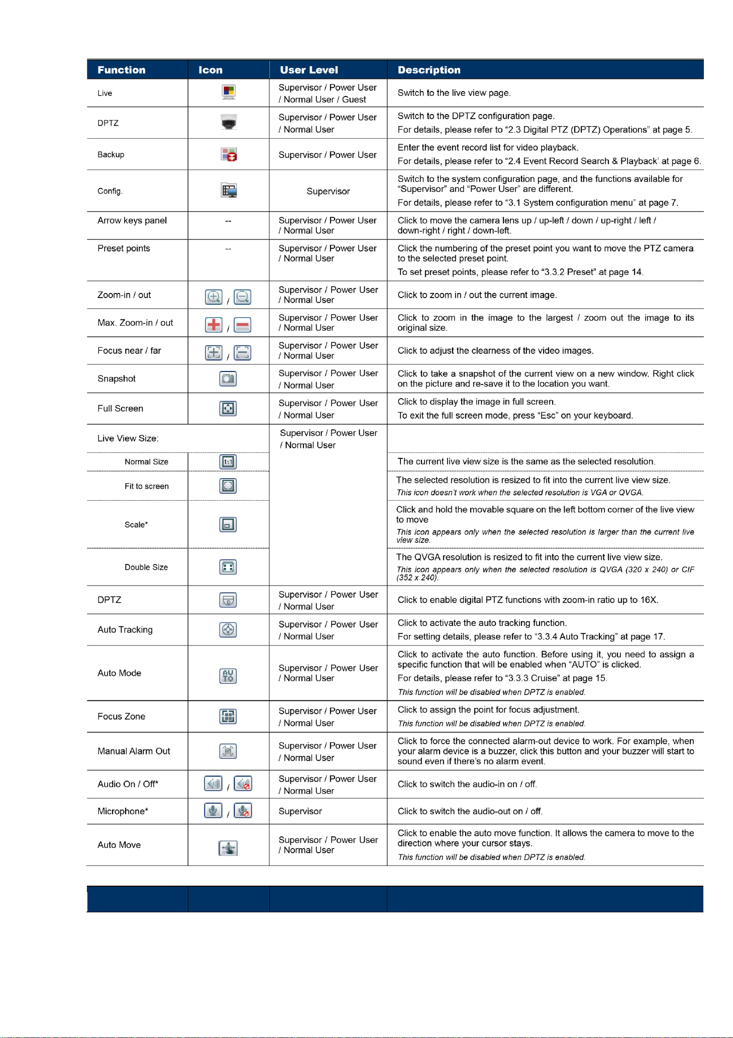
Function
Icon
User Level
Description
6
Live player
--
Supervisor / Power User
/ Normal User / Guest
Select the image player from the drop-down list:
ActiveX
QuickTime
QuickTime is Apple Inc.’s multimedia software. You need to have QuickTime
installed in your operating system before selecting “QuickTime”. When it is
selected, you will be promoted to enter the user name and password to access
the camera.
VLC
Video Profile
--
Supervisor / Power User
/ Normal User
Select the image resolution from the drop list:
1920 x 1080
720 x 480
1280 x 720
352 x 240
Quality
--
Supervisor / Power User
/ Normal User
Click & drag the slider to select the video quality:
Basic / Normal / High / Best.
2.2.1 Pan- / Tilt-Move Manually
There are three ways to manually move the camera view by:
Using the arrow key panel
Hot point –Directly click on the live view to move the camera view.
Using sliders –Click and drag sliders on the top and left side of the live view to move the camera view.
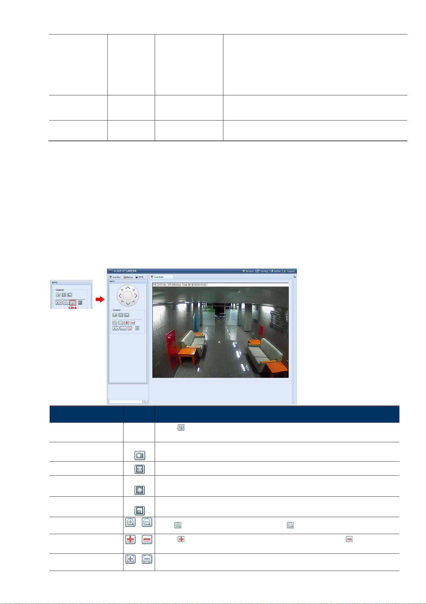
2.3 Digital PTZ (DPTZ) Operations
This camera series has PTZ capability, i.e. digital PTZ (hereafter called “DPTZ”), for wide area monitoring.
Click “DPTZ” on the top left corner to show the DPTZ control panel.
FUNCTION
ICON
DESCRIPTION
Moving panel
--
When is selected, the moving control panel will be shown to move the picture after zoom-in is
performed.
Take snapshots
Click to take a snapshot of the current view on a new window. Right click on the picture and re-save it
to the location you want.
Normal size
The current live view size is the same as the selected resolution.
Fit to screen
The selected resolution is resized to fit into the current live view size.
This icon doesn’t work when the selected resolution is VGA or QVGA.
Scale
Click and hold the movable square on the left bottom corner of the live view to move This
icon appears only when the selected resolution is larger than the current live view size.
Zoom in / out
Click once to enlarge the picture by 1X, and click once to restore the zoom ratio by 1X.
Max. zoom in / out
Click once to enlarge the picture to the max zoom ratio by 16X, and click once to restore
the picture ratio to 1X.
Focus near / far
Click to adjust the clearness of the video images.
/
/
/

7
Focus Zone
Click to assign the point for focus adjustment. This
function will be disabled when DPTZ is enabled.
2.4 Event Record Search & Playback
This camera can only save a few recordings.
Note: To save more recorded data, it’s recommended to use this camera with the compatible NVR.
Previous / Next Hour
Click to jump to the next / previous time interval in an hour, for example, 11:00 ~ 12:00 or 14:00
~ 15:00, and start playing the earliest event video clip recorded during this whole hour.
Fast Forward
Increase the speed for fast forward. Click to get 2X, 4X, 8X & 16X speed forward eventually.
Fast Rewind
Increase the speed for fast rewind. Click to get 2X, 4X, 8X & 16X speed rewind eventually.
Play
Click to play the current video clip.
Pause
Click to pause the video playback.
Stop
Click to stop the video playback.
Step
In the pause mode, click to get one frame forward.
Audio
Click to mute the playback if necessary, and click again to restore.
Download
Click to download the current video clip to the specified path in your PC.
The downloaded video can only be opened by our own video player. Please go to “General” →“Maintenance” to
download the video player, or get the player from the CD supplied with the sales package.
3. CAMERA CONFIGURATIONS
Users can further configure this camera by accessing via Internet Explorer.
3.1 System configuration menu
Click “Config.” to enter the configuration page.
Note: You need to be “Supervisor” to enter the system configuration page. If you’re not a “Supervisor”,
please re-log into the camera with the correct user name and password.
The functions are categorized into six menus: Network, Camera, Record Timer, Storage, Trigger and General.
/

8
For details about “Network”, please refer to “3.2 Network” at page 8. For details about “Camera”, please refer
to 3.3 Camera” at page 13.
For details about “VA”, please refer to “3.4 VA” at page 20.
For details about “Record”, please refer to “3.6 Record” at page 21.
For details about “Storage”, please refer to “3.7 Storage”’ at page 21.
For details about “Trigger”, please refer to “3.8 Trigger” at page 22.
For details about “General”, please refer to “3.9 General” at page 23.
Main Menu
Sub-Menu
Reference
Network
Network
Configure network settings.
QoS
Limit the data flow for live streaming.
DDNS
Enter DDNS information when the network type is PPPOE or DHCP.
SNTP
Synchronize your camera time with the networked computer systems.
FTP
Enter the FTP information for event notifications when “FTP” is chosen in “Trigger” →
“Trigger”.
Mail
Enter Email information for event notifications when “Email” is chosen in “Trigger” →“Trigger”.
SMS
Enter text messaging information for SMS notifications when “SMS” is chosen in “Trigger” →
“Trigger”.
Filter
Choose to permit or block the IP address(es) which can access this camera.
UpnP
*Suitable for Windows-based operating system.
Allow this camera to be detected among devices within the same network area for easy and
quick usage.
Bonjour
*Suitable for Apple Mac-based operating system.
Allow this camera to be detected among devices within the same network area for easy and
quick usage.
RTP
Set the parameters for video data transmission when you’re using multimedia other than web
browsers and Video Viewer for remote access.
IEEE 802.1X
The settings here enable the camera to access a network protected by 802.1X/EAPOL
(Extensible Authentication Protocol Over LAN).
Network Share
Assign a location in the LAN environment to save the snapshot of events when “Network
Share” is chosen in “Trigger” →“Snapshot”.
Network Failure Detection
Configure this camera to check the network connection of other device periodically, and send
notifications via Email or FTP for disconnection events.
Camera
Camera
1. Set the camera title.
2. Specify the display position of the camera title.
3. Specify where the snapshot files should be saved.
4. Configure the pan and tilt speed of the camera.
Preset
Set the preset points for the DPTZ function.
Cruise
Set the cruise mode when the auto mode is enabled: Sequence or Auto Pan.
Auto Tracking
Set the surveillance area for auto tracking, and the tracking timeout.
Video
Adjust video-related settings in different video format.
ROI
Select a specific area to reinforce the image quality of that area.
Color
Adjust the color performance.
Audio
Adjust the audio volume of the microphone and speaker.
Advanced
Adjust the camera parameters if necessary.
Home
Configure the camera to return to the specified point or specific cruise action when the camera
is not in use for a specific time.

9
Main Menu
Sub-Menu
Reference
VA
TA
This function should be used with the mini-guard control switch for alarm system integration.
For details, please check with your distributor or installer.
DIS
Enable this function to reduce blurring associated with the motion of a camera during
exposure.
ONVIF
Event
This function is used to integrate the functions of event and alarm detection when this camera
has to work with other ONVIF-compliant device.
Record
Record
Configure the record function.
Record Timer
Schedule the timer for automatic, external alarm and motion detection recording.
Storage
Memory
Check the current storage capacity and clear all recorded data when needed.
Trigger
Trigger
1. Enable / disable motion and alarm detection.
2. Set the motion detection area.
3. Configure how the camera reacts for any event.
Snapshot
Schedule the camera to take snapshots periodically or at a specific time, and send to E-Mail,
FTP and / or Network Share for backup. Time-lapse recording could also be configured here.
General
General
1. Select the language of the web browser.
2. Check the MAC address of the camera.
3. Lock camera access after the specified time.
Time
Set daylight saving time and the current time.
Server Log
Check the system event logs.
Online
Check the current online user(s).
Account
1. Create a new user account with different access privilege.
2. Modify or delete an existing user account.
Google Maps
Allow you to know where the camera is.
Maintenance
1. Check the current firmware version and upgrade your camera.
2. Copy system configurations.
3. Reboot the camera.
4. Download the video player to play the recorded data.
3.2 Network
3.2.1 Network
You can set the network configuration of the camera depending on your network type.
For details, please refer to “Advanced Network Setup” from www.surveillance-download.com/user/m2592.swf.
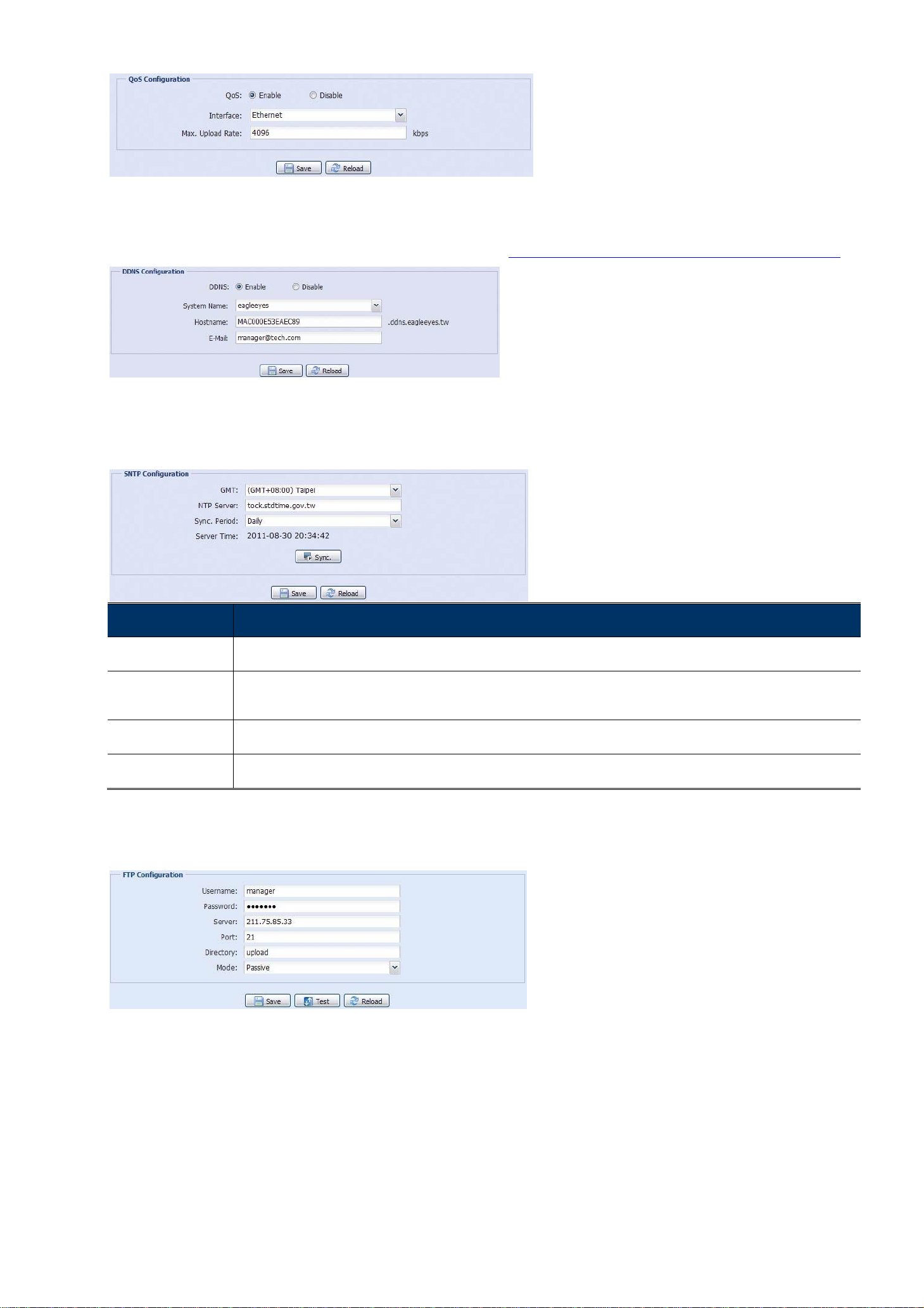
3.2.2 QoS
QoS, Quality of Service, is the ability to control the data flow for real-time streaming. This function is important if
your network bandwidth is insufficient and you have other devices to share the network bandwidth.
Check “QoS Enable”, and set the max. upload rate from 256 to 10240 kbps.
10
3.2.3 DDNS
Select “On” when the selected network type in “Network” is “PPPOE” or “DHCP”.
For details, please refer to “Advanced Network Setup” from www.surveillance-download.com/user/m2592.swf.
3.2.4 SNTP
SNTP (Simple Network Time Protocol) is used to synchronize your camera time with the networked computer
systems.
Function
Description
GMT
Once users choose the time zone, the camera will adjust the local area time of the system automatically.
NTP Server
Simply use the default SNTP server (For example, tock.stdtime.gov.tw) or change to another server with which users are
familiar.
Sync. Period
Select “Daily” to synchronize the camera time with the network time every day or “None” to turn off this function.
Sync
Click and the camera will synchronize the time with the network time.
3.2.5 FTP
Enter the detailed FTP information and click “Save” to confirm. The information you set here will be applied when
“FTP” is selected in “Trigger” →“Trigger”.
3.2.6 MAIL
Enter the detailed e-mail information and click “Save” to confirm. The information you set here will be applied
when “Email” is selected in “Trigger” →“Trigger”.

11
Function
Description
SMTP Server
Enter the SMTP server address provided from your e-mail system supplier.
Port
Enter the port number provided from your e-mail system supplier. If this column is left blank, the e-mail server will use
port 25 to send e-mails.
Mail From
Enter the name of the sender.
SSL Encryption
Select “Yes” if your e-mail server is using SSL encryption to protect your e-mail content from unauthorized access.
Verify Password
Some mail servers are required to verify the password. Please enter the “user name” and “password”.
Subject
Enter the subject for the E-Mail.
E-Mail Address
List
Add the e-mail address(s) of the assigned recipient(s).
Test
When all information is entered, click “Test Mail” to try if the receipt.
3.2.7 SMS
Note: Before using this function, you need to apply an account and get an API ID from the mobile
messaging company, such as Clickatell and EVERY8D.
For details, please refer to “APPENDIX 3 API ID APPLICATION FOR SMS MESSAGING” at page 32.
Enter the detailed information needed for text messaging, and click “Save” to confirm. The information you set
here will be applied when “SMS” is selected in “General” →"Trigger".
Function
Description
System
The text messaging service provider is Clickatell.
User name / Password
Enter the account user name and password you created in Clickatell.
API ID
Enter the API ID you applied from Clickatell.
12
Recipient
Click “Add” to enter the phone number, including the country code, to receive the text
message. Five sets of phone numbers are allowed.
Transfer Interval
Set the interval time in minutes between two-message sending. The
options are 0, 15, 30 & 60.
Reset Counter
Click to restart the text messaging, and the SMS will be sent after the specified time interval
since you click this button.
Message
Enter the text content (up to 70 characters) you want to send with the text message.
Test
To know whether your SMS setting is correct, click this button to immediately send a SMS to
your phone.
Note: This testing is not free and you will be charged for SMS sending base on your
local rate.
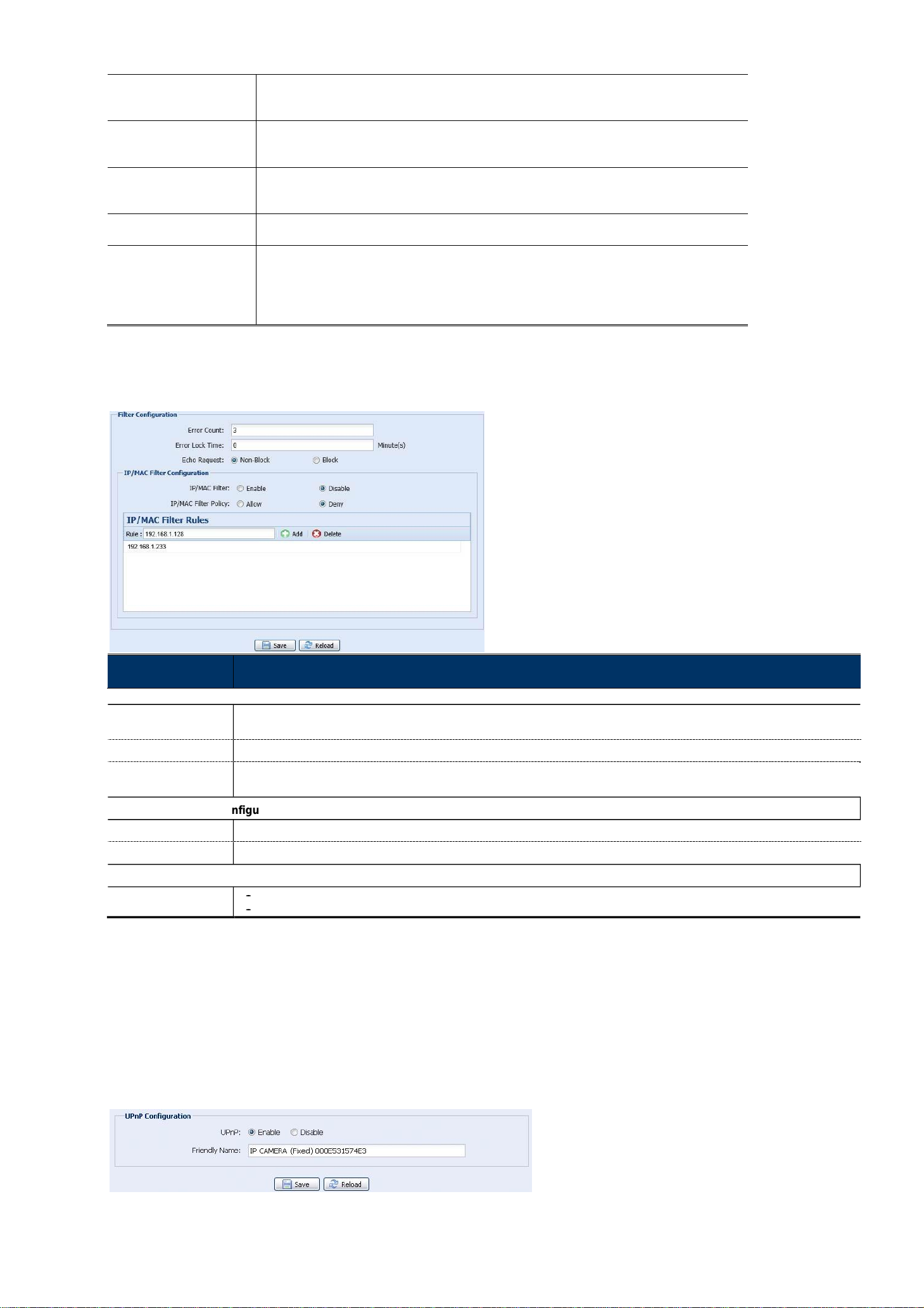
3.2.8 Filter
Choose to permit or block the IP address(es) which can access this camera, and click “Save” to confirm.
Function
Description
3.2.9 UPnP / Bonjour
“UPnP” stands for “Universal Plug and Play”, which allows devices to connect seamlessly in the home and
corporate environments and simplify installation of computer components, and is only suitable for Microsoft
Windows-based operating system.
“Bonjour” functions the same as “UPnP”, but it’s only suitable for Apple Mac-based operating system.
UPnP
Bonjour
Filter Configuration
Set the maximum count for login failure. When the maximum count is reached, the IP address trying to access the
Error Count
camera will be locked.
Set the lock time in minutes when the maximum count of error login for an IP address is reached.
Error Lock Time
Select “Non-Block” to allow other users to use the ping command to detect the IP address of your camera, or “Block” to
Echo Request
deny the ping command request.
nfiguration
IP/MAC Filter Co
IP/MAC Filter
Choose to enable or disable the filter function.
IP/MAC Filter Policy
If “Enable” is selected, choose whether you want to permit (Allow) or block (Deny) the IP address list below.
IP/MAC Filter Ru
les
Rule
To add an item to the IP address list, key in the IP address in “Rule”, and click “Add”.
To remove an existing item in the IP address list, click the item you want to remove, and click “Delete”.

13
Check “Enable” to allow the camera to be detected among devices within the same network area, and set the
identification name of the camera in “Friendly name”.
When this function is activated, the other PC within the same domain as this camera will be able to search this
camera in:
“Network Neighbor” with the identification name set in “Friendly name” for Windows-based PC, or “ ” (finder)
or “Bookmark” with the identification name set in “Device Name” for Mac-based PC.
Double-click it to quickly open the web browser for camera access.
Port Mapping (Available only in UPnP)
This function can eliminate the need to additionally access the router for port forwarding.
For details, please refer to “Advanced Network Setup” from www.surveillance-download.com/user/m2592.swf.
Note: Before using this function, make sure your router supports UPnP, and this function is enabled. If
not, please access your router additionally for port forwarding.
When “Port Mapping” is set to “Enable”, the system will automatically assign an IP address or port number for
you if no IP address or port number is entered.
Note: When the configurations are saved successfully, you’ll see a message indicating the IP address
and port number assigned to this camera.
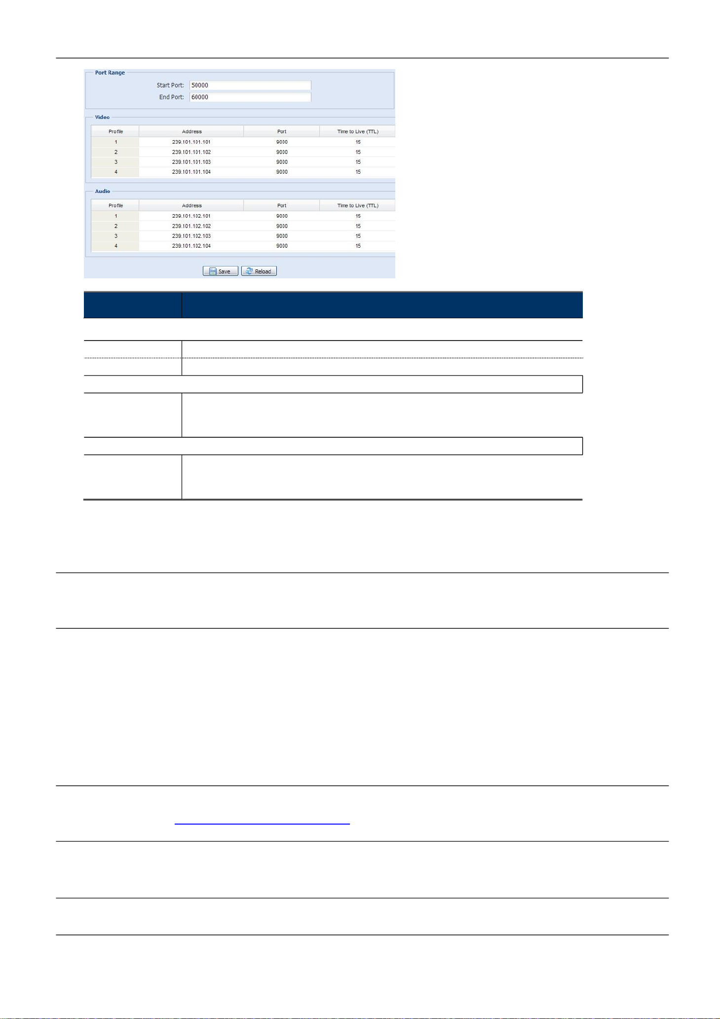
3.2.10 RTP
The Real-time Transport Protocol (RTP) is an Internet protocol standard to manage the real-time transmission of
multimedia, such as VLC player.
The media player you want to use for remote access must support RTP transmission for this function to work
normally.
Note: When you’re about to end the remote access, please press the stop button on your media player
first, and then close the program. This is to ensure the server receives the stop command, and
also help to protect the server from redundant data transmission.
14
Function
Description
Port Range
The port range used by RTP is limited, and preserving 100 ports between the start port and end port is necessary.
3.2.11 IEEE 802.1X
The settings here enable the camera to access a network protected by 802.1X/EAPOL (Extensible
Authentication Protocol Over LAN).
Note: For authentication to work properly, it's important to synchronize the time in the camera with an
NTP server.
Before using this function, make sure:
The switch and RADIUS server you have in the LAN environment supports IEEE 802.1X, and IEEE 802.1X
settings are enabled.
You’ve applied a digital certificate from a Certificate Authority which can be validated by a RADIUS server,
and the identity and password used.
Then, follow the steps below:
Step1: Connect this camera to a PC or laptop directly, and go to its login page to log in.
Note: To know how to connect the camera to a PC or laptop directly, please check “4 Modem / Hub +
Modem” in “ADVANCED NETWORK SETUP”.
Step2: Log into the camera, and go to “Config” “Network” “IEEE 802.1X”. Enable this function, and select
the EAP method you want to use.
Note: This camera supports “EAP-PEAP”, “EAP-TLS” and “EAP-TTLS”.
Step3: Enter the identity and password you get from the Certificate Authority, and select the EAPOL version used
in your switch.
The range of the start port is 1024 ~ 65434.
Start Port
The range of the end port is 1124 ~ 65534.
End Port
Video
Address and port for
video transmission
Set a specific address and port for multicast of profile 1 ~ 4.
The range of the address is limited between 224.0.0.1 ~ 239.255.255.255.
The port for multicast must be an even number.
Audio
Address and port for
audio transmission
Set a specific address and port for multicast of audio.
The range of the address is limited between 224.0.0.1 ~ 239.255.255.255.
The port for multicast must be an even number.
This manual suits for next models
1
Table of contents


