AUSTHEAT AHT860 User manual
Instruction Manual
FREESTANDING ELECTRICAL HOTPLATE & TOASTER
AHT860
Version 5

2
CONTENTS
Product Features 2
Specifications 2
Parts Included 2
Safety Instructions 2
Cleaning & Maintenance 3
Installation 3
Electrical Connection 4
General Information 4
Control Layout 5
Cooking/Heating Zones 5
Operation 6
Workstation Layout 6
Safety 7
Troubleshooting 7
Thermal Cut-outs 9
Compliance 8
Spare Parts 9
Circuit Diagram 10
Exploded Views Error!
Bookmark not defined.1
Warranty 17
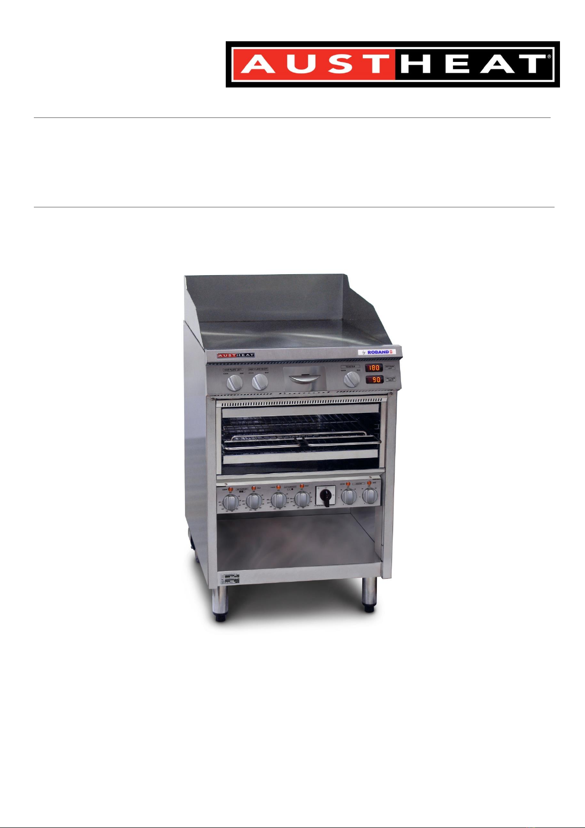
PRODUCT FEATURES
High Temperature Capacity
Durable Stainless Steel Elements
12mm Steel Hotplate
Adjustable Legs & Rear Castors
Easy Cleaning Grease Over-Spill Box
Digital LED Temperature Display
Independently Controlled Grill
Cook/Idle Selector Switches
SPECIFICATIONS
Model
Power
(400VAC)
Size (mm)
Kg
W
D
H
AHT860
12.5KW
590
855
1075
120
PARTS INCLUDED
Electrical Hotplate & Toaster (AHT860)
Instruction Manual
Any damage to the machine as a result of
freight must be reported to the Freight
Company and to the agent responsible for the
despatch of machine within 24 hours of receipt.
No claims will be accepted after this period.
SAFETY INSTRUCTIONS
Read all Instructions and safety warnings prior to
use. Keep user manual for future reference.
Service and repair should only be performed by
qualified technicians who have read and
understood this manual.
Personnel must be trained prior to operating
this appliance.
This product is suitable for commercial use only.
This machine should not be operated by
persons (including children) with reduced
physical, sensory or mental capabilities, or lack
of experience or knowledge, unless they have
been given supervision or instruction concerning
the safe use of the appliance by a person
responsible for their safety.
Keep out of reach from children.
Avoid contact with the exterior of this machine
as surfaces can get hot.
Do not position appliances where hot surfaces
may be accidently touched.
The machine should be disconnected from all
power and allowed to cool before cleaning or
servicing.
Regularly inspect the supply cord/plug and
discontinue use immediately if damage is found.

3
Return to manufacturer or authorised repairer
for repair prior to use.
This machine contains no user-serviceable parts.
Austheat®, one of our agents, or a similarly
qualified person(s) should carry out repairs.
Keep cord away from heated surfaces.
Do not remove any cover panels from the
machine.
Austheat® will not accept liability if:
Non-authorised personnel have tampered
with the machine
The instructions in this manual have not
been followed
Non-original spare parts are used
There is any damage to the unit
These units should NOT be left unattended
during operation.
During use, these units heat up and can cause
damage or bodily harm if not operated
correctly. Ensure proper signage is in place to
reduce the risk of any hazards.
CLEANING & MAINTENANCE
Switch off at mains switch and allow to cool
before cleaning.
CAUTION: Steel cutting processes used in the
construction of this machine can result in sharp
edges. Avoid contact with sharp edges during
cleaning and maintenance.
Do not clean with the use of a water jet or
immerse in water.
Do not use caustic or abrasive cleaning products
as they will damage the machine.
Empty/clean grease box regularly
Regular cleaning will prevent a build-up of oils
and keep the machine looking new.
No part of this machine (with the exception of
the grease box) should be immersed in water.
Wipe all surfaces of the machine with warm
soapy water using a damp non-abrasive cloth.
WARNING: Some cleaning agents can damage
stainless steel or the polycarbonates/plastics
used in switches and pilot lights. Only ever use
soapy water as a cleaning agent.
Ensure the unit is switched off before any
servicing or inspection is carried out.
Servicing and maintenance should only be
carried out by a qualified technician. It is
recommended that inspections be carried out
annually to ensure the appliance is in line with
changing standards.
INSTALLATION
Remove all packaging materials, tape, and any
protective plastic from the machine. Remove
any glue residue from the protective plastic or
tape using citrus cleaner.
Place the product on a firm, level surface in the
desired position. Do not install within 300mm of
flammable materials. The AH860 has a rear
spacer to set a minimum distance from non-
flammable walls that must never be removed or
modified.
A minimum distance of 500mm above the
cooking plate must be kept clear of any
obstruction. Do not obstruct or in any way close
off the front of the machine.
Install at least 100mm from materials and have a
100mm air gap at the front & rear of the unit. If
the unit is used near combustible material,
common sense should be applied to deem
sufficient distancing.
Consult national standards that outline the
positioning, spacing and ventilation before
installation.

4
If this appliance is located in a row of appliances
(e.g. Austheat® Fryer), ensure that adjacent
machines do not restrict air flow. Failure to
provide adequate air flow could result in the
tripping of the thermal protective circuits within
the unit.
Consideration should be given to securing the
unit or limiting mobility if the unit is hard-wired.
Consult appropriate standards to ensure
compliance with all requirements.
We recommend the use of an RCD (Residual
Current Device) rated at no less than 30mA for
circuit protection. If an RCD is used to protect
multiple appliances, ensure the RDC is
appropriately rated so as to allow up to 30mA
leakage current for this unit.
CAUTION: Do not attach any other items,
machines or brackets to these units as any such
alterations may change the thermal properties
or safety aspects of these machines and will void
any warranty.
CAUTION: In order to avoid inadvertent re-
setting of the internal thermal cut-outs, ensure
the appliance is not wired through an external
switching devices (such as a timer), or any device
that is regularly switched on and off by the
utility.
ELECTRICAL CONNECTION
Before connecting the machine to the power
supply, ensure that all switches are in the OFF
position.
A licensed electrician must install this unit to
comply with national installation codes and
regulations. Means for disconnection from
supply must be incorporated in the fixed wiring
in accordance with the wiring rules.
WARNING: UNIT MUST BE EARTHED
We also advise that this unit, and any other
stationary appliances, be connected to a
equipotential bonding grid to eliminate any
differences in electrical potential within the
kitchen,
WARNING: If the electrical mains supply cabling
is damaged, the machine must not be used until
a qualified person has replaced the cabling and
deemed the machine to be functioning properly.
There are two main supply connection points in
the unit. The first is through the lower back
panel at the rear of the unit. The second
connection point is through the base of the
machine at the rear. Both connection points
have three choices of holes for the cable to pass
through. Protection must be given to the mains
cables if they are positioned such that they can
contact the hot surfaces of the unit. A suitable
cable gland is required for the cable to pass
through.
Each hotplate must be connected to an
adequately protected power supply and an
isolation switch mounted adjacent to, but not
behind the Hotplate. This switch must be clearly
marked and readily accessible in case of fire.
GENERAL INFORMATION
This appliance is designed as a floor mounted
unit. The controls are located along the front
display panel with the primary ON/OFF switch
located on the lower control panel.
These units generate an extreme amount of
heat, which has the capacity to adversely affect
some components within the machine. To
prevent any damage, and to provide an air
curtain along the grease box guide assembly
and upper display panel, these units are fitted
with internal fans.
In the event of a failure of an internal fan, a
safety thermostat will operate and cut power to
the machine, the result being a sudden loss of
power (pilot lights will no longer be lit).
If such a shutdown occurs, leave the unit to cool
for 30 minutes and turn the unit off and back on.

5
This electrical reset will allow the unit to begin
operating again. If the unit shuts down a
second time this is confirmation that the unit is
overheating and you should call Austheat®or
your local electrician for service.
A strong Pest-Eradication program should be in
place in any kitchen before installing this or any
similar machines.
WARNING: Pouring cold water onto a hot plate
will cause spitting and may result in damage to
the plate.
If required, the unit can be moved by lifting
from underneath the front, just above the door,
and pulling it along on the rear castors.
CONTROL LAYOUT
WARNING: THE ON/OFF SWITCH DOES NOT PROVIDE COMPLETE ISOLATION –REFER TO
“ELECTRICAL CONNECTION”.
CONTROL DESCRIPTION
Both the hotplate and toaster have an idle/cook function, meaning you are able to have 2 pre-set
temperatures to switch between. Simply set the thermostats on the lower control panel to your desired
cooking or idle (non-peak cooking period) temperatures and switch between the two during busy
periods (or quiet periods) to save energy.
TOP DISPLAY PANEL CONTROLS
Cook/Idle
switch –Left
Heating Zone
Cook/Idle
switch –Right
Heating Zone
Cook/Idle
switch –
Toaster
Thermometer
Displays
Lower Control Panel
Left Zone
Thermostats
Right Zone
Thermostats
On/Off
Switch
Toaster Controls
Grease Tray
6
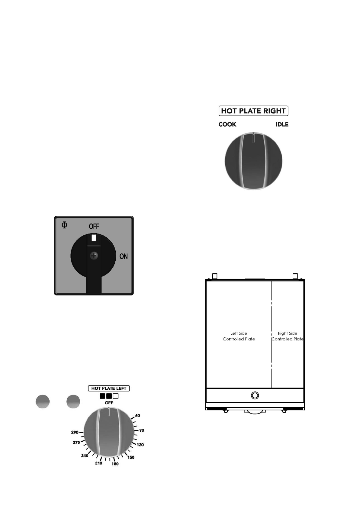
CONTROL DESCRIPTION
This appliance utilises a hotplate that is able to
heat either the left side, right side or both sides
during operation. The three elements heating
the hotplate are split so that the left thermostat
controls the 2 left elements, and the right
thermostat controls the element on the right
hand side.
Both thermostats have a maximum temperature
of 290C as seen below.
The primary ON/OFF switch is located on the
lower control panel which, when turned in the
“ON” position, will illuminate the green pilot
light located on the upper display panel and
signal that the unit is operational.
While the green pilot light will be constantly
illuminated during operation of this appliance,
the 2 orange pilot lights connected to either the
left or right hand side controls will cycle on/off
as the thermostat supplies power to the
elements to maintain the predetermined
temperature.
The Cook/Idle Switch allows you to quickly
switch between 2 predetermined temperatures
set by the lower thermostat.
Each thermostat clearly labels which operating
“zone” it controls, and matches up with the
relevant Cook/Idle Switch.
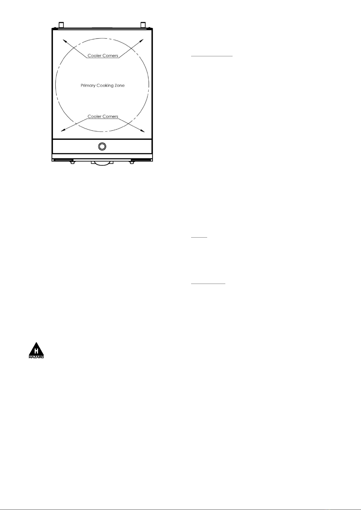
COOKING/HEATING ZONES
As previously mentioned, the hotplate is not
split evenly, with the left hand side elements
heating 2/3rd of the hotplate and the right hand
side elements heating the remaining 1/3rd (as
seen in the pictorial below).
The hotplate is designed in such a way that heat
pools in the centre of the hotplate, with the
front and rear corners being comparatively
cooler. This allows the user to balance the
cooking times of multiple products/foods that
require different temperatures or times to cook.
7
TOASTING CONTROLS
The toaster element is controlled by the two
energy regulators on the lower control panel on
the right hand side. These are wired to a
“Cook/Idle” switch on the upper display panel
which allows switching between the two energy
regulators.
It is suggested that the “Cook” energy regulator
be set between 4-HIGH, and that the “Idle”
energy regulator be set to 2. This will allow the
elements to stay warm while using minimal
power and will speed up the recovery time
when the “Cook” setting is later selected. This is
only a guide and only personal use will dictate
the best settings for your particular bread.
Always use gloves when handling the
toast rack during operation.
TEMPERATURE DISPLAY
The temperature displays can be seen on the
display panel, located on the front of the
hotplate on the right hand side. It displays the
current approximate temperature if the
appropriate hotplate “heating zone”.
In the event of an overheating situation, the
temperature displays will also be shut down and
will not re-illuminate until the machine is turned
off and back on again (after cooling down).
OPERATION
SEASONING
Before cooking for the
first time
the hotplate
need to be seasoned as follows.
Remove the paper from the plate and wipe
off excess fat.
Brush the plate liberally with frying oil and
cover the surface with a layer of salt.
Set the thermostat to a temperature of
around 180and heat for 25 minutes.
Allow the oil and salt to cool, and then
remove it carefully without scratching the
surface.
Brush the plate with oil again and re-heat
until the oil is burnt in. This will form a skin
on the surface of the plate.
Re-oil the surface once again.
Your Hot Plate is now ready for use. Be sure to
never clean the hotplate using cleaning agents
(only soapy water) as this can strip back the
seasoning layer that has formed and can
damage the plate.
COOKING
1. Rotate the main switch to the “ON” position,
the green pilot light will illuminate, indicating
power is on.
2. Rotate thermostats to desired cooking/idle
temperature. Once set, the amber pilot light
associated with each side will illuminate until the
temperature is reached and will turn off.
3. Once the amber pilot light switches off,
cooking may commence (temperature has been
reached). Notice the amber pilot light will cycle
on/off in sync with when the thermostat
energises the elements.
4. When finished with the appliance, ensure
both thermostats are set at “OFF” and primary
switch is in the “OFF” position.

8
TOASTING
WORKSATION LAYOUT
These units are likely to be installed next to
similar sized machines (e.g. Fryers) that will
perform complimentary roles. In most cases,
operators will be using this machine in
conjunction with a bench or suitable surface on
which burgers and other food products can be
assembled or prepared.
For this reason, we recommend that areas
between this unit and other machines and work-
surfaces be kept clear of any potential obstacle
or trip hazard. Work areas should also be
cleaned and floors should be oil-free to reduce
the likelihood of slipping.
It is anticipated that these machines will be
operating beneath a suitable exhaust/extraction
unit to reduce the ambient temperatures around
the operator.
SAFETY
GENERAL SAFETY
This machine contains no user-serviceable parts.
Austheat®Australia, one of our agents, or a
similarly qualified person(s) should carry out all
repairs. Any repair person(s) should be
instructed to read the safety warnings within this
manual before commencing work on these
units.
Steel cutting processes such as those
used in the construction of this machine
result in sharp edges. Whilst any such edges are
removed to the best of our ability it is always
wise to take care when contacting any edge.
Do not remove any cover panels that may
be on the machine (with the exception of
the circuit breaker cover.
This unit can get very hot, ensure everyone is
aware that the machine is operating and take
care to avoid contact with hot surfaces. (Refer to
installation for guide to ventilation)
Always ensure the power cable is not in contact
with hot parts of the machine when in use, and
ensure that if the cable is damaged in any way
that it is replaced immediately
Always use original spare parts. Genuine
Austheat®parts have been checked for
compliance and reliability and the use of non-
original spare parts may compromise the
function or safety of these units.
As part of the normal operation of this unit, hot
air is expelled out the front of the unit. Never
block or interfere with this air flow as the internal
temperatures may rise and component damage
can occur.
GENERAL FIRE SAFETY
Before using any hotplate adequate safety
measures should be in place. Such measures
should include, but not be limited to, having an
appropriate fire extinguisher or fire blanket
located nearby in case cooking oils on the plate
ignite. Refer to the appropriate regulations
pertaining to your operating environment for
details of the correct fire prevention measures
required.
SAFETY OF SERVICEPERSONS
Before servicing this machine it is necessary to
disconnect all power. These units are NOT
fitted with a mains isolating switch –as detailed
in the installation section of this manual, an all-
pole disconnection isolating switch should be
mounted and wired
external
to this machine. A
cooling circuit will remain “live” within these
units even when turned “off” at the control
panel. Please consider this before allowing
qualified servicepersons to gain access to the
machine.

9
TROUBLESHOOTING
If the Hotplate does not function check the
following points before calling for service.
The power is switched “on”, both on the
unit and at any other point that supplies
power to the machine (e.g. an isolating
switch on the wall).
The mains power is not faulty.
The temperature has been set correctly and
the thermal cut-out has not tripped. Refer to
the “Thermal Cut-Out” section previous for
more information on this control.
The thermostat knobs are not loose or
broken, rendering the thermostats
inoperable.
The circuit breakers located inside the lower
section of the unit are all in the “on”
position”. These are located behind a cover
panel.
Typical issues that can be easily identified can
be listed below:
1.1 Symptom –All power shut off
1.2 Check –Is air still flowing through the grease
box guide?
1.3 Probable Cause –(If Yes) –Overtemp has
cut out. Let machine cool for 30 minutes before
switching back on. (If no) –Possible failure of
primary fan or ON/OFF switch
2.1 Symptom –Plate takes too long to
heat/cook
2.2 Check –All circuit breakers are in the “ON’
position
2.3 Probable Cause –If tripped, there could be
possible element failure. Reset circuit breakers
and operate as normal. Call for service if they
trip again.
3.1 Symptom –Grinding noise coming from
inside the unit
3.2 Check –Does it sound like a fan turning but
being noisy?
3.3 Probable Cause –Internal fan bearing may
be failing. Call for servicing before the fan fails,
as such a failure will cause the machine to
overheat and shut down.
THERMAL CUTOUTS
These units are fitted with an internal safety
thermostat designed to cut power if the internal
temperatures reach a point where other
components may be damaged. There are a
number of possible situations that may cause
the safety thermostat to cut out, such as a
thermostat failure or the failure of an internal
fan. You may follow the procedure below as a
first step to rectifying the problem.
1. Switch the Hotplate OFF using the main
On/Off switch and allow it to cool for
approximately 30 minutes.
2. Switch the unit back on –operation can
now continue as normal.
3. Repeat steps 1 and 2.
4. If the unit again trips out it may be the
result of a failure in an internal fan -
phone for service.
If the Hotplate continues to perform without any
further tripping of the thermal cut-out after step
3, then there is a strong possibility that the
thermostat in use at the time is faulty, or that
one of the internal cooling fans is no longer
functioning. This should be attended to by
qualified electrical personnel.
If the machines have tripped the thermal cut-out
two or three times switch the unit off and refrain
from further use until the unit has been repaired.
Continuing to use the machine may cause
premature failure of other components if
repeatedly exposed to over-temperature
situations.

10
COMPLIANCE
RCM:
Austheat®products have been designed and
manufactured to comply with any and all
specifications set out by the Australian
Communications and Media Authority (ACMA)
in regards to Electromagnetic Compatibility. As
testament to such compliance these units bear
the RCM symbol.
For further information contact the Australian
Communications Authority, PO Box 13112, Law
Courts, Melbourne VIC 8010.
ACSS (Advance Control Safety System)
The ACSS framework is a stringent and specific
set of voluntary requirements aimed at the
electrical safety, reliability and longevity of
equipment used in the foodservice industry.
The ACSS framework has been developed as
both a guide to the engineering and
development of products as well as a guarantee
to consumers that Austheat®equipment bearing
this mark not only meets the requirements of the
Australian Standards, they exceed them.
A unit bearing the ACSS mark is your guarantee
that you are purchasing a machine built to far
exceed the Australian standards. The unit has
been designed to be safer, particularly from an
electrical aspect, and last longer than similar
units on the market today.
SPARE PARTS
EC0225 Circuit Breaker –32A
ES0232 Mains Rotary Switch –4 Pole
EC0245 Rail Mounted Terminal Block Red
EC0246 Rail Mounted Terminal Block
Blue
EC0247 Rail Mounted Terminal Block
Earth
EC0249 Bridging Link
EC0347 Circuit Breaker –13A
EC0348 Contactor –2 Pole –25A
EC0361 Contactor –1 Pole –25A
EC0471 Fan –Tangential –18W
ES0264 Amber Pilot Light Assembly
ES0265 Green Pilot Light Assembly
HC0141 Element –125W 230VAC
HC0174 Element –3500W 230VAC
MC0093 Clamp - Cable
MC0609 Adjustable Leg
MC0610 Castor
MC0649 Toasting Rack
PC0276 Bush –1 3/8” Nylon 6/6
PC0287 3/4” Plastic Knockout Plug
PC0288 1” Plastic Knockout Plug
PC0379 Bush –1 3/8” Nylon 6/6 –
Slotted Face
SS2204 Crumb Tray/Reflector
SS2219 Circuit Breaker Cover
TC0033 Thermal Cutout - 60C –N/O
TC0035 Thermal Cutout - 70C –N/C
TS0030 Thermostat 290C Pan Assembly
VS0374 Grease Box & Handle Complete

CIRCUIT DIAGRAM

12
WARRANTY
© Copyright 2021 –Roband® Australia Pty Ltd
All rights reserved. No part of this work may be reproduced or copied in any form or by any means,
electronic or mechanical, including photocopying or posting to a website, without the written permission of
the publisher. The material contained within this document is intended entirely for instructional purposes.
Roband®Australia is a wholly Australian owned company and has been manufacturing quality commercial
catering equipment for the food service industry for more than 60 years.
This manual suits for next models
1
Table of contents
Popular Cooktop manuals by other brands


Miele
Miele KM 611 Series Operating and installation instructions

LG
LG MFL62725501 installation instructions

Jenn-Air
Jenn-Air JED8130ADB Use & care guide

Thor Kitchen
Thor Kitchen TGC Series manual

Monogram
Monogram 36 Ceramic Cooktop installation instructions

Jenn-Air
Jenn-Air CCE3401 installation instructions

Aarow
Aarow BK061 Operating & installation manual

Fisher & Paykel
Fisher & Paykel CG363MLNGB1 instructions

True Induction
True Induction TI-2B user manual

AIRLUX
AIRLUX TV267MC RECOMMANDATIONS DE MONTAGE ET MODE D’EMPLOI

Gaggenau
Gaggenau VI 414 613 use and care manual

Linea 2000
Linea 2000 DOMO DO-309KP Instruction booklet