Austin AUSTINDRIVE User manual

AUSTINDRIVE Assembly Tutorial Rev 3.02 December, 2020
1
AUSTINDRIVE PEDAL
DIY PROJECTS

AUSTINDRIVE Assembly Tutorial Rev 3.02 December, 2020
2
QUICK START GUIDE:
(These links skip-over some of the explanation, and get right to the instructions.)
1. Tools and Preparation
2. Circuit Design
3. Drill the Enclosure (Some models only)
4. Apply the Graphics
5. Stuff and Solder the Printed Circuit Board (“PCB”)
6. Wire the Jacks and Switches
7. Wire the Enclosure
8. Create Your Tone
9. Troubleshooting Problems
This is a true DIY Pedal, designed to introduce some concepts of circuit design, and help people become
curious about building their own equipment.
Release of Liability Notification - Please Read This:
You will be soldering, using a sharp razor blade, scissors, cutting and stripping wires, and in some cases,
drilling the metal enclosure. There are dangers involved - based solely on the tools you are choosing to
use, and your experience using them. This is not a learning manual for using these tools. Avoid breathing
fumes from your solder, flux or paint, and try to use lead-free (“RoHS”) solder whenever possible.
Personal Protective Equipment (PPE) is a MUST for this project.
Do not take risks that could cause injury –especially to your eyes or hands –while building this pedal.
Your fingers can be permanently damaged from heat or sharp objects, and that’s not good for a guitar
player. Don’t “feel if this is sharp” by running your fingers around the drilled holes. You might also step-
on metal shavings from your drill or poke yourself with tiny wire leads. Cutting-off legs of the
components can shoot tiny pieces of metal across the room or into your face and eyes… or someone
else’s. Please use caution, wear safety glasses, and reduce the chance of injury wherever possible.
Doing this project by yourself is not required. It is optional.
Fully complete AUSTINDRIVE pedals are available for purchase at www.AustinMics.com/austindrive
The individual, common parts in this kit and the words in this document cannot hurt you. The parts you
have received are not hot, there are no cutting tools or solder included in the kit. As-shipped, the parts
are passive and de-energized, and pose no harm without substantial, intentional effort and energy from
you. You are choosing how to handle and use these parts in ways that I cannot predict, and do not have
any control over. Use of these parts and instructions is at your own risk.
By choosing to use these instructions and assemble the parts provided, you have just assumed all
liability and risk, releasing Austin Microphones and Rick Wilkinson from damages and/or liability.
Please contact me for details.

AUSTINDRIVE Assembly Tutorial Rev 3.02 December, 2020
3
TOOLS AND PREPARING FOR YOUR BUILD
1. You should have some soldering skills.
Like our DIY Ribbon Microphone & Preamp Kits, The AUSTINDRIVE is designed to be an easy weekend project.
However, some prior experience with solder and circuit boards really helps. If you’ve never soldered anything
before, search "soldering”videos on YouTube, and read this short comic book before you start.
2. You should have a real soldering station.
You don't need a $200 pro station, but cheap $9 irons are not
good enough. eBay and Amazon often have temperature-
controlled stations with a sponge and stand for under $40.
3. You need a few tools and safety glasses
To strip the insulation off the wires, and cut the legs off
components, you need a wire stripper tool for small wire, (22-
30 AWG) and diagonal cutters (AKA "dikes")
(Each is $5 to $25 online or at hardware stores.)
Diagonal cutters can shoot the metal legs of components across
the room when you cut them, so make sure you WEAR eye protection too.
You’ll also need sharp scissors and a Hobby Knife (AKA: “X-Acto” knife) for the graphics label.
Not required, but helpful: Needle-Nose Pliers, for bending and swapping components when designing your tone.
4. Get a $10 Multi-Meter, or better.
A multimeter is required to verify resistors if you have trouble recognizing colors or reading
the small print on components. Again, you don't need a $500 professional meter. Entry-
level, imported multimeters can be purchased for under $20 from eBay or local hardware
stores. If you cannot read component values, or need to troubleshoot your circuit, you must
use a meter.
5. Find an area to work where you won't ruin your tablecloth or counter top.
Don't start your weekend with a burned tablecloth or scratched countertop. If you have no
other choice, lay down some protection before you start. You can even use a kitchen cutting board or the
cardboard box your kit came in.
6. Magnification and The Pedal Port are highly recommended
The parts are small, so a headband magnifier works well.
The Pedal Port grips parts and PCBs during soldering.
7. This project takes 3 to 6 hours, depending on your skill level.
You do not need to do it all in one evening. You can break it up over a few nights. Follow the instructions, check-off
the boxes, and you can easily build the AUSTINDRIVE.
8. You need a “Center Negative” 9V DC Power Supply (made for pedals), or a 9V battery.
The kits include a 9V battery adapter clip that enables the use of a battery with the DC Jack. The pedal draws about
28mA when “ON” – mostly to light-up the LED indicator. Good batteries should last for 10 hours or more of playing
time.
NOTE: A “standard” 9V power supply from another product won’t work. Most supplies are usually “center
positive.” Get a power supply for guitar pedals. The circuit is diode protected when assembled correctly, but a
large, incorrect power supply could damage that diode.
AUSTINDRIVE Assembly Tutorial Rev 3.02 December, 2020
4
CIRCUIT DESIGN
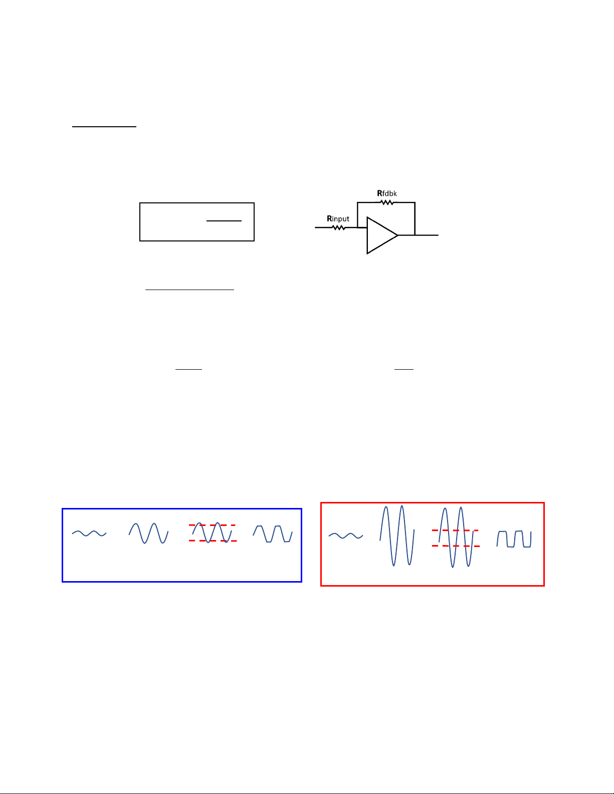
This is how this circuit works: (It’s simple… really!)
Short version: Two amplifiers amplify and clip-off the peaks of the waveforms, resulting in distortion.
“Clipping” is literally cutting-off the tops and bottoms of a signal.
In this circuit, the gain or “drive” of each stage is defined by the builder changing the GAIN 1 and GAIN 2 resistors.
The simple math for defining voltage gain in each stage of an Operational Amplifier (“Op-Amp”) is:
Where Rinput is the input or “GAIN” resistor, and Rfdbk is the “feedback” resistor.
In this circuit, the Rfdbk is fixed at 100k, but the builder chooses the values for the Rinput: The “GAIN” resistors.
•When a 10k resistor is chosen as the GAIN resistor, the voltage gain is 100k ÷ 10k - a 10x gain (amplification)
•If a 5k resistor is chosen, the gain is 100k ÷ 5k –a 20x gain (amplifies 20x).
In other words, for every millivolt that goes in, 10mv (or 20mv) comes out. Your choice.
However, we are here to distort the signal. We don’t want clean gain, we want dirty gain. That is where the
“clipping diodes” come in. The amplified signal goes into the clipping diodes which distorts it like this:
A diode allows voltage to pass in one direction but blocks it in the other direction. That blocking happens at
different voltages in each of the 3 types of diodes included in this kit. With 2 diodes facing the opposite direction in
the feedback circuit, the voltage peaks are literally “clipped-off,” resulting in distortion of the signal.
•When you amplify the signal just a little (low gain), just the very tips of the peaks are clipped-off.
•When you amplify the signal a lot (high gain), a lot of the peaks get clipped and it is more distorted.
•The more the peaks are “squared-off” the more “distorted”the signal sounds:
We are also limited by the 9-Volt power supply, or 4.5v on each side of the waveform. If the diodes do not clip-off
enough signal, then the Op-Amp will clip the signal as well.
This circuit generates distortion at 4 different points in this circuit: 2 sets of clipping diodes, plus 2 Op-Amps. The
distortion from Gain Stage 1 passes into Gain Stage 2, so if you clip the signal heavily in Gain stage 1, Gain stage 2
will clip it even more. Different Op-Amps can also sound different when they clip, based on their internal circuitry.
GAIN =
Rfdbk
Rinput
Input Signal
After low gain
Diode Clipping
Input Signal
After High gain
Diode Clipping
Slightly
distorted
(“clipped”)
signal
Heavily
distorted
(“clipped”)
signal
AUSTINDRIVE Assembly Tutorial Rev 3.02 December, 2020
5
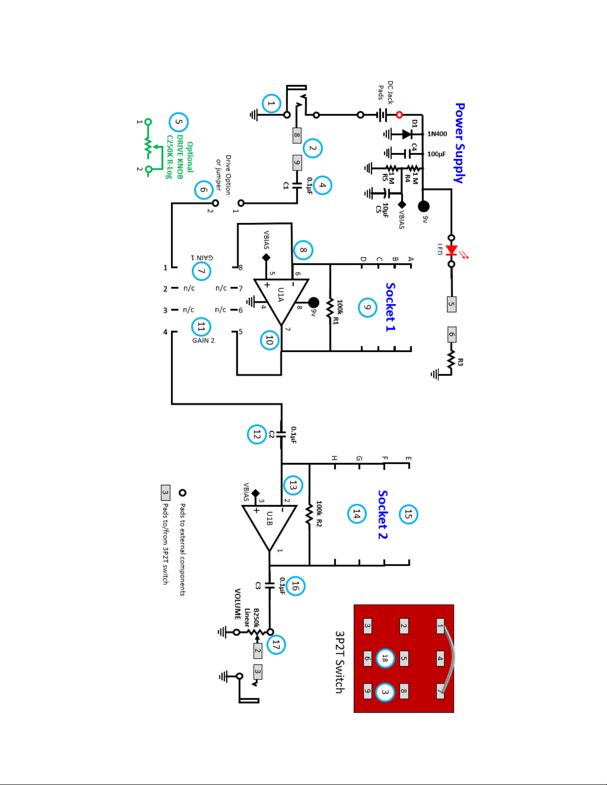
THEORY OF OPERATION (Numbered on the next page)
1. The 9V power circuit is completed (powered-on) when you insert a guitar cable into the input
2. The signal from the guitar goes through two poles of the 3-Pole, Double-Throw (3PDT) switch
3. The switch either jumpers the signal directly to the output (“True Bypass”), or to the drive circuit
4. Through the drive circuit, the signal passes through a DC-blocking capacitor, C1
5. If a drive knob is installed, signal is reduced by a C250k, reverse-logarithmic potentiometer
6. If a drive knob is not installed, a jumper is installed instead.
7. The signal passes through the GAIN 1 resistor, which defines the gain for Op-Amp #1 (previous page)
8. It enters Stage 1 of the op-Amp, U1 on Pin 6.
oThis is the “inverting input” of this Op-Amp, and it flips the phase 180°
9. The feedback loop contains the feedback resistor R1, and clipping diodes which clip the peaks of the signal
oIf there is high gain in the circuit, more clipping happens = more distortion in Gain Stage 1
oAlso, different diodes clip the signal differently. (“Hard” or “Soft” clipping here.)
10. The distorted signal comes out of the first Op-Amp on Pin 7
11. The signal goes to the GAIN 2 resistor, which defines the gain for Op-Amp #2 (previous page)
12. Before going into the next Op-Amp, the signal passes through another DC-blocking capacitor, C2
13. Like Gain Stage 1, the signal enters Gain Stage 2 of Op-Amp, U1 on Pin 2
oThis is also an “inverting input”- so the phase flips 180° again, restoring the correct phase
14. The Gain Stage 2 feedback loop contains a feedback Resistor R2, and clipping diodes
oMore gain here distorts the signal more, especially if it was heavily distorted by Gain Stage 1
oAlso, different diodes clip the signal differently. (“Hard” or “Soft” clipping here.)
15. The second gain stage socket also has room for a filter capacitor, which will reduce high-frequencies
oWith no capacitor here, all frequencies are allowed to pass through to the output
oAs this capacitor value gets larger, more high-frequencies are removed.
oA capacitor tends to “smooth” the sound of the distortion, making it less “harsh”
16. Out of the second op-amp on Pin 1, the signal passes through a final DC-blocking capacitor, C3
17. The signal then enters a B250k linear potentiometer
oWhen turned “up,” the signal passes through without any resistance, for the loudest volume.
oWhen turned “down,” more and more of the signal is shorted to ground, reducing the output
volume of the pedal.
oThis knob helps match the distorted volume to the clean (“True-Bypass”) volume.
oThe volume knob does not increase or decrease the distortion… only the output level.
18. The red LED is turned on/off with the pedal by passing voltage through the 3rd pole of the 3PDT switch
Notes to create a unique tone:
•Try a high-gain setup, then use a filter capacitor to reduce harsh high frequencies for a smoother tone
•Try different-value GAIN resistors, diodes, and capacitors with each of the 4 different Op-Amps
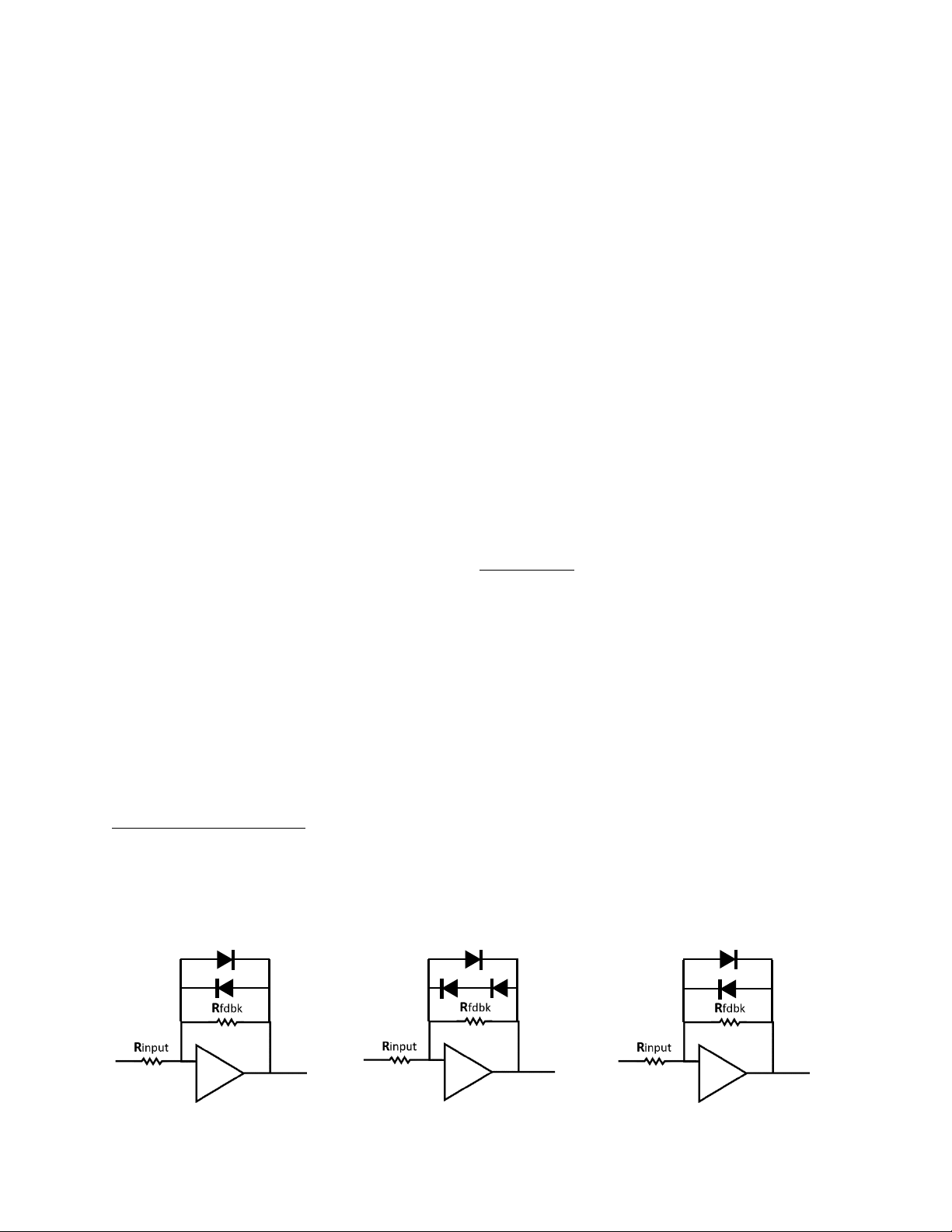
•You can mix/match diodes, or point 2 in one direction and one in the other, in parallel or in series.
•Two diodes in series clip the signal less than a single diode, also known as “uneven clipping”
•Some vintage pedals use these tricks. Here are some typical diode setups:
1N914
1N400x
Standard, “Even” clipping with
matching diodes
“Uneven” clipping with 2 pointing in one
direction, and one pointing the other
“Uneven” clipping with 2
different diodes
AUSTINDRIVE Assembly Tutorial Rev 3.02 December, 2020
6
Theory of Operation
4

AUSTINDRIVE Assembly Tutorial Rev 3.02 December, 2020
7
DRILL THE ENCLOSURE (Before any graphics are applied)
NOTE: Most kits come with pre-drilled enclosures, but a few “budget-friendly”kits do not.
I have drawn templates for marking the holes below. Print this page onto regular paper and cut
them out around the outside edges.
I also have .stl files for 3D printing punch templates. Customers can email me for the link.
NOTE: IF YOU ARE DRILLING YOUR OWN YOUR HOLES WITH THESE PAPER TEMPLATES:
LOCATIONS MAY NOT BE “ABSOLUTELY PERFECTLY”ALIGNED.
There are variations between printers and programs, so if you are
creating your own graphics: I strongly advise creating graphics that
are not aligned to the holes.
The top graphic (with 4 crosshairs) is intentionally smaller than the
actual face of the enclosure, and must be centered by eyeball. Once
centered, tape it down and center-punch the marks. I recommend
using a spring-loaded center-punch.
Carefully remove the top template. Align the short edge near the
switch crosshair (on the left below, in RED) with the end-face edge of
the enclosure to mark the DC Jack
Use the INPUT/OUTPUT template to mark the input/output JACK
locations, one on each side, at the correct end: Near the switch.
If my descriptions seem confusing, look at the photos to confirm.
+
+
Open Side
INPUT/OUTPUT JACKS
(1 per side)
Use the red crosshair to
mark the DC jack
location on this end face.
+
+
+
+
Mark this center hole ONLY if
you have a DRIVE knob!!
TOP TEMPLATE
AUSTINDRIVE Assembly Tutorial Rev 3.02 December, 2020
8
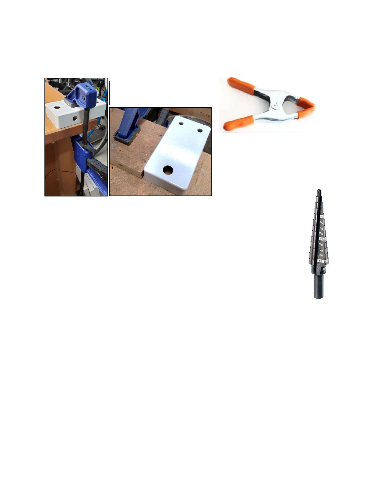
While drilling the enclosure, block or clamp the enclosure so it does not spin.
Keep the enclosure from spinning while drilling by pressing it against a piece of wood that is
clamped to the table with clamps or heavy spring clips.
Don’t drill into your table! - The space under the enclosure must clear the table!!
The hole sizes are:
•LED ¼inch (6.2mm)
•Volume/Drive Pot 9/32 inch (7mm)
•Input/Output Jacks ⅜Inch (9.5mm)
•Switch + DC Jack ½Inch (12.7mm)
If you buy a step-drill as shown here, make sure it has all these hole sizes, or
be prepared to use a round file to enlarge small holes.
Clamped or Blocked to prevent
movement while drilling.
Heavy-Duty spring
clamp with rubber tips
Milwaukee Step Drill
P/N 48-89-9201
⅛
to ½Inch (~$25)
AUSTINDRIVE Assembly Tutorial Rev 3.02 December, 2020
9
APPLY THE GRAPHICS (Drill first, Label second!)
For workshops and customers designing their own graphics, use the AUSTINDRIVE Graphics
Creator on Google Slides. Labels will be printed from your artwork.
All other kits have a graphics label included, or search YouTube to learn how to make your own
graphic labels without me!
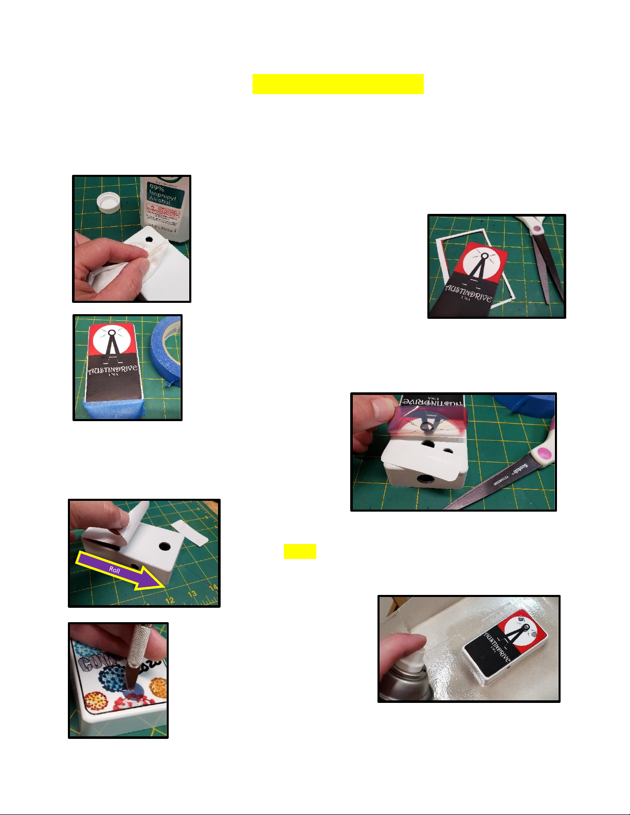
Clean the face of the pedal with Isopropyl Alcohol and let it dry.
However, do not wet the label or clean it with cleaners. The graphic
may rub-off.
Use sharp scissors to carefully trim the
edge of the included label around the
outside, leaving the black line as the edge.
Before you remove the label backing, center the label on the enclosure
and lightly tape it down across one side with painter’s tape.
Leaving the painter’s tape on one end, peel the
backing on the opposite end, cut off a small section
of the backing, and press that end of the label onto
the enclosure.
Remove the painter’s tape, then continue to peel the backing of
the label, “rolling”the label onto the enclosure.
Spray the newly labeled enclosure
with several coats of clear paint to
seal the edges, and set aside to dry
for at least 2 hours, preferably
overnight.
Cut out the holes with an X-Acto knife or razor blade, cutting with
downward motions to avoid peeling-up the label.
AUSTINDRIVE Assembly Tutorial Rev 3.02 December, 2020
10
PREPARE YOUR PARTS AND WORKSPACE
Clean off your bench or prepare a nice workspace where you won’t burn a kitchen tabletop or
tablecloth. Having a nice area ahead of time really does help.
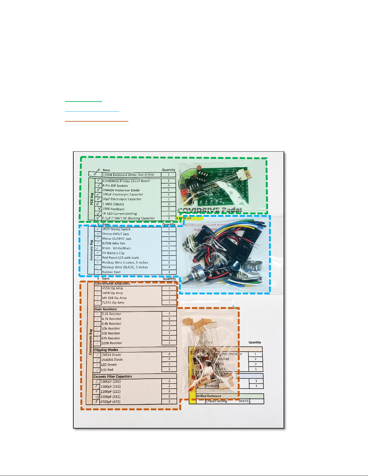
NOTE: There are 3 bags in this kit, plus the enclosure. (+ 1 bag if you ordered a Drive Knob)
•The PCB Bag has the green printed circuit board, sockets, and a few other parts in it.
•The Enclosure Bag has the jacks, switches, pots, and multi-colored wires in it.
•The Components Bag has ~40 resistors, capacitors, diodes, op-amps and LED’s in it.
Because there are MANY different resistors included. You will need a meter to measure the
resistors before soldering. I highly recommend a magnifying glass to verify your soldering, too.
AUSTINDRIVE Assembly Tutorial Rev 3.02 December, 2020
11
STUFF THE CIRCUIT BOARD
Find the PCB Bag. It has the following components:
4) 8-pin Sockets
3) “104” (0.1µF) Caps
2) 1MEG resistors
2) 100k resistors
1) 1k resistor
1) 100µF Electrolytic cap
1) 10µF Electrolytic cap
1) 1N400xDiode (x= 1, 4 or 7)
1) Printed Circuit Board
Check-off each step in the check box at left
IMPORTANT:
Do not stuff all the components into the board, then try to solder them all at once.
Trust me on this: Too many legs make it extremely easy to miss soldering one!
Maybe do 2 or 3 at a time, solder, cut-off, and repeat. But not everything all-at-once.
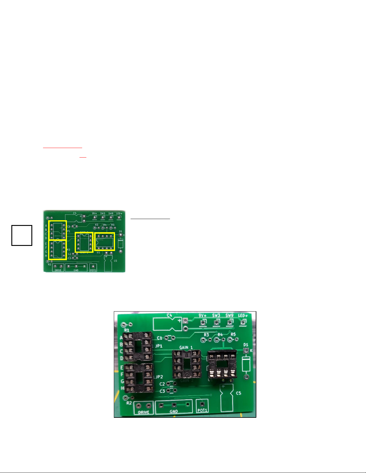
8-Pin Sockets
Install a socket into each location, one at a time.
NOTE: Legs can get bent during shipping. Just bend them back.
Each socket has a small “u-shaped” notch on one edge. Match
that cutout with the notch printed on the board. On the back-side
of the board, bend- the legs outward so that the sockets don’t
fall-out when you turn-over the board.
Solder all 32 legs now. It’s great practice for everything else!
Check-Off
4 Sockets

AUSTINDRIVE Assembly Tutorial Rev 3.02 December, 2020
12
D1 (1N400x) Diode
Bend the 1N400x diode with your fingers so it fits in the holes.
A diode is “polarized” and current only flows one way.
Put the diode through the holes so that the stripe on the diode
matches the stripe on the board. Spread the leads slightly so that the
diode stays in the board. Solder the leads from the back side, and cut-
off the legs. This diode protects the circuit from reversed 9V leads or a
bad Power Supply.
Save the two cut leads from this diode. Or from another component.
You will need them later.
NOTE: Resistors are NOT “polarized.” They can be installed and bent either way.
The bodies of the resistors may be tan, brown, or blue, depending on the manufacturer.
R1 & R2 (100k) Resistors
Bend one lead of each resistor back-over on
itself, so that both legs point the same direction.
Install the resistors upright.
These are fixed feedback resistors in the
gain stages.
R3 (1k Ohm) Resistor
Bend one lead of the resistor back-over on itself, so that both legs
point the same direction. Install the resistor upright.
This 1K resistor keeps the LED from burning-out.
1k:
Brown Black Red
Check-Off
R3
100k:
Brown Black Yellow
Check-Off
R1 & R2
Check-Off
D1

AUSTINDRIVE Assembly Tutorial Rev 3.02 December, 2020
13
R4 & R5 (1 MEG) Resistors
Bend one lead of each resistor back-over on itself, so that both
legs point the same direction. Install resistors upright.
These resistors divide the 9V equally into
+/- 4.5v, to “center-bias” the Op-Amps.
C1, C2 and C3 (0.1µF, “104”) Ceramic Capacitors
Line-up the three 0.1µF (104) capacitors in the column near the
center of the board. These capacitors block DC voltage from the
audio stages. DC offset would alter the waveform in the next gain
stage.
These capacitors are not polarized. They can be installed either way,
but I like to have the “104” number facing the same way on all of
them.
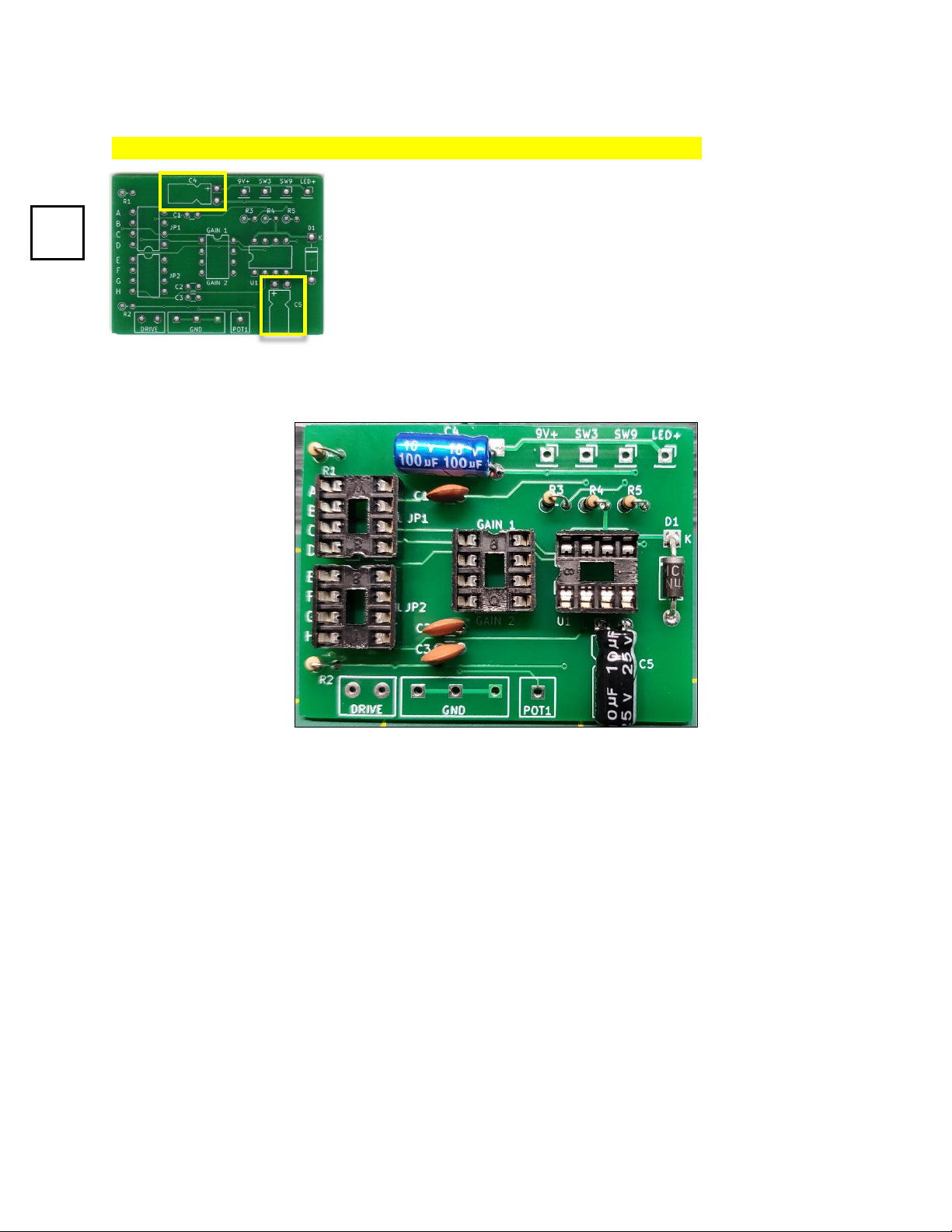
C4 & C5 (100µF and 10µF) Electrolytic capacitors
Holding each capacitor in your right hand, with the stripe towards you, bend the legs of the
100µF and 10µF capacitors 90° UP.
NOTE: The colors of the capacitors in your kit may vary from these images.
1 MEG:
Brown Black Green
Check-Off
R4 & R5
Check-Off
C1, C2 & C3
AUSTINDRIVE Assembly Tutorial Rev 3.02 December, 2020
14
Both electrolytic capacitors lay flat on the board. They must be installed correctly.
These capacitors ARE polarized. The longer leg goes into the square “+” pad.
C4 is the 100µF capacitor at the top, that lines-up horizontal.
C5 is the 10µF capacitor at the bottom, that lines-up vertical.
These capacitors filter-out leftover AC voltage from a power
supply, and store energy for use during short, quick transient
bursts when the pedal is being asked to deliver 100% of its design
capability.
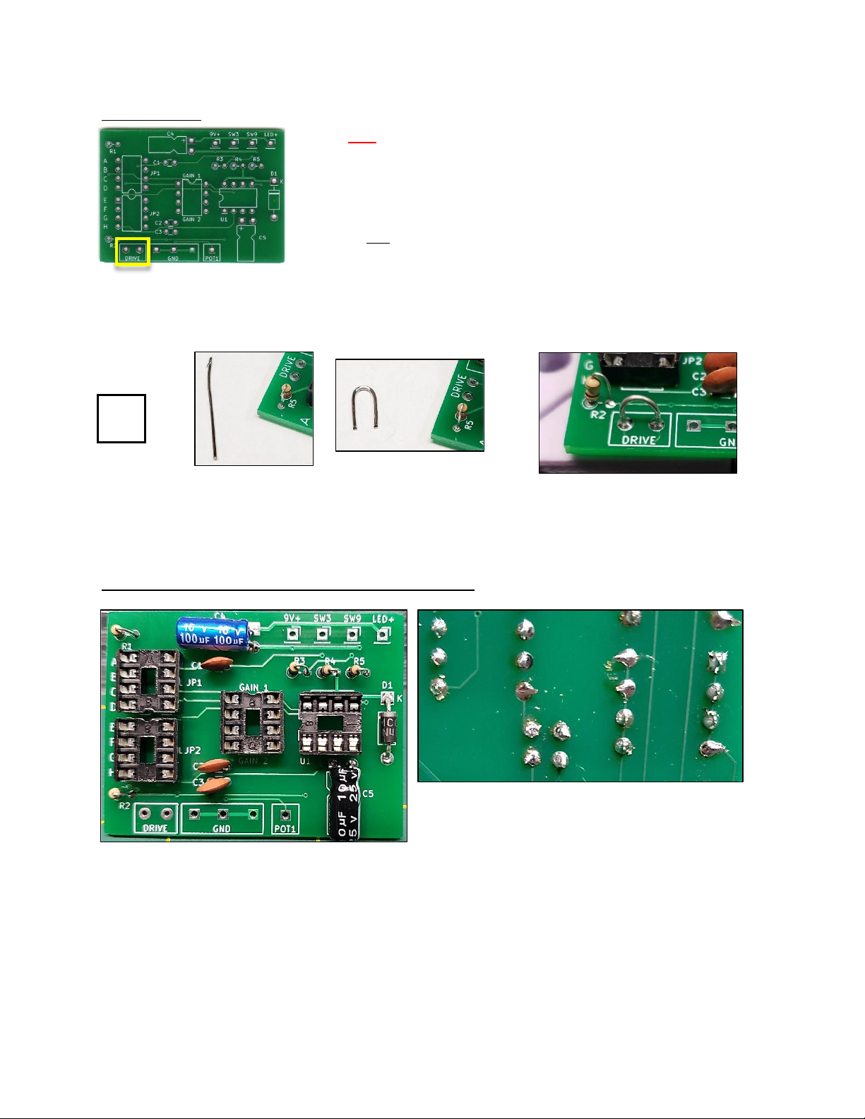
Your board should look a lot like this now:
Please double-check your components with this image.
Again, your 10 µF and 100µF capacitor colors may differ from those in this image, and the
bodies of the resistors may be tan, brown, or blue, depending on the manufacturer.
Check-Off
C4 & C5
AUSTINDRIVE Assembly Tutorial Rev 3.02 December, 2020
15
DRIVE Jumper
IF YOU ARE INSTALLING THE OPTIONAL DRIVE KNOB:
Leave these pads empty for now.
We will wire them in the final step: Wiring the Enclosure.
If you are not installing a DRIVE knob, you must place a jumper
between these two pads:
Use one of the legs you previously cut-off from a resistor, diode or capacitor, and bend it into a
U shape. Install that jumper into the DRIVE pads and solder it. Cut the legs off the back like the
other components, leaving a small “horseshoe” or “rainbow” loop here.
RECOMMENDATION: Leave the jumper a little higher than the board, not pressed down flat.
Later, if you want to upgrade and install a drive knob, the jumper will be easier to cut, and it will
provide two short “pins” to wrap the DRIVE pot wires to before soldering.
Double-check your soldering with a magnifying glass.
Review your check boxes from the pages above.
Use magnification to look for pads that you missed soldering, and solder bridges where solder
has connected 2 pads, especially at the resistors. Some pads are very close together.
The two rows of pads on the top and bottom edges of the board are where the wires from the
jacks and switches are soldered in the final step: Wire the Enclosure.
If you don’t have a
drive knob
Check-Off
DRIVE Jumper

AUSTINDRIVE Assembly Tutorial Rev 3.02 December, 2020
16
PREPARE YOUR PARTS AND WORKSPACE
Clean off your bench or prepare a nice workspace where you won’t scratch a kitchen tabletop
or tablecloth. Having a nice area ahead of time really does help.
Inside your enclosure, use a sharpie to write the names of the holes from the inside.
MARKING THE INSIDE REALLY HELPS. Trust me.
You will spend several hours building the pedal “upside-down.”This can be confusing when you
go to use it “right-side up.”I spent many minutes wondering why my prototype pedals didn’t
work…because I had the guitar plugged-into the OUTPUT, or I thought my Drive knob was all
the way down, when it was my Volume knob that was all the way down!
Twisting Wires
Some wires go to almost the same point on the board, so twisting a pair of wires helps
assembly. Use a slow drill, pinch the wires with your fingers, and slowly twist wire pairs if you
need to. Not more than 2 turns per inch, or about 1 turn per cm.
NOTE: AUSTINDRIVE Kits have pre-twisted wire pairs for certain connections.
AUSTINDRIVE Assembly Tutorial Rev 3.02 December, 2020
17
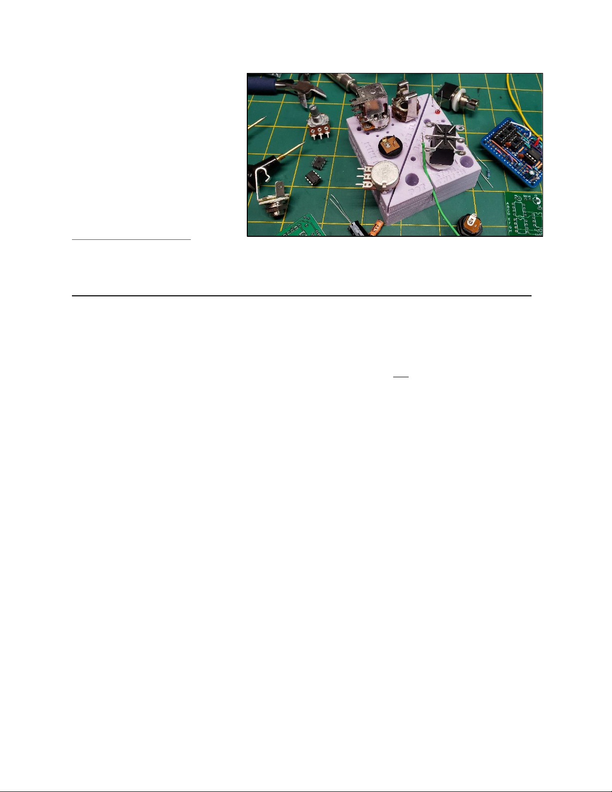
THE PEDAL PORT
Throughout this tutorial, I use
The Pedal Port, a silicone parts
holer molded exclusively for
pedal-building. It grips parts tight
without scratching, and it doesn’t
suck-out the heat of soldering.
The Pedal Port is available from
www.ThePedalPort.com
Why aren’t these parts soldered onto the Circuit Board?
One answer: Reliability.
Circuit boards, metal enclosures, solder lugs, input jacks and guitar cable plugs don’t bend.
When you constantly plug & unplug rigid components into a circuit board, tweak knobs, and stomp on
switches, those soldered connections on a printed circuit board (“PCB”) will fail. It may take years, but
when rigid components move, solder joints on PCBs crack - and electronic things stop working. This is a
major reason why modern electronics and appliances only last a few years, but a 1960’s Tube Amp is still
running.
When rigid connections are “insulated” from the circuit board by a flexible wire, those connections to
the PCB last longer. Maybe forever.
Yes. There are guitar pedal circuit boards where everything is neatly soldered to a circuit board, and it all
fits nicely into an enclosure. That takes all the fun out of it for me. I like wires and colors.
AUSTINDRIVE Assembly Tutorial Rev 3.02 December, 2020
18
PRE-WIRE THE JACKS POTS AND SWITCHES
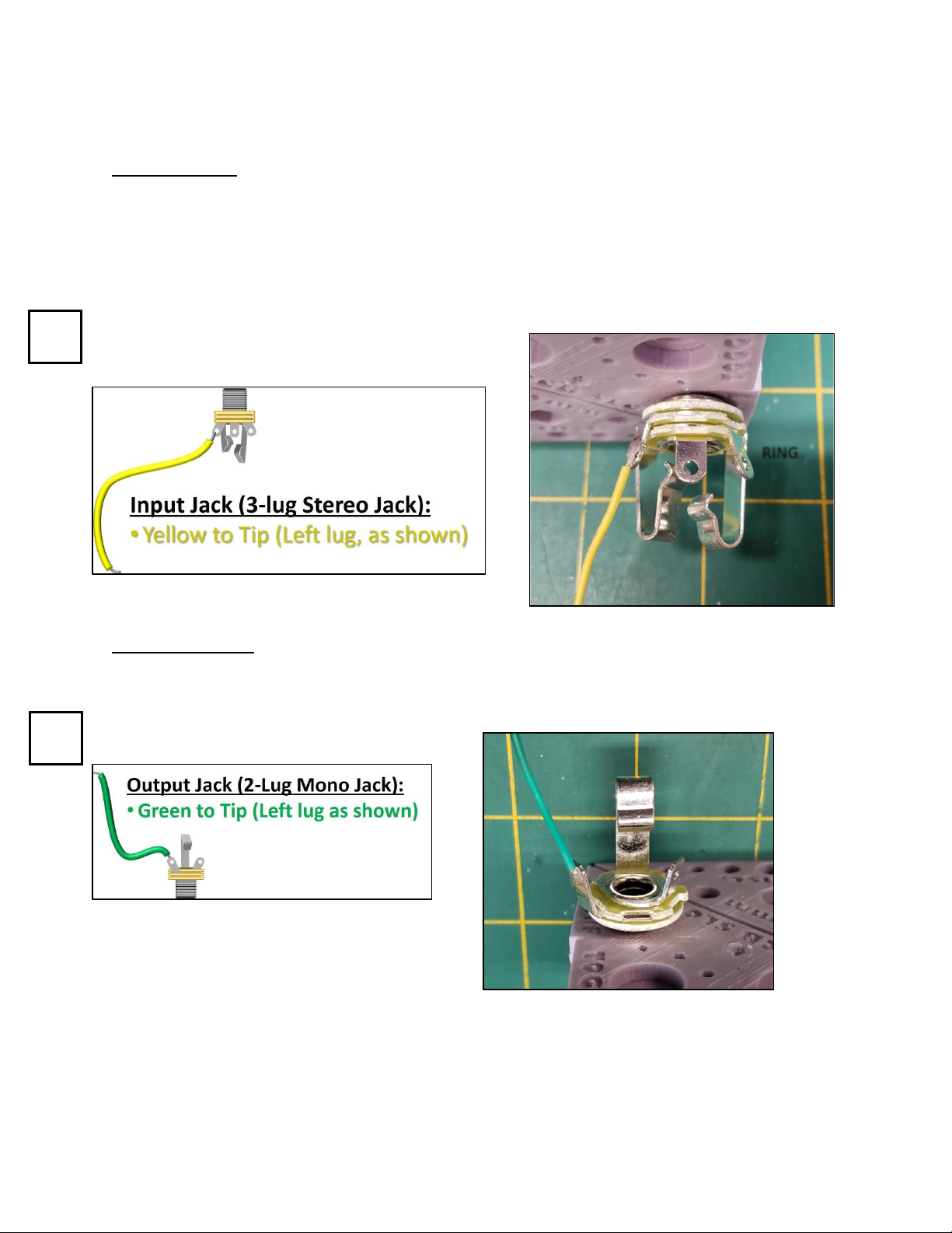
THE INPUT JACK has 3 connections, commonly called a “Tip/Ring/Sleeve”(TRS) or “Stereo” jack.
When a guitar cable is plugged-in, the ring makes contact with ground, connecting the DC
Power Jack for as long as a cable is plugged-in. Unplug to de-energize the circuit or save battery
if you’re using the 9V battery adapter cable.
The diagram here shows the installed position in the enclosure: Solder lugs UP.
•Yellow to Tip (Left lug)
•
THE OUTPUT JACK has 2 connections, commonly called a “Tip/Sleeve” (TS) or “Mono” jack.
The diagram here shows the installed position in the enclosure: Solder lugs UP.
•Green to Tip (Left lug)
TIP
SLEEVE
RING
Check-Off
Check-Off
TIP
SLEEVE

AUSTINDRIVE Assembly Tutorial Rev 3.02 December, 2020
19
THE VOLUME POT is a B250k Pot with 3 connections. The outside two are the ends of a “C-
shaped” resistor, and the center connection is a moveable point (“wiper”) along that resistor.
Turning the knob changes the resistance between the center terminal and each end. The
Volume Pot literally shorts more of the signal to ground, as you turn it down.
With wires pointing LEFT:
•RED to Center
It really helps to write a “V” on this potentiometer
if you have more than one knob on your pedal.
Use a leftover leg from one of the PCB components to make a jumper between Pins 1 and 7.
THE FOOT SWITCH has 9 connections. It is a single button that controls 3 switches at one time.
•Switch 1 is on pins 1, 2, and 3 (This will be the input Switch)
•Switch 2 is on pins 4, 5, and 6 (This will be the LED on/off Switch)
•Switch 3 is on pins 7, 8, and 9 (This will be the output Switch)
It is a “3-Pole”(3 switches in one), “Double-Throw”(2-position) switch, AKA: a “3PDT Switch.”
If you want more information about this type of switch (I know you do!), Google: “3PDT Switch”
Jumper between pins 1 and 7
Cut-off the ends of the jumper
Check-Off
Check-Off
AUSTINDRIVE Assembly Tutorial Rev 3.02 December, 2020
20
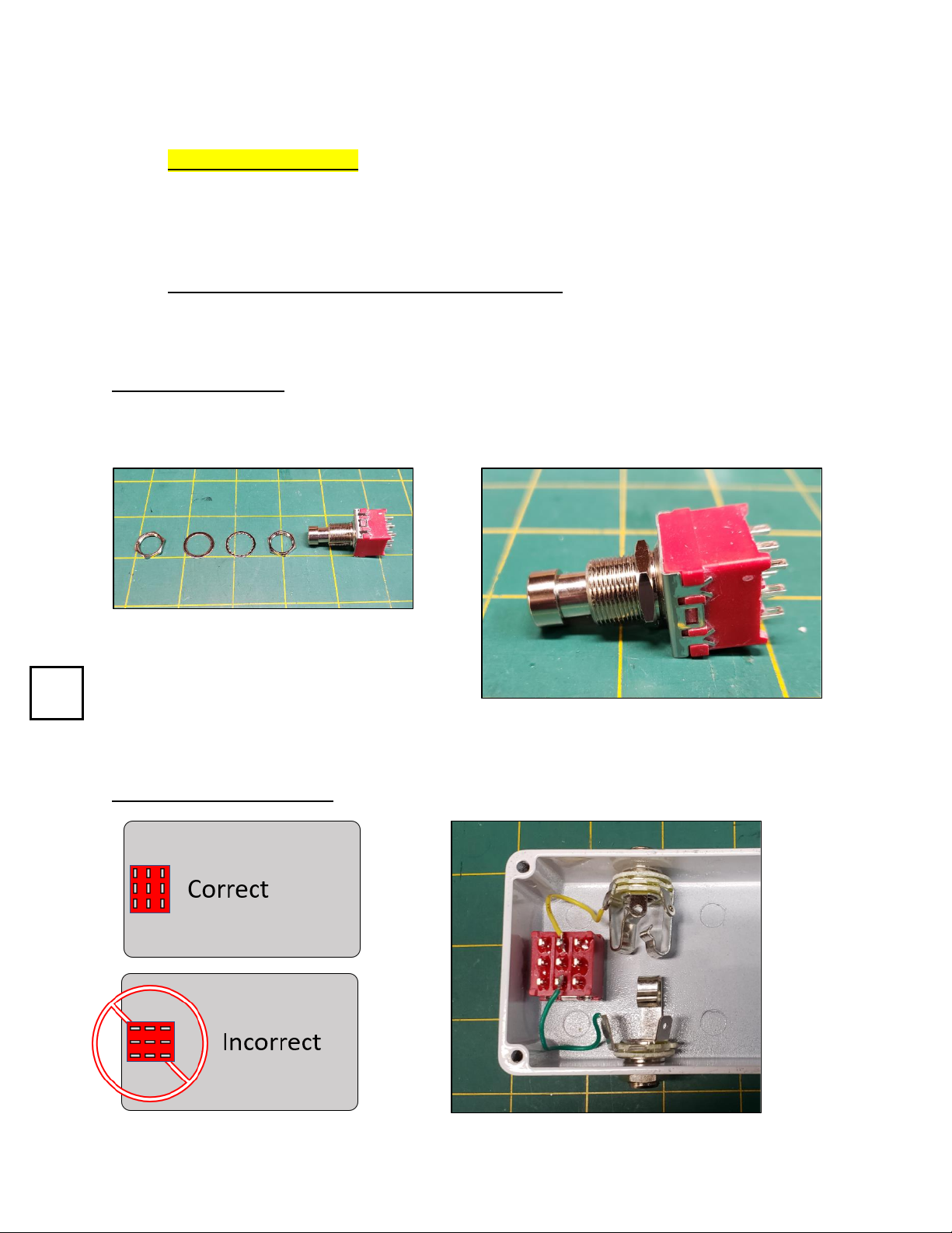
Otherwise, the things you need to know to continue are:
1. The orientation matters. The pins are rectangles: Longer in one direction than the
other. In the diagrams above and below, the pins are taller than they are wide. If the
switch is oriented like this diagram in your enclosure, the pin numbers will be correct.
2. The switch can be turned 180° and still be wired correctly.
3. View the images above and see photos of the complete build if you are unsure.
4. Don’t forget to put a jumper between pins 1 and 7. Use a cut-off leg from one of your
resistors or capacitors from the PCB soldering section.
Install the Foot Switch
The foot switch has 2 lock nuts, a tooth washer and a flat metal washer. Remove everything
then thread one nut on the switch so that goes all the way to the bottom of the shaft:
Install the tooth washer on top of that first
nut, and put the switch through the enclosure
from the inside. With the lock nut and the
tooth washer inside the enclosure, the flat
metal washer and the remaining nut are installed from the outside. Be sure the rectangle lugs
are oriented vertically as shown. Your switch may vary in color from these images.
Installation in the enclosure:
Check-Off
Table of contents


