AUTEC Dynamic Series User manual

Original instructions
DYNAMIC SERIES
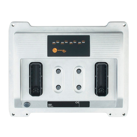
Receiving unit PCR
INDEX
1 Description ............................................................................................................ 2
2 Technical data ....................................................................................................... 3
3 Technical data sheet ............................................................................................. 3
4 Plates ..................................................................................................................... 4
5 Light signals .......................................................................................................... 4
5.1 POWER LED (green) ....................................................................................... 4
5.2 ALARM LED (red) ............................................................................................ 5
5.3 STATUS LED (blue) ......................................................................................... 5
5.4 LED RUN (green) e LED ERR (red) ................................................................. 5
5.5 SETUP LED (yellow) ........................................................................................ 5
6 Malfunction signalled by the receiving unit ........................................................ 6
AUTEC
LIPCRE00-00

2
LIPCRE00-00
Description
AUTEC - Dynamic Series
1 Description
Aplugs
Bmounting holes
CAntenna
DLED
ETechnical data plate
FRadio remote control identication
plate
The receiving unit is interfaced with the machine through the outputs and their wiring and/or
through a CAN network (of which it is a master node).
The STOP (STP_1 and STP_2) and SAFETY (SAF_1 and SAF_2) outputs are some of the
receiving unit's outputs.

AUTEC - Dynamic Series
Technical data 3
LIPCRE00-00
2 Technical data
Power supply ........................................................................................................ 8-30V
Antenna .............................................................................................................. dedicated
Rated current of STP_1 and STP_2 outputs .................................................... 2A (30V )
Rated current of the SAF_1 output .................................................................. 2A (30V )
Rated current of the SAF_2 output .................................................................. 2A (30V )
Rated current of digital outputs ........................................................................ 2A (30V )
Rated current of analogue outputs (PWM) ....................................................... 2A (30V )
Rated current of analogue outputs (voltage) ............................................... 10mA (28V )
Protection of power supply (resettable fuse) ............................................................... 1.3A
Protection of outputs (fuse F1) ....................................................... 10A (32V , autofuse)
Protection of the SAF_1 output (fuse F2) .......................................... 3A (32V , autofuse)
Protection of the STP_2 output (fuse F3) .......................................... 3A (32V , autofuse)
Protection of the SAF_2 output (fuse F5) .......................................... 3A (32V , autofuse)
Protection of the STP_1 output (fuse F4) .......................................... 3A (32V , autofuse)
Housing material ................................................................................................ aluminum
Protection degree ....................................................................................... IP65 (NEMA 4)
Dimensions .................................................................... 260x160x70mm (10.2x6.3x2.7In)
Weight ............................................................................................................. 2kg (4.4Lb)
3 Technical data sheet
The technical data sheet contains the wiring diagram showing the connection between the
receiving unit and the machine. It also contains the transmitting unit conguration and shows
the matching between commands sent and machine functions/movements.
Each technical data sheet must be lled in, checked and signed by the installer, who is
responsible for a correct wiring.
A technical data sheet must always be kept toghether with this manual (always keep a copy
of the technical data sheet when it is used for administrative purposes).
The wiring of the receiving unit outputs must always reect the wiring
indicated in the technical data sheet.

4
LIPCRE00-00
Plates
AUTEC - Dynamic Series
4 Plates
The receiving unit has the following plates:
Plate Position Content
radio remote control
identication plate On the casing of the receiving unit
Radio remote control
serial number (S/N), bar
code and manufacturing
year.
technical data plate On the casing of the receiving unit
MODEL, TYPE and main
receiving unit technical
data, marking and
possible radio remote
control marks.
5 Light signals
The receiving unit PCR has six LEDs:
-POWER is green
-ALARM is red
-STATUS is blue
-RUN is green
-ERR is red
-SETUP is yellow
5.1 POWER LED (green)
The POWER LED indicates the status of the receiving unit and of the radio link.
The POWER LED... Meaning
…is o The receiving unit is not powered.
...is on The receiving unit is powered and radio link is missing.
… blinks The receiving unit is powered and radio link has been
established.

AUTEC - Dynamic Series
Plates 5
LIPCRE00-00
5.2 ALARM LED (red)
The ALARM LED warns about anomalies in the receiving unit.
The ALARM LED... Meaning
…is o The receiving unit works correctly.
... blinks once Error on the STOP outputs.
... blinks twice Error on the SAFETY outputs.
... blinks three times Error on the outputs corresponding to direction
commands.
... is on The receiving unit does not work correctly.
5.3 STATUS LED (blue)
The STATUS LED warns about anomalies on the outputs or on the power supply and indicates
the reception of data from the transmitting unit.
The STATUS LED... Meaning
…is o No radio link.
... blinks slowly Over-voltage on power supply.
... blinks fast The receiving unit receives data from the transmitting unit.
... is on Over-current in one of the PWM analogue outputs.
5.4 LED RUN (green) e LED ERR (red)
RUN and ERR LED signals are congurable during the maschine installation: it is recommended
to respect the guidelines of the CANopen® standard, CiA recommendation 303-3.
5.5 SETUP LED (yellow)
SETUP LED signals are congurable during the machine installation.

6
LIPCRE00-00
Malfunction signalled by the receiving unit
AUTEC - Dynamic Series
6 Malfunction signalled by the receiving unit
Use the light signals on the receiving unit to identify the radio remote control malfunction.
If the problem persists after the suggested solution has been carried out, contact the support
service of the machine manufacturer.
Signals Possible reason Solutions
The POWER LED is o. The receiving unit is not
powered.
Disconnect the power supply
and restore it after 5 minutes
to make sure that a restorable
thermal fuse integrated in the
receiving unit has not been
activated.
Correctly plug in the
connecting plug and power on
the receiving unit.
The POWER LED is on. No radio link. Bring the transmitting unit
closer to the receiving unit.
The ALARM LED blinks
once. Error on the STOP outputs.
Make sure that fuses F3 and
F4 are intact.
Correctly plug in the
connecting plug.
Make sure that the STOP
outputs are wired correctly.
The ALARM LED blinks
twice. Error on the SAFETY outputs.
Make sure that fuses F2 and
F5 are intact.
Correctly plug in the
connecting plug.
Make sure that the SAFETY
outputs are wired correctly.
The ALARM LED blinks three
times.
Error on the outputs
corresponding to direction
commands.
Contact the support service of
the machine manufacturer.
Make sure that the outputs of
direction commands are wired
correctly.
The ALARM LED is on. The receiving unit does not
work correctly.
Contact the support service of
the machine manufacturer.

AUTEC - Dynamic Series
Malfunction signalled by the receiving unit 7
LIPCRE00-00
Signals Possible reason Solutions
The STATUS LED blinks
slowly. Over-voltage on power supply.
Make sure that the receiving
unit power supply is within the
voltage limits provided in the
technical data.
The STATUS LED blinks fast
and irregularly.
The receiving unit loses some
data sent by the transmitting
unit.
Bring the transmitting unit
closer to the receiving unit.
If this signal persists, contact
the support service of the
machine manufacturer.
The STATUS LED is on. Over-current in one of the
PWM analogue outputs.
Contact the support service of
the machine manufacturer.

Other manuals for Dynamic Series
6
Table of contents
Other AUTEC Controllers manuals
