AUTO GYRO RotorSport CALIDUS User manual

Copyright of RotorSport UK Ltd
Document number RSUK0060
Page 1 of 101 Page issue 4, dated 01.07.13
Pilots Handbook
Gyroplane Type CALIDUS (UK spec only)
RotorSport UK Ltd
Poplar Farm
Prolley Moor
Wentnor
Bishops Castle
SY9 5EJ
Company Reg No 5486550
Phone: +44 (0) 1588 650769
Fax: +44 (0) 1588 650769
Email: [email protected]
Approval number DAI/9917/06

Copyright of RotorSport UK Ltd
Document number RSUK0060
Page 2 of 101 Page issue 6, dated 12.04.16
Applicability
Aircraft Registration: G-
Aircraft serial no. RSUK/CALS/
Engine type: Rotax 912ULS or 914UL
Engine serial No:
Rotor blade type & diameter: Autogyro 8.4m rotor system,
(orange end-caps only)
or
Autogyro 8.4m RotorSystemII
(red caps only) when modified
under SB-039
or
Autogyro 8.4m Rotor System II
TOPP (blue end caps only)
NB: all types have silver spacers
(clamp profiles)
Propeller type: HTC 1,73m ground adjustable
propeller
or
IVO-prop DL3-68 in-flight variable
pitch propeller
NOTE!
This autogyro may be operated only under adherence to the
operation limits and the information contained in this
manual. The manual should be carried on board the aircraft.
The manual is not a replacement for theoretical and
practical training as to how to operate this machine. Failure
to adhere to its provisions or to take proper instruction can
have fatal consequences

Copyright of RotorSport UK Ltd
Document number RSUK0060
Page 3 of 101 Page issue 6, dated 12.04.16
Table of contents Page
1. GENERAL
1.1 Introduction 7
1.2 UK Authority for flight 7
1.3 Explanations and sensible safety measures 7
1.4 Aircraft description 9
1.5 Pictorial views 10
2. OPERATIONAL LIMITS
2.1 Introduction 14
2.2 Airspeed 15
2.3 Airspeed indicator marking 15
2.4 Rotor 15
2.5 Engine 16
2.6 Engine instruments 16
2.7 Weight and balance 16
2.8 Fuel 18
2.9 General placards 18
3. EMERGENCY PROCEDURE
3.1 Introduction 24
3.2 Engine failure 24
3.3 Engine start in the flight 25
3.4 Abandoning the aircraft 25
3.5 Smoke and fire 25
3.6 Gliding flight & forced landings 26
3.7 Precautionary landings 26
3.8 Loss of control 27
3.9 Engine shutdown 27
3.10 PIO/reduced rotor rpm 27
3.11 Vibration 28
3.12 Other equipment failure 29
3.13 Canopy open in flight 30
3.14 Loss of vision 30
3.15 Further Information (914 UL) 30
4. NORMAL OPERATIONAL PROCEDURES
4.1 Introduction 31
4.2 Rotor rigging 31
4.3 Daily inspection 39
4.4 Flight Operation 41
4.5 Normal procedures and check list 41
5. PERFORMANCE
5.1 Performance data 47
5.2 Further data 48
5.3 Height distance diagram 49

Copyright of RotorSport UK Ltd
Document number RSUK0060
Page 4 of 101 Page issue 6, dated 12.04.16
6. DESCRIPTION
6.1 Structure 50
6.2 Controls 50
6.3 Instrument panel 56
6.4 Wheels and Tyres 64
6.5 Seats and belts 64
6.6 Engine 65
6.7 Fuel system 70
6.8 Electrical system 73
6.9 Pitot and static pressure 76
6.10 Avionics 76
6.11 Navigation lights 77
6.12 Options and Modifications 77
7. HANDLING, SERVICE AND MAINTENANCE
7.1 Introduction 87
7.2 Regular maintenance requirements 87
7.3 Repairs 88
7.4 Ground handling & road transport 88
7.5 Cleaning and care 90
7.6 Winter operation 90
8. EQUIPMENT
8.1 Minimum equipment 92
8.2 Additional equipment 92
9. IVO-PROP IN-FLIGHT VARIABLE PITCH PROPELLER (OPTION) 93
9.1 Introduction 93
9.2 Function 93
9.3 Control 93
9.4 Manifold Absolute Pressure Indications 94
9.5 Circuit Protection 94
9.6 Pilot Training & Experience 94
9.7 Normal Procedures 95
9.8 Pre-Flight Inspection 96
9.9 Coping With Malfunctions 97
APPENDIX
I Change of ownership form 99
II Incident reporting form 100

Copyright of RotorSport UK Ltd
Document number RSUK0060
Page 5 of 101 Page issue 6, dated 12.04.16
Amendments Control Page
1. Where & when necessary RotorSport UK Ltd (hereafter referred to as RSUK) will issue
updates to this manual, and will notify known owners to review the changes via the RSUK
website with changes appropriately identified by a strike in the margin.
2. Aircraft operators are responsible for ensuring that amendments to their publication are
carried out immediately and in accordance with instructions contained in amendment
transmittal letters (where issued).
ISSUE
NUMBER
DATE
INSERTED
BY
ISSUE
NUMBER
DATE
INSERTED
BY
Initial
_______
________
11
1 14.01.11 12
2 12.09.11 13
3 02.04.12 14
4 01.07.13 Superceded –
Not Published 15
5.1 10.06.14 16
612.04.16 17
7 18
8 19
9 20
10 21
Issue Change summary
4 Warning on Binx nuts (p38), different rpm gauges (p62), nitrogen-
filled tyres (p64) and pressures clarified in Checklist. 5hr greasing
added (p39-40), ATR833 audio socket (p76), AI option (p62).
Improved pre-rotator gearbox (p44), cooler unblanking highlighted
(p91), turbo cooling note (p46), UL91 and Mogas E10 (p18), rotor
brake technique (p46), Section 3.15 introduced (p30), Clutch Brake
MC260 (p44)
5.1 Section 9 IVO-prop added (p93-98), info on MC-258 cabin heater on
P74 and 84 added.
6 TOPP rotor option added p2,p5,p6,p9,p14,p15,p19,p31,p32,p36,
p46,p48
Copyright of RotorSport UK Ltd
Document number RSUK0060
Page 6 of 101 Page issue 6, dated 12.04.16
LIST OF EFFECTIVE PAGES
Page
Issue
Date
Page
Issue
Date
Page 1 4 01.07.13 Page 51 2 12.9.11
Page 2 612.04.16 Page 52 2 12.9.11
Page 3 6 12.04.16 Page 53 2 12.9.11
Page 4 6 12.04.16 Page 54 2 12.9.11
Page 5 6 12.04.16 Page 55 2 12.9.11
Page 6 6 12.04.16 Page 56 5.1 10.06.14
Page 7 1 14.01.11 Page 57 3 02.04.12
Page 8 1 14.01.11 Page 58 2 12.9.11
Page 9 6 12.04.16 Page 59 2 12.9.11
Page 10 1 14.01.14 Page 60 3 02.04.12
Page 11 1 14.01.11 Page 61 3 02.04.12
Page 12 1 14.01.11 Page 62 4 01.07.13
Page 13 2 12.9.11 Page 63 2 12.9.11
Page 14 6 12.04.16 Page 64 4 01.07.13
Page 15 6 12.04.16 Page 65 2 12.9.11
Page 16 5.1 10.06.14 Page 66 2 12.9.11
Page 17 2 12.9.11 Page 67 2 12.9.11
Page 18 4 01.07.13 Page 68 2 12.9.11
Page 19 6 12.04.16 Page 69 2 12.9.11
Page 20 6 12.04.16 Page 70 2 12.9.11
Page 21 3 02.04.12 Page 71 2 12.9.11
Page 22 2 12.9.11 Page 72 2 12.9.11
Page 23 5 10.06.14 Page 73 2 12.9.11
Page 24 2 12.9.11 Page 74 5.1 10.06.14
Page 25 2 12.9.11 Page 75 5.1 10.06.14
Page 26 2 12.9.11 Page 76 4 01.07.13
Page 27 2 12.9.11 Page 77 4 01.07.13
Page 28 2 12.9.11 Page 78 2 12.9.11
Page 29 2 12.9.11 Page 79 2 12.9.11
Page 30 6 12.04.16 Page 80 2 12.9.11
Page 31 6 12.04.16 Page 81 2 12.9.11
Page 32 6 12.04.16 Page 82 2 12.9.11
Page 33 6 12.04.16 Page 83 2 12.9.11
Page 34 6 12.04.16 Page 84 5.1 10.06.14
Page 35 6 12.04.16 Page 85 2 12.9.11
Page 36 6 12.04.16 Page 86 2 12.9.11
Page 37 6 12.04.16 Page 87 3 02.04.12
Page 38 6 12.04.16 Page 88 3 02.04.12
Page 39 6 12.04.16 Page 89 3 02.04.12
Page 40 6 12.04.16 Page 90 2 12.9.11
Page 41 2 12.9.11 Page 91 4 01.07.13
Page 42 5.1 10.06.14 Page 92 2 12.9.11
Page 43 2 12.09.11 Page 93 5.1 10.06.14
Page 44 4 01.07.13 Page 94 5.1 10.06.14
Page 45 6 12.04.16 Page 95 5.1 10.06.14
Page 46 6 12.04.16 Page 96 5.1 10.06.14
Page 47 6 12.04.16 Page 97 5.1 10.06.14
Page 48 6 12.04.16 Page 98 5.1 10.06.14
Page 49 2 12.9.11 Page 99 5.1 10.06.14
Page 50 2 12.9.11 Page 100 5.1 10.06.14
RotorSport UK Ltd approval signatures for this Pilot Handbook
Signature:
Position: Test Pilot
Signature:
Position: Engineering Manager
Signature:
Position: Head of
Airworthiness

Copyright of RotorSport UK Ltd
Document number RSUK0060
Page 7 of 101 Page issue 1, dated 14.01.11
GENERAL INFORMATION
1.1 INTRODUCTION
This manual is provided to give pilots and instructors information which contributes to the
safe and efficient operation of this autogyro.
It also contains basic information from the aircraft manufacturer, as well as the legal basis
for flight.
Pilots of this aircraft must hold an appropriate type licence, with type conversion training
by an authorised instructor.
Pilots must make themselves familiar before flight with the special characteristics of this
autogyro. Pilots are obliged to read both this pilots manual and the maintenance manual
to ensure you are familiar with all equipment and aircraft structure/engine.
1.2 AUTHORITY FOR FLIGHT WITHIN THE UK
The legal basis for the operation of this CALIDUS autogyro is regulated in the
Airworthiness Approval Notification (AAN29266), issued by the Civil Aviation Authority
(CAA). It has been shown to comply with the requirements of BCAR Section T issue 3,
and is considered as a factory built aircraft.
It is supplied by RotorSport UK Ltd.
The aircraft is equipped and permitted for daytime VFR flight only.
1.3 EXPLANATIONS AND SENSIBLE SAFETY MEASURES
The manual is not a replacement for theoretical and practical training on the operation of
this machine. Failure to take proper instruction can have fatal consequences.
The following definitions are used in this manual with warnings, precautionary measures
and remarks. Their sense and their meaning are described as follows.
WARNING: means that the neglect of the appropriate procedure will result in a direct or
critical reduction of flight safety.
NOTE: means that the neglect of the appropriate procedure will lead, on a longer time
base, to a reduction of flight safety.
REMARK: stresses the attention for a special circumstance, which does not affect safety
directly, but is still important.

Copyright of RotorSport UK Ltd
Document number RSUK0060
Page 8 of 101 Page issue 1, dated 14.01.11
PRECAUTIONARY & SENSIBLE SAFETY MEASURES
Before flight pilots should familiarise themselves with the appropriate navigational,
weather and safety information pertinent to their planned route.
Flight in severe turbulence is prohibited.
Flight near thunderstorms is prohibited
Aerobatics and manoeuvres resulting in reduced “g” are prohibited
Reason: manoeuvres where “g” is reduced results in a loss of rotor speed. Gyroplanes
rely on the centripetal load induced on the blade by rotor rpm to maintain blade
straightness, and counteract the bending moment induced on the blade during normal
flight manoeuvres. Allowing rotor rpm to decay, and then inducing high manoeuvring loads
may cause blade bending and cracking, and ultimately, blade failure. As an example, (but
not limited to), slowing the aircraft down at the top of a climb to zero airspeed (which will
reduce rotor rpm), tipping it into a stick and pedal turn such that the rotor is unloaded
further, then allowing the aircraft to drop to build momentum and then pulling-up hard
whilst still at low rotor rpm.
Smoking in the aircraft is prohibited
The choice, selection and use of this particular aircraft for the purpose chosen is at the
sole discretion and responsibility of the owner/pilot. RotorSport UK Ltd take no
responsibility for your decision to fly.
This aircraft is operated under a Permit to Fly, not a certificate of airworthiness. This
means that it is only allowed to be used for recreation, or flight training (where allowed). It
also means that the aircraft has not been certified to any international standard, and that
the components used in the aircraft are not necessarily certified parts. Whilst the
manufacturer takes great care to ensure the parts are of appropriate quality, the level of
guaranteed service is less than that with a certified aircraft, and pilot operators must
consider this in their flight planning
In common with other aircraft of this type the Calidus utilises a non-certified engine. This
means that there may be a higher risk of engine failure than in a certified aircraft, with the
associated risks of damage or injury as the result of an unplanned landing. Therefore
strict compliance with the engine manufacturer’s maintenance schedules, operational
procedures and any additional instructions which may be given to you by RotorSport UK
Ltd, on behalf of the engine supplier, is essential. The aircraft must always be flown with
the risk of engine failure in mind, and must not be flown over any areas where a forced
landing cannot be safely executed.
Similarly the aircraft instruments (and other equipment) are non-certified. Gauges may fail
completely, or part fail such that a gauge may under or over-read, or fluctuate. Good
judgement must be used in monitoring instruments, and timely action taken should a
reading be in doubt.

Copyright of RotorSport UK Ltd
Document number RSUK0060
Page 9 of 101 Page issue 6, dated 12.04.16
1.4 AIRCRAFT DESCRIPTION
Characteristics:
Autogyro
Airframe manufactured from inert gas welded stainless steel tube
Front aircraft structure is a GRP/CRP monocoque bolted to the airframe.
Two-seat tandem configuration (monocoque design)
GRP spring spar mainwheel undercarriage, and sprung nosewheel
Main wheels fitted with hydraulic disc brakes (front seat operation)
Extruded aluminium rotor
Rotor head controlled with push pull cables
Rudder controlled via cable
GRP or optional carbon fibre fin, rudder, horizontal stabilizer, engine cowlings and
body.
Engine four-stroke flat-four Rotax 912 ULS or optional Rotax 914 UL
Three-blade ground-adjustable 1.73m diameter HTC, or
Three-blade variable-pitch propeller 68inch diameter IVO-prop
TECHNICAL DATA (see also fig. 1)
Rotor diameter: 8.4. Rotorsystem II, either standard variant (red end caps) or
TOPP variant (blue end caps)
Length: 4.77m
Height: 2.74m
Width: 1.72m
Rotor blade profile: NACA 8H12
Empty weight: 270 kg nominal (see individual aircraft load sheet for specific
version weight, as the 914UL engine will add 8Kg and the IVO-prop 4Kg.
Instrument panels weights with & without GPS options vary significantly)
Payload: 230 kg nominal (see individual aircraft load sheet for specific version
weight)
Take-off mass (max.): 500 kg.
Fuel tank capacity: 39ltrs or 75ltrs with optional second tank fitted

Copyright of RotorSport UK Ltd
Document number RSUK0060
Page 10 of 101 Page issue 1, dated 14.01.11
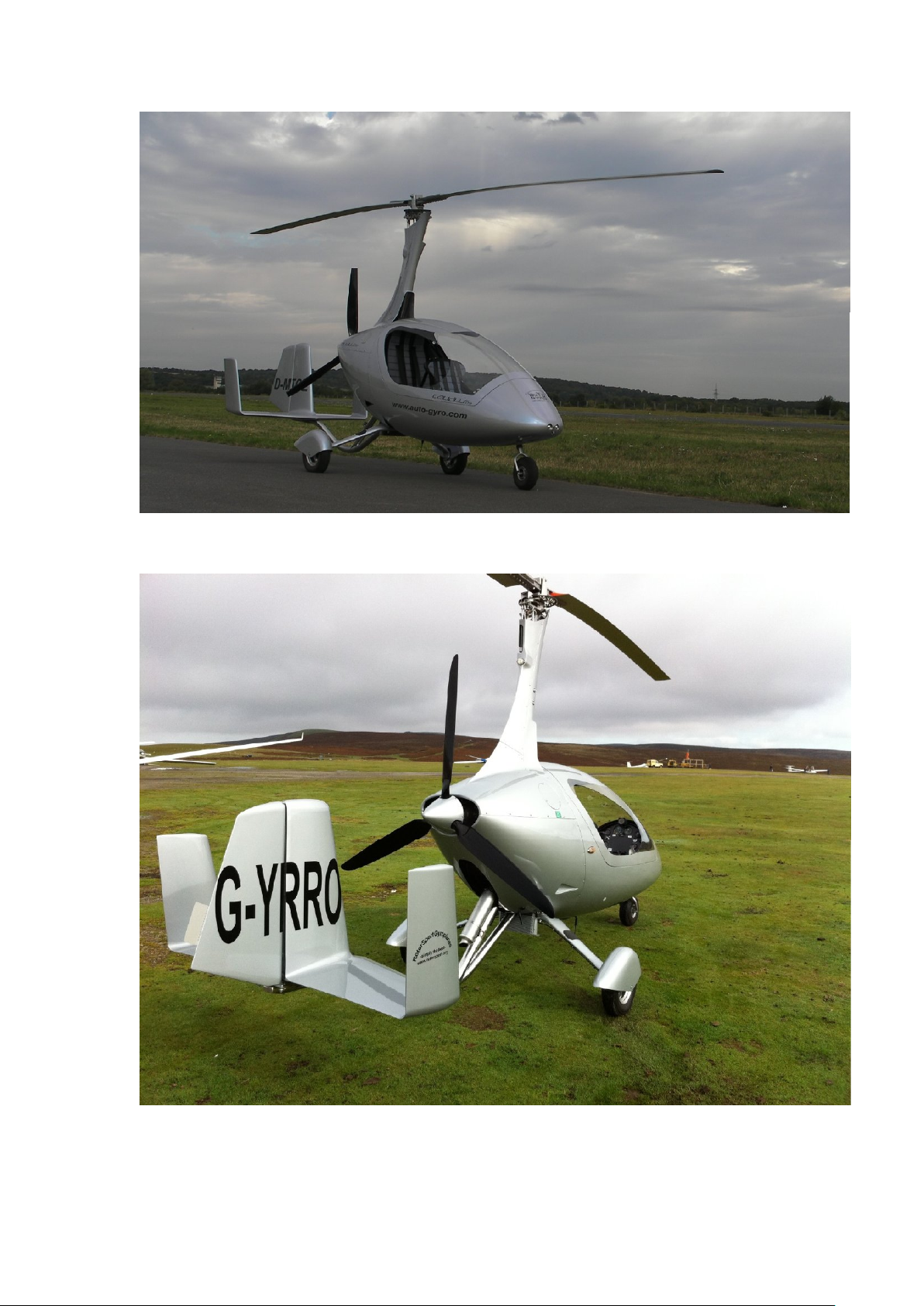
1.5 PICTORIAL VIEWS OF THE CALIDUS (figure 1, dimensions in mm)
Copyright of RotorSport UK Ltd
Document number RSUK0060
Page 11 of 101 Page issue 1, dated 14.01.11
Front quarter view
Rear quarter view
Copyright of RotorSport UK Ltd
Document number RSUK0060
Page 12 of 101 Page issue 1, dated 14.01.11
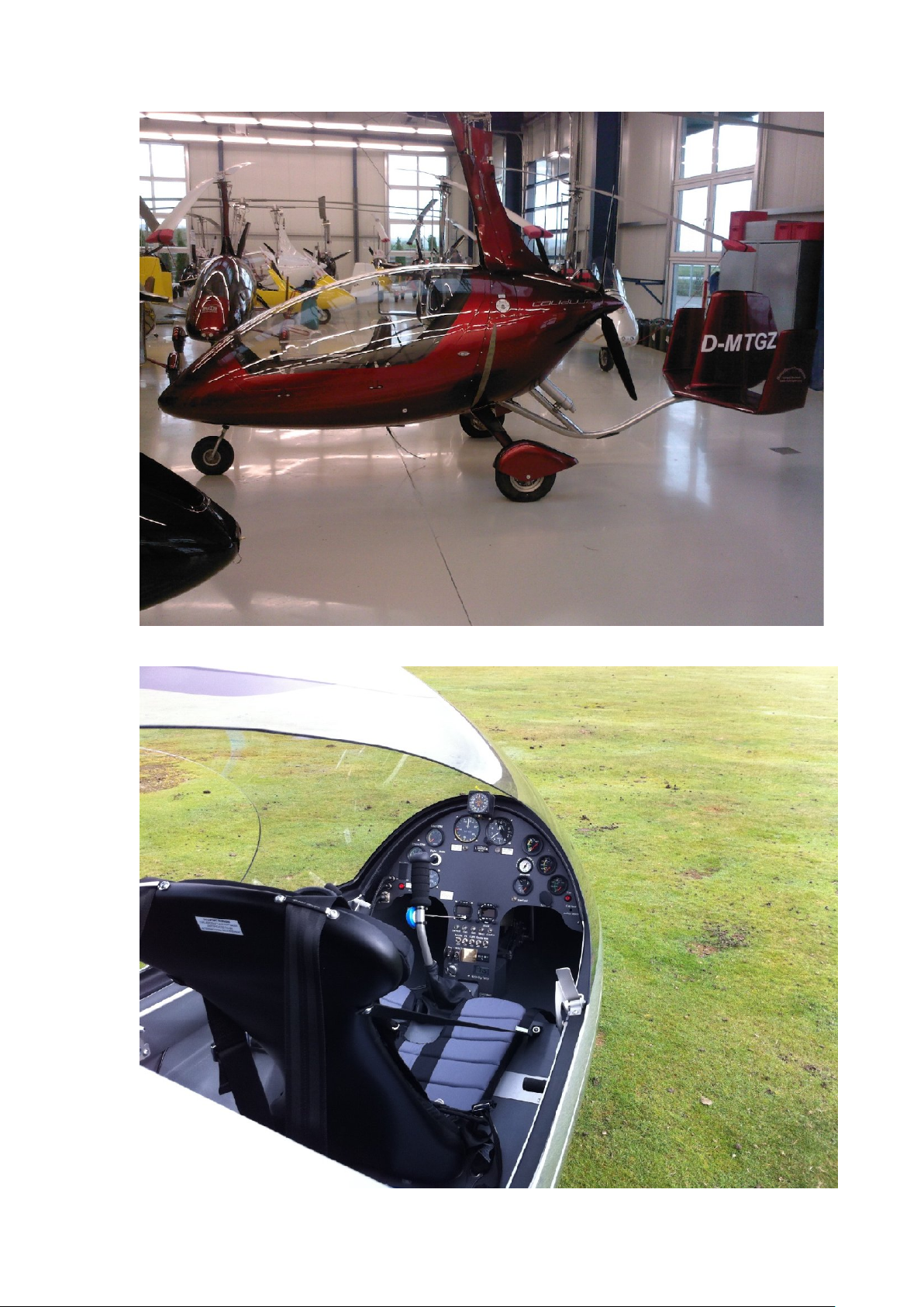
View from the side
Example cockpit view (Centre blank panel for customer GPS fitment)

Copyright of RotorSport UK Ltd
Document number RSUK0060
Page 13 of 101 Page issue 2, dated 12.9.11
Intentionally blank

Copyright of RotorSport UK Ltd
Document number RSUK0060
Page 14 of 101 Page issue 6, dated 12.04.16
2. OPERATIONAL LIMITS
2.1 INTRODUCTION
This section defines the limit values for safe operation of the Calidus autogyro. It contains
the operation limits established during flight testing, as well as limit values established by
test or computation. The existing instrument placards are described.
Recommended aircraft operational temperature limits -25 degC to +50degC.
SPECIFIC LIMITATIONS AS PER THE CAA AIRWORTHINESS AUTHORISATION
NOTICE
These limitations are mandatory, and are directly copied out below.
6. Conditions Affecting This Approval
6.1 Aerobatic Limitations
Aerobatic manoeuvres are prohibited
Manoeuvres involving a deliberate reduction in normal ‘g’ shall be avoided
6.2 Loading Limitations
Maximum Total Weight Authorised: 500kg
Maximum Empty Weight 311.6 kg (914UL) 309Kg (912ULS)
Maximum Pilot Weight front seat 125 kg
Minimum Pilot Weight front seat 65 kg
Maximum Occupant Weight rear seat 120 kg
Front seat occupants under 65 kg in weight must carry suitable ballast
6.3 Engine Limitations
Maximum take-off (max. 5 minutes) 5800 rpm
Max. continuous 5500 rpm
Max. CHT 135ºC
Min. oil temp. 50ºC
Max. oil temp. 130ºC
Min. oil pressure 0.8 bar
Normal operating range 2-5bar
Max. oil pressure 7 bar
6.4 Air Speed Limitations
Maximum indicated air speed (IAS) 90 mph,or 120mph if SB-039
incorporated, or 120mph if SB-039 incorporated and Rotor System II TOPP rotor
variant fitted (blue end caps)
6.5 Other Limitations
The aircraft shall be flown by day in visual meteorological conditions only.
Flight in icing conditions is prohibited (not placarded)
Flight in strong gusty winds or wind velocities of more than 45mph (40 kts) is
prohibited. (not placarded)

Copyright of RotorSport UK Ltd
Document number RSUK0060
Page 15 of 101 Page issue 6, dated 12.04.16
Manoeuvre Limitations
Aerobatic manoeuvres are prohibited.
Manoeuvres involving a deliberate reduction in normal ‘g’ shall be avoided.
Maximum bank angle 60 degrees from vertical
This aircraft shall be flown by day and under Visual Flight Rules only
CROSS-WIND
The maximum cross-wind component for takeoff is 22kts.
Landing should always be made into wind where practical. The maximum landing
crosswind 15kts.
Ensure you read your CAA Operational Limitations (part of the Permit to Fly) for exact
limitations of your aircraft.
2.2 AIRSPEED
The values below are indicated speeds (IAS) measured via the ASI metering hole,
centrally located in the fuselage nose.
VNE Maximum speed 90 mph, or
120mph if SB-039 incorporated
Vclimb Best climb speed 70mph
VAManoeuvre speed 80mph
VApproach Approach speed. 70mph (1st stage) 55mph (final)
VTMax speed in turbulence 70mph
Best glide speed (for maximum range) 60mph
Min rate of descent speed (min height loss) 40mph
WARNING! The maximum speed VNE must be never exceeded! Operating in excess
of this is dangerous, as this area is the safety margin to the maximum design
speed!
2.3 AIRSPEED INDICATOR MARKS
Green range (normal range) from 30-80mph
Yellow range (caution, especially nearing Vne) from 0 to 30mph, and from
80 to 90 mph
Red line (VNE) at 90 mph, or 120mph if SB-039 incorporated, or 120mph if SB-039
incorporated and Rotor System II TOPP rotor variant fitted (blue end caps)
2.4 ROTOR
Once airborne, the rotor will maintain and manage its rotational speed to match the load
exerted on it. An rpm gauge is provided to enable the pilot to easily see the rpm whilst pre
rotating and making ready for take-off, and as an in-flight monitor.
Gauge markings:
0 to 200, amber. Take care in this range, keep the stick into the wind. Allowing the wind to
get under the rotor at low rotor rpm, or leaving the stick free in windy conditions may allow
blade flap. This may damage your aircraft!
200 to 550rpm, green. Full power can be applied in take-off from 200rpm. Normal flight
range depends on loading, see 5.1, performance data.
550 to 610rpm, amber. In this range the aircraft is pulling in excess of 3G. Do not
increase G load further, reduce power and return to normal flight conditions and rotor rpm
610 rpm red line. Do not exceed. Estimated in excess of 3G loading.

Copyright of RotorSport UK Ltd
Document number RSUK0060
Page 16 of 101 Page issue 5.1, dated 10.06.14
2.5 ENGINE
Manufacturer: Bombardier Rotax, Gunskirchen/A
Type: Rotax 912 ULS or Rotax 914UL
Take-off power: 100 HP/5800 rpm (for 5 minutes max operation), 115HP/5800
for the 914UL (for 5 minutes max operation)
Continuous duty: 90 HP/5500 rpm 912ULS, 100 HP/5500rpm 914UL
Cylinder head temperature: max. 135 °C
Oil temperature: max. 130 °C
Propellers: HTC 3 blade. Pitch angle: 20.5deg 912ULS, 22deg 914UL (ground
adjustable to suit engine and working environment). Take account of the propeller
concave face whilst measuring (see maint. Manual RSUK0061). Propeller is pitched for
max ground rpm of 5500.
IVO-prop DL3-68 in-flight variable pitch propeller – see section 9
For further data refer to the engine manual and parts catalogue.
WARNING! The engine must not be run without the propeller fitted – doing so may
result in severe engine damage.
2.6 ENGINE INSTRUMENTS
The following engine values are placarded on the instruments:
Note that, other than the engine rpm, the gauges are marked with these values internally.
Range
Maximum value
Unit of
measurement
Engine RPM
Green 1600 - 5500 Amber 5500 - 5800/5min,
red line 5800.
rpm
Oil temperature
50 - 130 130 max °C
Cylinder head
temperature
to 135 135 max °C
Oil pressure
0.8bar min to 3,500
rpm, 1.5bar min
above 3,500rpm.
Normal range 2-5bar
7 (cold weather starting) Bar
2.7 WEIGHT & BALANCE
The maximum take-off weight (MTOW) of the Calidus is 500kg. Marked on the aircraft,
and on the aircraft AWC, is the actual aircraft empty weight with unusable fuel. The
Payload is the MTOW minus the empty weight, and represents the allowance available for
occupants, fuel and luggage.
If any accessories are fitted which increase the empty weight of the aircraft then the
aircraft’s maximum payload must be reduced accordingly.
The pilot is responsible for ensuring the aircraft is not flown overweight.
NOTE! Flying the aircraft overweight invalidates your Permit to Fly.
The maximum permissible positions of the centre of gravity may not be exceeded.
The centre of gravity of the aircraft type was determined during Section T Compliance
evaluation. The envelope operational extremes were evaluated and shown to be
satisfactory. However operation outside of these evaluated points is not permitted!

Copyright of RotorSport UK Ltd
Document number RSUK0060
Page 17 of 101 Page issue 2, dated 12.09.11
Evaluation recorded that the approved envelope extremes (with maximum 10kg baggage
in the rear passenger footwell) are:
Most Forward limit - 125pilot, 74Kg pass, min fuel – 485mm forward of mainwheel axle.
Most Rearwards limit - 65Kg pilot, 82Kg passenger, max fuel – 255mm forward of
mainwheel axle.
Most Highest limit - 60Kg pilot min fuel – 895mm above mainwheel axle.
Most Lowest limit - 125Kg pilot, 74Kg passenger, 15Kg fuel - 795mm above mainwheel
axle.
Vertical CG position (z) is relative to the wheel axle plane drawn between the main and
nose wheel. Longitudinal CG position (x) is fore or aft of the mainwheel axle plane
(positive forwards).
The weight and balance report (AWC) supplied with the aircraft shows the Empty Weight
and CG envelope calculated for that specific aircraft, with options supplied as new. Empty
weight means aircraft containing minimum flight accessories and minimum fuel.
The report also shows, for reference, the thrust line offset.
WARNING! Care must always be taken when flying at extremes of the operational
envelope.
Maximum occupant weight in the front seat = 125 kg
Maximum occupant weight in the rear seat (with a 65kg front seat occupant) = 120kg
Minimum occupant weight in the front seat = 65 kg
Front seat occupants under 65kg body weight must carry ballast.
Remember - Fuel loading permissible is 500kg minus occupant weight, minus aircraft
empty weight, minus any baggage or items added to the aircraft since weighed. Aircraft
empty weight is placarded. Mogas nominal density is 0.72kg/ltr (check for the type of fuel
used).
Example: 500Kg – 275Kg (empty wt) – 90Kg (rear seat occupant) – 90Kg (pilot) – 10Kg
(rear seat luggage) = 35Kg. Useful fuel load (assuming both fuel tanks fitted) is 35/0.72 =
48.6ltrs.
Maximum possible fuel load (assuming both fuel tanks fitted) is 75ltrs, 54Kg
If ballast is required to meet the minimum front seat loading condition of 65Kg, then it
should be in the form of thin lead sheet placed behind and under the pilot seat cushion.
Carrying of bags or other items inside the aircraft is possible, due to the design of the
inside construction covering the control cables and linkages.
WARNING! If carried, ensure there is no control obstruction! Bags fitted into the rear seat
must be securely attached to the seat harness, and included in the weight/balance
calculation.
This is especially important with an open canopy, take care that items inside the cockpit
do not get blown out!
WARNING! The rear seat harness must be fastened correctly around the seat in single
seat operation. DO NOT leave loose on the seat, it may entangle with the controls and
prevent correct function!
A small detachable bag may be fitted inside the aircraft. Its purpose is to carry the rotor tie
down strap and basic aircraft documents only.
Copyright of RotorSport UK Ltd
Document number RSUK0060
Page 18 of 101 Page issue 4, dated 01.07.13
2.8 FUEL
The engine manufacturer recommends unleaded gas station premium fuel (EN228
MOGAS, as allowed under GC No 3 of CAP747, accessible via the CAA website). AVGAS
100LL can be used, although not recommended for long term operation, as the lead in the
fuel causes excess plug fouling and problems with the slipper clutch – refer to the engine
manual for further information. Alternatively, unleaded aviation gasoline Avgas UL91 is
now available at some airfields and is approved for use with Rotax engines.
MOGAS should not be used if the fuel temperature exceeds 20°C or at altitudes above
6000ft due to the increased risk of vapour bubble formation in fuel lines. In these
conditions AVGAS 100LL should be used. Note: MOGAS E10 (unleaded gasoline
blended with 10% ethanol) is not approved or recommended.
Whilst refuelling:
1. Ensure that the fuel is clean and water-free.
2. Always use a filter when refuelling, preferably with a water trap
3. Ensure the aircraft keyswitch is OFF before commencing refuelling
4. Ensure filler cap properly closed (latch flush to surface) after refuelling.
5. Ensure that an earthing cable is connected, where one is available.
Before flight, use the water drain point under the keel to ensure the fuel is water free.
2.9 GENERAL PLACARDS AND MARKINGS:
In conformity with BCAR Section T the following placards and markings are installed:
- All emergency controls are coloured red.
- All cockpit controls are clearly marked as to their function and method of operation.
- Fuel and oil filler openings are clearly marked, together with the grade or type required.
- Fuel tank capacity is clearly marked.
- Loading conditions are clearly marked as follows:
- Standard placards
Loading conditions
Primary control marking
Aircraft Payload Specification
Front seat pilot: 125Kg max,
65Kg min
Pilot must carry ballast to
meet 65Kg min.
Rear seat passenger 120Kg
max
Empty weight (as measured)
Kg
MTOW 500Kg
Aircraft must only be flown
solo from the front seat.
MAX
↑
THROTTLE
CHOKE
↓
ON
BRAKE
↓
ENGAGE

Copyright of RotorSport UK Ltd
Document number RSUK0060
Page 19 of 101 Page issue 6, dated 12.04.16
Limitations if fitted with orange end-cap rotor system
Limitations if fitted with red end-cap RotorSystemII under SB-039, or SB-039 is embodied
and Rotorsystem II TOPP variant is fitted (blue end caps)
Occupant warning (both seats) Fitted beside front seat
and back of front seat
Auxiliary socket (where fitted,
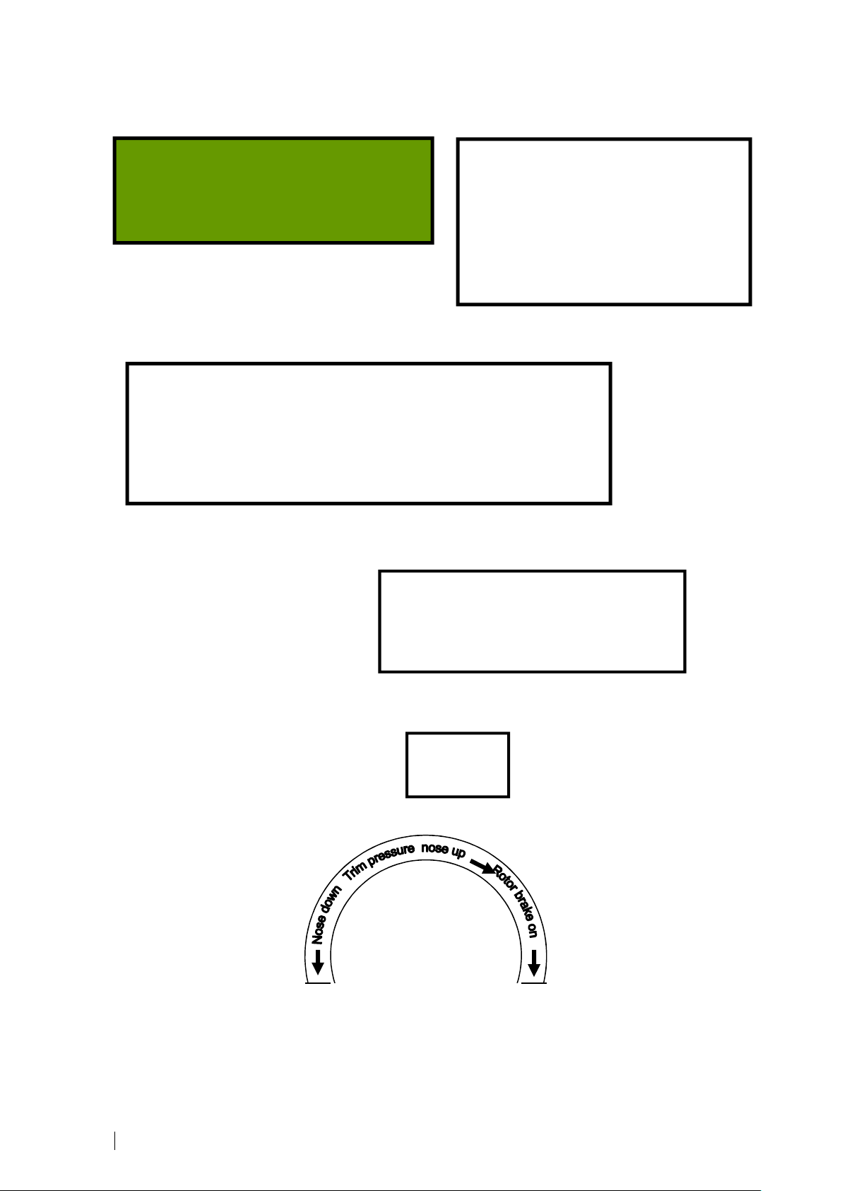
marked ‘12v 5A on the panel) Roll trim indicator (where fitted)
OPERATING LIMITATIONS
Aerobatic Limitations
Aerobatic manoeuvres are prohibited.
Manoeuvres involving a deliberate reduction in normal ‘g’ shall be avoided.
CG Range Limits (Gyroplane) – refer to Pilots Handbook data.
Airspeed Limitations
Maximum Indicated Airspeed (Vne): 90mph
Other Limitations
This aircraft shall be flown by day and under Visual Flight Rules only.
Smoking in the aircraft is prohibited
OCCUPANT WARNING
This aircraft has not been certificated to an
International Requirement
L R
Roll Trim
Front seat
back straps
limit stops
must be fitted
if rear stick is
fitted
OPERATING LIMITATIONS
Aerobatic Limitations
Aerobatic manoeuvres are prohibited.
Manoeuvres involving a deliberate reduction in normal ‘g’ shall be avoided.
CG Range Limits (Gyroplane) – refer to Pilots Handbook data.
Airspeed Limitations
Maximum Indicated Airspeed (Vne): 120mph
Other Limitations
This aircraft shall be flown by day and under Visual Flight Rules only.
Smoking in the aircraft is prohibited
Copyright of RotorSport UK Ltd
Document number RSUK0060
Page 20 of 101 Page issue 6, dated 12.04.16
Coolant header tank Engine oil tank
Fuel tank beside the filler neck (shows 39ltrs capacity if only one tank installed).
Low voltage placard mounted on instrument panel.
Warning lamp placards. (where not annotated on panel)
Pressure gauge placard
(unless panel annotated)
Fuel capacity: 75 ltrs
Preferred fuel:
EN228 MOGAS super or super plus
(AVGAS 100LL permissible)
Coolant
Header Tank
.
Filled with 50/50
water/antifreeze
Oil tank
Capacity 3 ltrs.
Use Shell VSX or
equivalent Motorcycle
oil SF or SG
Continuously lit Low Volt lamp
indicates
electrical demand exceeds supply, and
the battery is being drained. If lit in flight,
reduce demand until unlit. If not possible,
expedite landing.
Canopy
unlocked
Table of contents
Other AUTO GYRO Aircraft manuals

AUTO GYRO
AUTO GYRO CAVALON User manual

AUTO GYRO
AUTO GYRO CAVALON Owner's manual

AUTO GYRO
AUTO GYRO Cavalon Pro Owner's manual

AUTO GYRO
AUTO GYRO Cavalon Rotax 915 IS Owner's manual

AUTO GYRO
AUTO GYRO MTOsport User manual

AUTO GYRO
AUTO GYRO MTOsport User manual

AUTO GYRO
AUTO GYRO Cavalon Owner's manual

AUTO GYRO
AUTO GYRO Cavalon Owner's manual


