auto maskin SDU 404 User manual

Manual# 1100413
Installation Manual
SDU 404
Shutdown Unit

Installation Manual - SDU 404
Page ii
Installation Manual
for
SDU 404
~~~
Safety/Shutdown Unit
Revision
1.2
Revised
August 11, 2017
Revision history:
Rev.
Date
Description
1.0
19.02.16
Initial Revision (based on former QIG)
1.1
21.03.16
Added Appendix A and minor updates.
1.2
11.08.17
Added DCU 210E/208E to the DCU Communication/terminals table
Copyright © 2017 by Auto-Maskin AS.
All rights reserved. No part of this document may be reproduced or transmitted in any form or by any means,
electronic, mechanical, photocopying, recording, or otherwise, without the prior written permission of Auto-Maskin AS.

Installation Manual –SDU 404
Page iii
Table of Content
DOCUMENT INFORMATION .................................. 1
ABOUT THIS MANUAL ................................................ 1
Responsibilities ................................................1
MATCHING FIRMWARE .............................................. 1
ORDERING INFORMATION........................................... 1
SYSTEM OVERVIEW ................................................... 2
DCU 410E Engine Control Unit.........................2
RP 410/210E Remote Panel.............................2
Ethernet Switch ...............................................2
Expansion ........................................................2
INSTALLATION....................................................... 3
GENERAL ................................................................ 3
LED Overview...................................................3
WIRING .................................................................. 4
24VDC Supply ..................................................4
Switch Channels...............................................4
DCU COMMUNICATION............................................. 5
BUTTONS ................................................................ 5
Acknowledge ...................................................5
Overspeed Test ................................................5
CONFIGURATION................................................... 6
CONFIGURE SDU THROUGH THE DCU .......................... 6
Version.............................................................6
Speed Sensor ...................................................6
Switch ..............................................................6
Miscellaneous..................................................7
Output Functions .............................................7
Synchronize......................................................7
APPENDIX A - WIRING ........................................... 8
APPENDIX B - FRONT ............................................. 9

Installation Manual –SDU 404
Page 1
Document
Information
About this manual
This manual has been published
primarily for professionals and
qualified personnel.
The user of this material is assumed to
have basic knowledge in marine
systems, and must be able to carry out
related electrical work.
Warning!
Work on the low-voltage circuit should
only be carried out by qualified and
experienced personnel.
Installation or work on the shore power
equipment
must only
be carried out by
electricians authorized to work with
such installations.
Responsibilities
Warning!
It is the
sole responsibility of the
installer
to ensure that the installation
work is carried out in a satisfactorily
manner, that it is operationally in good
order, that the approved material and
accessories are used and that the
installation meet all applicable rules
and regulations.
Note! Auto-Maskin continuously
upgrades its products and
reserves the right to make
changes and improvements
without prior notice.
All information in this manual is based
upon information at the time of
printing.
For updated information, please
contact your local distributor.
Matching firmware
This version of the Manual is updated
to match the following firmware
release.
Product
Firmw.
Release
SDU 404
1.2
Oct. 2014
Ordering information
The Marine Pro covers a wide range of
compatible products within both the
200- and 400 Series. Please visit our
web site for more information.
http://auto-maskin.com/marine/

Installation Manual –SDU 404
Page 2
System Overview
The figure below shows a simple
layout with the SDU included for one
engine.
DCU 410E Engine
Control Unit
The DCU 410E engine panel is the main
building block in the 400 Series.
Engine sensor values are displayed on
the color touch screen, and commands
and other user interaction is also here.
RP 410/210E Remote
Panel
The optional RP remote panel brings
the DCU display to a remote location
with no need for any configuration.
Ethernet Switch
It’s recommended to always us an
Ethernet switch even it is possible to
use a cable only in an installation with
only one DCU and one RP. PC
connection for configuration and setup
is also more convenient with the
Ethernet switch available.
Expansion
The system can be expanded with
more input and output channels using
the versatile RIO (Remote I/O) units.

Installation Manual –SDU 404
Page 3
Installation
This chapter covers the installation of
the SDU 404.
General
The SDU 404 is an engine safety
module.
It is primarily designed to be used
together with the Marine Pro Series.
It can be installed separate from the
DCU or in the same cabinet.
The engine shutdown switches shall be
wired to the switch input channels on
the SDU.
The two-wire
SDU Link
shall be
established between the DCU and the
SDU.
LED Overview
Details regarding indicators are
described in the User’s manual but the
illustration and the following table has
a brief description:
LED
Description
Power
Lit when power supply is OK.
Flashing when below the
configurable “very low
threshold”. (Green)
Running
Lit when engine is running.
(Green)
Overspeed
Unacknowledged,
acknowledged or test mode
(Flashing/Red/Green)
Shutdown
Unacknowledged,
acknowledged.
(Flashing/Red)
Shutdown
Override
Lit when active. (Green)
Load
Reduction
Unacknowledged,
acknowledged.
(Flashing/Red)
Config
Unacknowledged,
acknowledged.
(Flashing/Amber)
MPU
MPU connected. (Green)
Unacknowledged,
acknowledged fault.
(Flashing/Amber)
ACK.
Active. (Green)
Unacknowledged,
acknowledged fault.
(Flashing/Amber)
Shutdown
Override
(Switch)
Shutdown override active.
(Green)
Fault (Amber).
SW 1-4
Unacknowledged,
acknowledged
shutdown/load reduction
(Flashing/Red).
Unacknowledged,
acknowledged fault. (Amber)

Installation Manual –SDU 404
Page 4
Wiring
Follow these wiring guidelines.
24VDC Supply
Connect 24VDC to terminals 1
(positive) and 2 (0V). Connect a ground
connection to terminal 3.
Wire Requirement
SDU supply wires shall have a minimum
area of 1.0 mm2.
Switch Channels
Switch Channels are configurable for
loop monitoring and short circuit.
All switch channels use a two-wire
layout, where both wires from the
switch are to be routed to the SDU.
Wire Requirement
Switch wires shall have a minimum area
of 0.5 mm2.
Broken Wire Detection
Requirement for type approved
installations. Each switch shall have a
10k resistor connected across.
Note! The 10k resistors shall be
connected directly
at the switch
,
and not at the SDU 404.
Switches shall be normally open (NO),
and shall close to indicate engine
shutdown.
Short Circuit Detection
Each switch shall have a 10k resistor
connected in series.
Note! The 10k resistors shall be
connected directly
at the switch
,
and not at the SDU 404.
Pickup Channel
The SDU can operate with a magnetic
or active pickup source.
Connect the pickup to terminals 4 and
5, with shield to terminal 3.
Note! Make sure the cable shield is
connected at the SDU side and
not at the pickup side.
Shutdown Override
This is to be wired exactly like a Switch
Input, that is; it shall be a normally
open switch. Close the switch to
activate Shutdown Override.
Note! Make sure a 10k resistor is
connected across the switch.

Installation Manual –SDU 404
Page 5
DCU Communication
Depending on the DCU model connect
the wires in the shielded communication
cable to the terminals as shown in the
table below:
SDU 404
DCU
410(E)/
408
DCU
210E/
208E
DCU
210/
208
28 ( )
60 ( )
22 ( )
29 (L)
61 (L)
5 (L)
23 (L)
30 (H)
62 (H)
6 (H)
24 (H)
Note! Do not connect the
cable shield ( ) at both ends.
When properly connected, the DCU will
find the SDU automatically. To start
using the SDU, enable it via the DCU
web interface.
The SDU Link shall be terminated with
120 ohm resistors in both ends. The
DCU is terminated internally.
Connections
The two-wire
SDU Link
has fixed
communication parameters.
The Baud rate is 19200 baud.
8 data bits
1 stop bit
Even parity
Configuration Mismatch
Warning
When the SDU is connected to the DCU,
the DCU will analyze the configuration
in the SDU and compare it to the stored
configuration in the DCU. If these do
not match, the DCU will give a
“Configuration Mismatch” warning.
The warning can be acknowledged, but
DCU login rights are required to reset
this warning. With login rights, the
configuration can be copied from the
DCU to the SDU, or vice versa.
Please see the relevant Marine Pro
manual for further details.
Buttons
Acknowledge
This button is used to acknowledge
alarms and faults. See User’s Manual
for more details.
Overspeed Test
Press and hold the “Overspeed Test”
button for more than two seconds to
enter the overspeed test mode. See
User’s Manual for more details.

Installation Manual –SDU 404
Page 6
Configuration
Configure SDU through
the DCU
The easiest and preferred method of
configuring the SDU is to login to the
DCU via the web interface.
When logged in, enter the SDU section
and configure the SDU.
Next, from the menu on the left, select
the sub-section to be configured.
Press the Submit button after each
configuration change.
Note! The configuration is stored in the
DCU’s current
active configuration
file
. If a new SDU is connected to
the DCU the configuration is
transferred to the SDU when it is
connected.
For more configuration information,
please consult the Marine Pro 400E
Series Configuration Manual.
Version
This page give the information about
the hardware and software version of
the SDU 404.
Speed Sensor
This page has the configuration of the
pickup channel.
Switch
This page has the configuration for
each of the four switch channels.
Type
Select the type of short circuit and
broken wire detection.
Type 1.
Short circuit and broken wire detection.
A 10k resistor to be connected in
series and a 10k resistor to be
connected in parallel over the switch.
Type 2.
Broken wire detection. Minimum
requirement for type approved
installations.
A 10k resistor to be connected in
parallel over the switch.
Type 3.
No fault detection.
Event
Select the event (Shutdown and/or
Load Reduction) that will be activated
when the switch is closed.
On Run Only
Enable this if the event shall be enabled
only when the engine is running.
This is typical for all pressure channels.

Installation Manual –SDU 404
Page 7
Shutdown Override Disabled
Enable this if the event shall be
triggered even if SDU is in shutdown
override state.
This is typical for a manual E-stop
button.
Delay before Load Reduction
Set the number of seconds until load
reduction.
Delay before Shutdown
Set the number of seconds until
shutdown.
Initial Delay
Set the number of seconds until switch
channel is activated for monitoring.
The “Initial Delay” countdown starts
when all criteria (“Engine is running”
and “Speed Limit”) are met.
Speed Limit Enabled
Set if Speed limit is enabled or not. The
actual engine speed is set in the Speed
limit [RPM] section.
Speed Limit [RPM]
If the engine speed is above the
set value, then the channel is
enabled.
If the engine speed drops 50
RPM below the set value, then
the channel is disabled.
Miscellaneous
Set input voltage warning levels.
Enable “Allow Load Reduction
Override” to override load
reductions via the shutdown
override switch.
Enable “Automatic Buzzer Off” to
make the SDU buzzer silence
automatically after five seconds.
“Shutdown Override Switch” and
“Acknowledge Switch”
configuration.
Output Functions
Configuration of relays and digital
output.
Synchronize
Synchronization of DCU and SDU
configuration.

Installation Manual –SDU 404
Page 8
Appendix A - Wiring
The diagram below shows recommended wiring including 3 different types of Switch
inputs.
Installation Manual –SDU 404
Page 9
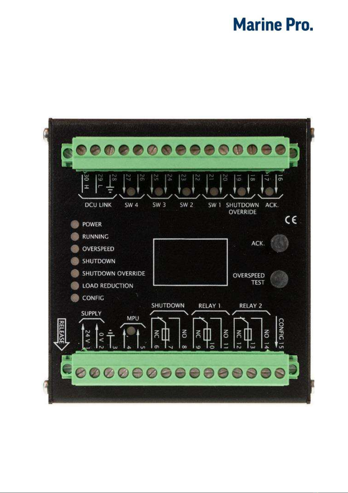
Appendix B - Front
Front side and Connectors
DCU Link
Switch input 1-4
Shutdown
Override
Acknowledge
Power Supply
MPU Input
Shutdown
Relay 1&2
Config.
Other manuals for SDU 404
1
Table of contents
Popular Switch manuals by other brands


ifs
ifs POC2502 Series user manual

Vixel
Vixel InSpeed 335 Installation & configuration guide

HPE
HPE FlexFabric 5940 SERIES Command reference

Intermatic
Intermatic GM40AVE-RD89 Series installation instructions

3Com
3Com IntelliJack NJ200 Software guide

Hirschmann
Hirschmann RS2-4R Description and operating instructions

Ruijie Networks
Ruijie Networks RG-S12006 Hardware installation and reference guide

Magnavox
Magnavox MWV2053T manual

Siemens
Siemens SIRIUS 3SE7141-1EG10 operating instructions

Alcatel-Lucent
Alcatel-Lucent OmniStack 6200 Brochure & specs

Insignia
Insignia NS-PH3A4AP Quick setup guide

Ross
Ross carbonite Configuration guide