Bulletin AFS 460137.03 2
Specifications
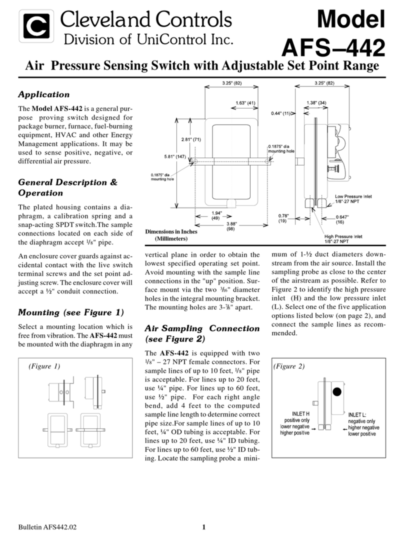
Model AFS–460–137 Air
Pressure Sensing Switch with
manual reset feature, DPDT
contact arrangement , for 24 VAC
applications.
Sample Media: Air or
combustion products that do not
degrade silicone.
Mounting Position (in order to
meet lowest operating
specifications): Diaphragm in any
vertical plane.
Field Adjustable Range:
0.40 ± .06"w.c. to 12.0"w.c.
Switch Differential: Progressive,
increasing from approximately
.06± .01"w.c. at minimum set
point, to approximately .8"w.c. at
maximum set point.
Maximum Pressure:
0.5 psi (0.03 bar)
Operating Temperature Range:
-40 to 180F (-40 to 82C)
Electrical Rating:
0.5 VA @ 24 V AC, 50/60 Hz.
Contacts:
DPDT, 2 form-C
rated 8 amp @ 250 V AC.
Electrical Connections:
Screw terminals.
Sample Line Connections:
Ferrule and nut compression type
connectors will accept .25" OD
rigid tubing.
Shipping Weight: 1.2 lbs.
Agency Approvals: pending
Accessories
•P/N 18311 Slip-on ¼" OD Tubing Adapter,
suitable for slipping on flexible plastic
tubing. • Sample line probes. • Orifice
plugs (pulsation dampers).
Pressure Conversion Table
1" H2O = .0361 lbs./sq. in. or .0735 in. mercury
1" Hg. = .491 lbs./sq. in. or 13.6 in. water
1 psi = 27.7 in. water or 2.036 in. mercury
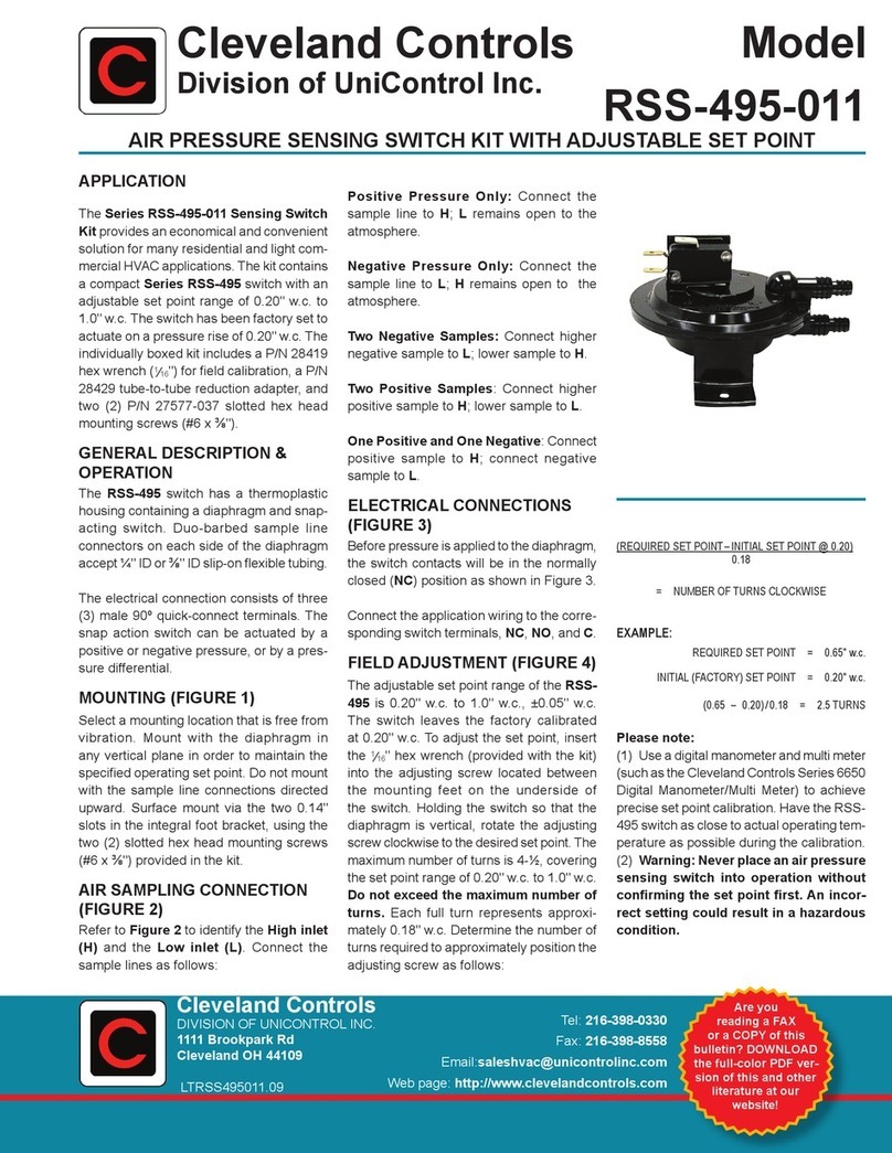
POSITIVE PRESSURE ONLY: Con-
nect the sample line to inlet H; inlet L
remains open to the atmosphere.
NEGATIVE PRESSURE ONLY: Con-
nect the sample line to inlet L; inlet H
remains open to the atmosphere.
TWO NEGATIVE SAMPLES: Con-
nect the higher negative sample to inlet
L. Connect the lower negative sample
to inlet H.
TWO POSITIVE SAMPLES: Con-
nect the higher positive sample to inlet
H. Connect the lower positive sample
to inlet L.
ONE POSITIVE AND ONE NEGA-
TIVE SAMPLE: Connect the positive
sample to inlet H. Connect the negative
sample to inlet L.
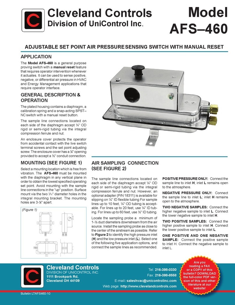
Electrical Connections
(see Figure 3)
Before pressure is applied to the dia-
phragm, the snap switch contacts will be
in the normally closed (NC) position.
As differential pressure rises above the
field adjustable set point, the snap
switch opens, de-energizing the coil on
the slave relay, which activates the
DPDT contacts. An LED indicates that
the snap switch exceeds differential set
point. It remains lit until the manual re-
set push button is depressed.
Field Adjustment
The AFS-460–137 Manual Reset Air
Switch has an adjustment range of 0.40
to 12.0" w.c., ±.06" w.c. To adjust the
set point:
Turn the adjusting screw counterclock-
wise until motion has stopped. Next,
turn the adjusting screw 4 complete
turns in a clockwise direction to engage
the spring. From this point, the next ten
turns will be used for the actual cali-
bration. Each full turn represents ap-
proximately 1.16" w.c.
Please note: To properly calibrate an
air switch, a digital manometer or other
measuring device should be used to
confirm the actual set point.
C
NC MANUAL
RESET
HIGH
PRESS
LOW
PRESS
H
K1
CONVERTER
NC1
NO 1 C1
NC2NO 2 C2
Shown in "on shelf " condition:
no power and no differential
pressure applied.
Note that when power is applied across
H and N :
1) Relay K1 is energized
2) Contacts change state (i.e., NO contact
closes and NC contact opens)
3) LED is illuminated when differential
pressure exceeds set point.
TB2 #1
24 V AC
TB2 #2
COMMON
