Automatic Heating AHGR410AW Series Quick guide

Edition 1.0
AHGR410AW DC Inverter Heat Pump
Installation and Instruction Manual

2

Inverter Air Source Heat Pump (AHGR410AW) - Installation and Instruction Manual
Contents
1. Preface .........................................................................................4
2. Safety Precautions......................................................................5
2. Signs nd Symbols used in this Mnul................................................................................................... 5
2.2 Wrning........................................................................................................................................................... 5
2.3 Attention..........................................................................................................................................................
3. General Information....................................................................7
3. Het Pump Appernce nd Structure....................................................................................................
3.2 Euipment Fetures.....................................................................................................................................
3.3 Specifictions................................................................................................................................................. 8
3.4 Drwings nd Dimensions ..........................................................................................................................
4. Installation .................................................................................11
4. Schemtic Digrm for Air-conditioning...............................................................................................
4.2 Euipment Selection & Sizing ..................................................................................................................
4.3 nstlltion onditions............................................................................................................................... 2
4.4 Mchine Foundtion ...................................................................................................................................2
4.5 Wter Loop onnection.............................................................................................................................. 2
4. Power Supply onnection ......................................................................................................................... 2
4. Positioning the Unit.....................................................................................................................................3
4.8 Trnsit............................................................................................................................................................3
4. Tril Run ........................................................................................................................................................3
5. Control & Operation ..................................................................14
5.. Min nterfce Disply nd Function.....................................................................................................4
5.2 Usge of Wired ontroller......................................................................................................................... 5
6. Troubleshooting ........................................................................18
. Electronic ontrol Fult Tble.................................................................................................................. 8
.2 Freuency onversion Bord Fult Tble.............................................................................................
.3 Prmeter List.............................................................................................................................................
.4 Euipment Fult Tble ...............................................................................................................................2
7. Main Controller Terminals .......................................................21
. ontroller nterfce Digrm nd Lbels ............................................................................................. 2
8. Appendix ....................................................................................22
8. Appendix – nstlltion Schemtic Digrm (Expndble Wter Tnk).....................................22
8.2 Appendix 2 – nstlltion of the Automtic Fill-wter Vlve.............................................................23
8.3 Appendix 3 – nstlltion of the Lekge Pressure Vlve................................................................. 23
8.4 Appendix 4 – Assistnt Het Sources ....................................................................................................23
8.5 Appendix 5 - ution & Wrning..............................................................................................................24
8. Appendix - ble specifictions ...........................................................................................................24
Contents
3

Inverter Air Source Heat Pump (AHGR410AW) - Installation and Instruction Manual
01. Preface
1. Preface
Thank you for purchasing AHGR410AW Series – DC Inverter Heat Pump
from Automatic Heating Global Pty Ltd.
In order to provide customers with a high-quality, reliable, and versatile product, this heat
pump was produced in accordance with strict design and manufacturing standards. This
manual includes all necessary information about installation, handling, maintenance, and
troubleshooting. Please read this manual thoroughly before using the unit. The manufacturer
will not be held liable in case of damages or injuries resulting from improper installation,
handling, maintenance, and troubleshooting that is not in accordance with this manual.
The unit must be installed only by qualified personnel.
The warranty provided is subject to the following
conditions:
• The unit must only be installed, opened, or repaired
by a qualified installer or an authorized dealer.
• Maintenance and operation must be carried out
according to the recommended procedures and
frequency stated in this manual.
• Use genuine standard spare parts only.
Failure to comply with these conditions will
invalidate the warranty.
AHGR410AW Series – DC Inverter Heat Pump is an
ecient, energy-saving, and ecofriendly heat pump
that is suitable for space heating and domestic hot
water production.
By providing hot/warm water, it can work with any
kind of indoor units including fan coils, radiators,
and floor heating pipes, which can all be connected
to a single monobloc unit. This equipment is
designed to allow heat recovery via a super heater
that could generate hot water for sanitary and
other purposes.
This series of DC Inverter Heat Pumps has the
following features:
Advanced Control
The micro-processor controller can be used to
easily check or set the running parameters of the
heat pump. The centralized control system can also
be used to control several units via PC.
Smart Appearance and Easy to Install
The heat pump is designed for visual appeal as
well as ease of installation. A monobloc unit has
a water pump already included, which makes it
compact and also very easy to install.
Quiet Operation
This device uses high quality and ecient
compressor, fan, and water pump that ensure low
noise level during operation.
Ecient Heat Exchange
This equipment uses a specially-designed heat
exchanger that is ecient, helping you save
more energy.
Reliable
This device was built to work even under extreme
working conditions. It can work under an ambient
temperature as low as -15ºC for heating.
4

Inverter Air Source Heat Pump (AHGR410AW) - Installation and Instruction Manual 02. Safety Precautions
2. Safety Precautions
To prevent accidents and avoid damage to property and personal injury, please
read and understand this manual carefully.
Installation
Operation
Warning
Incorrect operation may lead to death or
serious injuries.
Prohibited
The action identified is prohibited.
Mandatory
The action identified is mandatory.
Installer must be professionally trained.
The heat pump must be installed by a
qualified and professionally-trained
personnel to avoid incorrect installation
which could lead to water leakage, electrical
shock, or fire.
Keep fingers away from fans.
Do not insert fingers or any other objects into
the fans or evaporator of the unit as this could
result in injury and/or equipment damage.
Provide proper grounding.
Make sure that the unit and power
connection have good grounding / earthing
to avoid the risk of electrical shock.
Shut down the unit in case
of emergency.
If you notice something wrong in the unit or
if it gives o a strange smell, shut it down
immediately by disconnecting the power
supply. Continuing to run the unit may cause
an electrical short circuit or fire.
Attention
Incorrect operation may cause minor harm to
people or material damages and/or losses.
2.1 Signs and Symbols used in this Manual
2.2 Warning
Moving and Repairing
Entrust the moving and re-installation of
the unit to qualified personnel.
If the unit needs to be moved and be re-
installed, please contact a qualified person
or company to carry it out for you. Improper
installation may lead to water leakage,
electrical shock, personal injury, or fire.
Entrust the repair of the unit
to qualified personnel.
If the unit needs to be repaired, please
contact a qualified person or company to
carry it out for you. Improper installation
may lead to water leakage, electrical shock,
personal injury, or fire.
Do not repair the equipment
on your own.
Unless you are professionally trained and
suitably qualified, do not attempt to repair
or work on the unit as this could result in
electrical shock, fire, or other accidents.
5

Inverter Air Source Heat Pump (AHGR410AW) - Installation and Instruction Manual
02. Safety Precautions
2.3 Attention
Installation Operation
Keep away from flammable substances.
DO NOT install the unit near flammable
gases or substances. Leakage of these may
cause fire.
Check the baseplate /
foundation regularly.
Inspect the baseplate or foundation of the
equipment at least once every month to
avoid any decline or damage.
Switch o the power during
maintenance.
Please switch o the power when cleaning
the equipment or during maintenance
Provide appropriate machine foundation.
Make sure that the unit is securely positioned
and that its base is strong enough to prevent
it from falling.
Provide a circuit breaker.
Provide an appropriate and properly-sized
circuit breaker for the unit. Lack of circuit
breaker could lead to electrical shock or fire.
Do not use copper or iron as fuse.
It is prohibited to use copper or iron as fuse.
The appropriate fuse for the equipment must
be selected and installed by an electrician.
Do not spray flammable gas to the unit.
DO NOT spray flammable gas to the heat
pump to avoid fire.
6

Inverter Air Source Heat Pump (AHGR410AW) - Installation and Instruction Manual 03. General Info
3.1 Heat Pump Appearance and Structure
3.2 Equipment Features
3. General Information
Air outlet in
horizontal direction
Remote Controller
(Manually)
The longest distance of installing
the remote controlleris 200 meters.
Water Outlet Tube
Water Inlet Tube
Air outlet in
horizontal direction
Remote Controller
(Manually)
The longest distance of installing
the remote controlleris 200 meters.
Water Outlet Tube
Water Inlet Tube
AHGR410AW6 / AHGR410AW10
AHGR410AW17 / AHGR410AW25
Plate Heat Exchangers
The equipment uses SWEP heat exchangers that
are compact yet highly ecient.
Eco-friendly Refrigerant
The equipment uses the new generation of eco-
friendly refrigerant, R410, which is harmless to the
ozone layer.
Wide Operating Temperature Range
The equipment is designed to function normally
even at harsh conditions and ambient temperatures
as low as -15ºC.
The water-cooling system will be opened
automatically to guarantee the normal operation
of cooling when the ambient temperature is higher
than 30ºC.
7

Inverter Air Source Heat Pump (AHGR410AW) - Installation and Instruction Manual
03. General Info
3.3 Specifications
Model AHGR410AW6 AHGR410AW10 AHGR410AW17 AHGR410AW25
Cooling Capacity kW 5.4 10 14.5 20
BTU/h 18426 34121 49489 68260
Heating Capacity kW 6.4 11.5 16.5 25
BTU/h 21838 39240 56315 85325
Hot Water Capacity kW 7.3 13.2 21.6 30
BTU/h 24909 45040 73702 102364
Cooling Power Input kW 1.9 3.4 5.6 9.0
Heating Power Input kW 2.0 3.4 5.1 9.0
Hot Water Power Input kW 2.1 3.6 6.2 8.2
Operation Electric Current (Max) A 8.7 15.7 27 14.0
Cooling Capacity Range kW 1.6~5.4 2.0~10 5.0~14.5 7.0~20.0
Heating Capacity Range kW 1.9~6.4 2.5~11.5 5.0~16.5 8.0~25.0
Hot Water Capacity Range kW 3.0~7.3 4.2~13.2 7.4~21.6 11.0~30.0
Cooling Power Input Range kW 0.6~1.9 1.0~3.4 1.6~5.6 2.5~9.0
Heating Power Input Range kW 0.6~2.0 0.8~3.4 1.2~5.1 2.5~9.0
Hot Water Power Input Range kW 0.7~2.1 1.0~3.6 1.5~6.2 2.1~8.2
Power Supply 230V~/50Hz 230V~/50Hz 230V~/50Hz 380V/3N~/50Hz
Compressor Quantity 1 1 1 1
Compressor Model Rotary Rotary Rotary Rotary
Fan Quantity 1 1 2 2
Fan Power Input W 75 75 75×2 150×2
Fan Rotational Speed RPM 850 850 850 900
Noise dB(A) 54 54 58 62
Water Pump Input kW 0.05 0.18 0.5 0.65
Water Head m 6.2 12.5 21 22.5
Water Connection inch 1 1 1 1/4 1 1/4
Water Flow Volume m /h3 1.0 1.6 2.8 4.2
Water Pressure Drop (Max) kPa 10 24 105 71
Unit Net Dimensions (L/W/H) mm 1008*463*790 953*445*910 996*395*1320 1175*400*1592
Unit Shipping Dimensions (L/W/H) mm 1060*500*805 1040*490*920 1070*435*1340 1225*430*1600
Net Weight kg See nameplate
Shipping Weight kg See package label
Cooling Working Conditions: (DB/WB) 35º/24º, (Outlet/Inlet) 7º/12º
Heating Working Conditions: (DB/WB) 7º/6º. (Outlet/Inlet) 35º/30º
Hot Water Working Conditions: (DB/WB) 20º/15º. (Outlet/Inlet) 40º/45º.
BS EN 14511-1-2013
8

Inverter Air Source Heat Pump (AHGR410AW) - Installation and Instruction Manual 03. General Info
3.4 Drawings and Dimensions
AHGR410AW6
AHGR410AW10
9

Inverter Air Source Heat Pump (AHGR410AW) - Installation and Instruction Manual
03. General Info
3.4 Drawings and Dimensions (continued)
AHGR410AW17
AHGR410AW25
10

Inverter Air Source Heat Pump (AHGR410AW) - Installation and Instruction Manual 04. Installation
4.1 Schematic Diagram for Air-conditioning
4.2 Equipment Selection & Sizing
4. Installation
Considering local climate conditions, space
restrictions, and insulation level, calculate the
required cooling (heating) capacity per square
meter. Compute the total capacity needed for the
whole area.
Then choose the suitable heat pump's model,
considering their temperature requirements
and outputs specified below:
Cooling Only Unit
Chilled water outlet temperature: 5-15ºC
Maximum ambient temperature: 43ºC
Heating and Cooling unit
Cooling chilled water outlet temperature: 5-15ºC
Maximum ambient temperature: 43ºC
Heating unit
Warm water inlet temperature: 40-50ºC
Minimum ambient temperature: -10ºC
Inverter air source heat pumps are generally used
in houses, oces, hotels, and other establishments
that need heating or cooling in dierent areas and
that need to be controlled separately.
Connecting Hose
Water Pump
Non-Return Valve
Temperature Meter
Three-Way Valve
Expansion Tank
Pressure Dierential Bypass Valve
Automatic Refill Valve
General Valve
Y-Type Filter
Pressure Meter
Vent Valve
Safety Valve
Heat Pump
Inlet
Buer Tank
Second Floor
First Floor
City
Water
To City Water
Outlet
11

Inverter Air Source Heat Pump (AHGR410AW) - Installation and Instruction Manual
04. Installation
4.3 Installation Conditions
4.4 Machine Foundation
4.5 Water Loop Connection
4.6 Power Supply Connection
• The unit can be installed on any area outdoors such
as terrace, rooftop, and ground as long as it can
carry heavy machinery.
• The location must have good ventilation.
• The place must be free from direct heat and flames.
• A shelter is needed in winter to protect the
equipment if exposed to snow.
• There must be no obstacles near the air inlet and
outlet of the heat pump.
• There must be an available water channel around
the equipment to drain the condensing water.
• The area must be protected from strong winds.
• There must be enough space around the unit for
maintenance.
The heat pump can be installed onto a concrete base by expansion
screws, or onto a steel frame with rubber feet that can be placed on the
ground or rooftop. Make sure that the unit is placed horizontally.
Please consider the following when installing the water pipe connection:
• Try to reduce the resistance on the water through the piping.
• The piping must be clean and free from dirt and debris. Water leakage test must be
carried out before insulating to ensure that there will be no water leaking.
• Pipe pressure must be tested separately. DO NOT test it together with the heat pump.
• There must be an expansion tank at the top point of the water loop, and the water level
in the tank must be at least 0.5 meters higher than the top point of the water loop.
• The flow switch must be installed inside the heat pump. Ensure that the wiring and
action of the switch is normal and controlled by the controller.
• Avoid air staying inside of the water pipe. There must be an air vent at the top point of
the water loop.
• There must be a thermometer and a pressure gauge at the water inlet and outlet for
easy inspection during operation.
• Open the front panel, then open the power supply access.
• The power supply must go through the wire access and be connected to the power
supply terminals in the controlling box. Then connect the 3-signal wire plugs of the
wire controller and main controller.
• If the outside water pump is needed, please insert the power supply wire into the
wire access as well and connect to the water pump terminals.
• If an additional auxiliary heater is needed to be controlled by the heat pump
controller, the relay (or power) of the auxiliary heater must be connected to the
relevant output of the controller.
12

Inverter Air Source Heat Pump (AHGR410AW) - Installation and Instruction Manual 04. Installation
4.7 Positioning the Unit
4.8 Transit
Barrier
Barrier
Barrier
Barrier
Air Inlet
A B
Air Outlet
Maintenance Space
D
C
The picture shows the location of horizontal air outlet unit.
Attention
Requirements
A > 500mm
B > 1500mm
C > 1000mm
D > 500mm
Warning
DO NOT touch the heat exchanger of the heat
pump with your bare hands or other objects!
Minimum ventilation
distance
During transport, please keep the unit in an upright position.
If the unit needs to be hung during installation, an 8-meter cable is
needed, and there must be a soft material between the cable and the
unit to prevent damage to the heat pump cabinet. (See picture 1)
Picture 1
4.9 Trial Run
Inspection before the Trial Run Trial Run
• Check the indoor unit and make sure that the pipe
connection is correctly installed and the relevant
valves are open.
• Check the water loop and ensure that the water
inside the expansion tank is enough, that the water
supply is good, and that the water loop is full of
water without any air. Also make sure that the
water pipe is well-insulated.
• Check the electrical wiring. Make sure that
the power voltage is normal, that the screws
are fastened, that the wiring is connected in
accordance with the diagram, and that the earthing
is connected.
• Check the heat pump unit including all of the
screws and parts of the unit to see if they are in
good order. Upon powering on, review the indicator
on the controller to see if there is any failure
indication. The pressure gauge can be connected to
the check valve to see the pressure of the system
during the trial run.
• Start the heat pump by pressing key on the
controller. Check if the water pump is running. If it is
running normally, there should be a reading of 0.2
MPa on the pressure meter.
• After the water pump runs for 1 minute, the
compressor will start. Listen if there is a strange
sound from the compressor. If an abnormal sound
occurs, please stop the unit immediately and check
the compressor. Otherwise if the compressor is
running normally, please look at the pressure meter
of the refrigerant.
• Then check whether the power input and running
current is in line with the manual. If not, please stop
and check.
• Adjust the valves on the water loop to make sure
that the hot (or cold) water supply through each door
is good and meets the requirement of heating (or
cooling).
• Check if the outlet water temperature is stable.
• The parameters of the controller are set by the
factory. The user is not allowed to change them on
their own.
13

Inverter Air Source Heat Pump (AHGR410AW) - Installation and Instruction Manual
05. Control & Operation
5.1. Main Interface Display and Function
5. Control & Operation
1 2 3 4 5 6
7
109
8
Name Function
1 On/O Switch ON and OFF.
Red indicates ON, while grey indicates OFF.
2 Mode
Hot water mode, heating mode, cooling mode, hot
water+heating mode, or hot water+cooling mode can
be selected
3 Temp. Setting Sets the target temperature
4 Fast heating Starts rapid heating.
This key will be displayed during heating.
5 Timer Setting Set the timer. White indicates “disabled”, while green
indicates “enabled”.
6 Setup Check the status of the unit, time, factory parameter,
temperature curve, timer setting, and mute setting.
7 Fault
This icon will flash whenever there is an error.
The display will enter Failure Record Interface upon
tapping this icon.
8 Defrost Machine is in defrosting mode when this icon is shown
9Hot Water Mode Machine is in hot water mode when this icon is shown
10 Cooling Mode Machine is in cooling mode when this icon is shown
Key Functions
1. Power On Interface 2. Starting Up Interface
Note: The controller can display the temperature in ºF or ºC
depending on the unit model.
14

Inverter Air Source Heat Pump (AHGR410AW) - Installation and Instruction Manual 05. Control & Operation
5.2 Usage of Wired Controller
1. During shutdown, On/O key will be in gray color.
Pressing On/O key will start up the machine.
2. During startup, On/O key will be in red color.
Pressing On/O key will shut down the machine.
Mode Function
1Hot Water Advance to hot water mode interface;
2 Heating Advance to heating mode interface;
3 Cooling Advance to cooling mode interface;
4 Hot Water + Heating Advance to hot water + heating mode interface;
5 Hot Water + Cooling Advance to hot water + cooling mode interface;
Name Function
1 Back Goes back to main interface
2Hot Water Temp Target temperature of hot water can be set via a
pop-up keyboard
3Cold Water Temp Target temperature of cold water can be set via a
pop-up keyboard
Key Function
1Current Temp. Shows current temperature
2 Return Return back to the main interface
3 Delete Undo the last action
4 Enter Save your target temperature and will return
back to the main interface
1. On/O
3. Temperature Setting
2. Mode
There are five modes that can be selected in the
interface upon clicking the Mode key:
Note: If the unit you have purchased is a heating-only model (without
cooling function), cooling mode will not be available and will not be
shown on the interface.
Hot Water + Cooling Mode Example When the target temp. is being set, an onscreen keyboard will pop-up
1
2
3
1
2
3
4
15

Inverter Air Source Heat Pump (AHGR410AW) - Installation and Instruction Manual
05. Control & Operation
4. Fast Heating
Clicking the fast heating key will lead you to the
screen as shown.
5. Timer Setting
1
1
2 3
2
3
4
6
5
7
Clicking the timer setting key, enters the timer
setting interface as shown.
Key Function
1 Return Return to the main interface
2Timed Startup
(Green ON / Grey OFF) Start or turn o the timed start-up function
3Timed Shutdown
(Red ON / Grey OFF) Start or turn o the timed start-up function
4Hour Indicator
of Timed Startup Indicates the hour for a timed start-up
5Minute Indicator
of Timed Startup Indicates the minute for a timed start-up
6Hour Indicator of
Timed Shutdown Indicates the hour for a timed shutdown
7Hour Indicator of
Timed Shutdown Indicates the minute for a timed shutdown
Key Function
1 Fast Heating Will trigger the above interface to appear
2 Start Starts fast heating
3 Stop Stops fast heating
In the above picture: Assuming that the unit is operating unmanned,
the equipment will start automatically at 17:10 and will shut down at
20:10.
6. Setup
2
1
5
3
4
6
Click the setup key to enter the setup interface
Key Function
1 Return Return to the main interface
2 Operating Mode View the current operating parameters of the unit
3 Mute Enable the mute function
4 Factory Parameter Enter the password to enter the factory parameter
settings and status parameters interface
5System Time Setting Set the system time
6 Curve View the temperature curve
Tapping operating mode key (2) will show the above interface;
16

Inverter Air Source Heat Pump (AHGR410AW) - Installation and Instruction Manual 05. Control & Operation
7. Failure Record Interface
1 2 3
4
Upon clicking the fault icon on the main interface,
the following display will be shown:
Key Function
1 Return Return to the main interface
2 Up Increase the value
3 Down Decrease the value
4 Cancel Cancel the current settings and return to the settings page
5 Enter Enters the current settings
Key Function
1 Auto Enable auto mode
2 Mute Enable mute mode
3 Powerful Enable powerful mode
Key Function
1 Fault Code Shows fault code
2 Fault Description Provides info about the fault
3 Fault Date/Time Indicates when the fault occured:
Day-month-year, hour: minute
4 Clear Fault Clears all fault logs
6. Setup (continued)
1 2 3
Tapping the mute key (3) will show the above interface;Tapping the system time setting key (5) will show the above interface
1
2
3
4 5
8. Color Display Calibration
Keep clicking quickly at any blank area on the
interface until you hear a long beep. This will
trigger the calibration interface to open. Click
“+” to start the calibration. Once you hear the
beep again, the calibration is finished and will
automatically exit.
17

Inverter Air Source Heat Pump (AHGR410AW) - Installation and Instruction Manual
06. Troubleshooting
6.1 Electronic Control Fault Table
6. Troubleshooting
You can refer to the malfunction table below to find out the failure cause & solution
Protect/fault Fault Code Reason Elimination methods
Inlet Temp. Sensor Fault P01 The temp. sensor is broken or short circuit Check or change the temp. Sensor
Outlet Temp. Sensor Fault P02 The temp. sensor is broken or short circuit Check or change the temp. Sensor
Water Tank Temp. Sensor Fault P03 The temp. sensor is broken or short circuit Check or change the temp. sensor
AT Sensor Fault P04 The temp. sensor is broken or short circuit Check or change the temp. sensor
Suction Temp. Sensor Fault P17 The temp. sensor is broken or short circuit Check or change the temp. sensor
Coil Temp. Sensor Fault P153 The temp. sensor is broken or short circuit Check or change the temp. sensor
Exhaust Temp. Sensor Fault P181 The temp. sensor is broken or short circuit Check or change the temp. sensor
Exhaust Overtemperature P182 The temp. sensor is broken or short circuit Check or change the temp. sensor
Suction Pressure Sensor Fault PP2 The pressure sensor is broken Check or change the pressure sensor
Exhaust Pressure Sensor Fault PP1 The pressure sensor is broken Check or change the pressure sensor
Low AT protection TP The environment temp. is low
Electric Overheat Protection E04 The compressor is overloaded Check whether the system of the
compressor is running normally
Communication Fault E08 Communication failure between
wire controller and mainboard
Check the wire connection between
remote wire controller and main board
HP Protection E11 The high-pressure switch is broken Check the pressure switch and cold circuit
LP Protection E12 The low-pressure switch is broken Check the pressure switch and cold circuit
Primary Anti-freezing Protection E19 The ambient temp. Is low
Secondary Anti-freezing Protection E29 The ambient temp. Is low
Flow Switch Protection E032 No water / insucient water in water system Check the pipe water flow and water pump
Compressor Overcurrent
Shutdown Fault E051 The compressor is overload Check whether the system of the
compressor running normally
Anti-freezing Protection E171 Water flow is not enough Check the pipe water flow and check
whether the water system is jammed or not
DC Fan Motor 1 Failure F031
1. Motor is in locked-rotor state
2.The wire connection between DC-fan motor module
and fan motor is in bad contact
1.Change fan motor
2.Check the wire connection and make sure they are
in good contact
DC Fan Motor 2 Failure F032
1. Motor is in locked-rotor state
2.The wire connection between DC-fan motor module
and fan motor is in bad contact
1.Change fan motor
2.Check the wire connection and make sure they are
in good contact
DC Fan Motor
Communication Failure E081 Speed control module and main
board communication failure Check the communication connection
18

Inverter Air Source Heat Pump (AHGR410AW) - Installation and Instruction Manual 06. Troubleshooting
You can refer to the malfunction table below to find out the failure cause & solution
6.2 Frequency Conversion Board Fault Table
6.3 Parameter List
Protect/fault Fault Code Reason Elimination methods
IPM Overcurrent Shutdown Fault F00 IPM input current is large Check and adjust the current measurement
Compressor Activation Failure F01 Lack of phase/step or drive hardware damage Check the measuring voltage
Check frequency conversion board hardware
PFC Fault F03 PFC circuit protection Check the PFC switch tube if short circuit or not
DC Bus Overload F05 DC bus voltage > DC bus over-voltage protection value Check the input voltage measurement
DC Bus Underload F06 DC bus voltage < DC bus over-voltage protection value Check the input voltage measurement
AC Input Underload F07 The input voltage is low, causing the input current to be low Check the input voltage measurement
AC Input Overload F08 The input voltage is too high, more than outage
protection current RMS Check the input voltage measurement
Input Voltage Sample Fault F09 The input voltage sampling fault Check and adjust the current measurement
Communication Failure
between DSP and PFC F10 DSP and PFC connection fault Check the communication connection
Communication Fault (DSP) F11 DSP and main board communication failure Check the communication connection
Communication Fault (Inverter
Board) F12 Frequency conversion board and main
board communication failure
Check the wire connection between remote
inverter board and main board
IPM Overheat Stop F13 The IPM module is overheating Check and adjust the current measurement
Weak Magnetism Alarm F14 Compressor magnetic force is not enough
Input Voltage Lacking Phase F15 The input voltage underwent phase-loss Check and measure the voltage adjustment
IPM Current Sample Fault F16 IPM sampling electricity is faulty Check and adjust the current measurement
Sensor Fault of Module/Radiator F17 The transducer is overheating Check and adjust the current measurement
IGBT Power Device Overheat Alarm F20 The transducer is overheating Check and adjust the current measurement
Overload Alarm F21 Compressor input current is too large Check and adjust the current measurement
AC Input Overcurrent Alarm F22 Compressor input current is too large Check and adjust the current measurement
EEPROM Fault Alarm F23 MCU error
Destroyed EEPROM
Activation Ban Alarm F24 MCU error
LP 15V Underload Fault F25 The V15V is either overloaded or has low voltage Check the V15V input voltage if in range
13.5V~16.5V or not
IGBT Power Device Overheat Fault F26 Transducer temperature is too high Check and adjust the current measurement
Meaning Default Remarks
Cooling target temperature set point 12ºC Adjustable
Heating target temperature set point 40ºC Adjustable
19

Inverter Air Source Heat Pump (AHGR410AW) - Installation and Instruction Manual
06. Troubleshooting
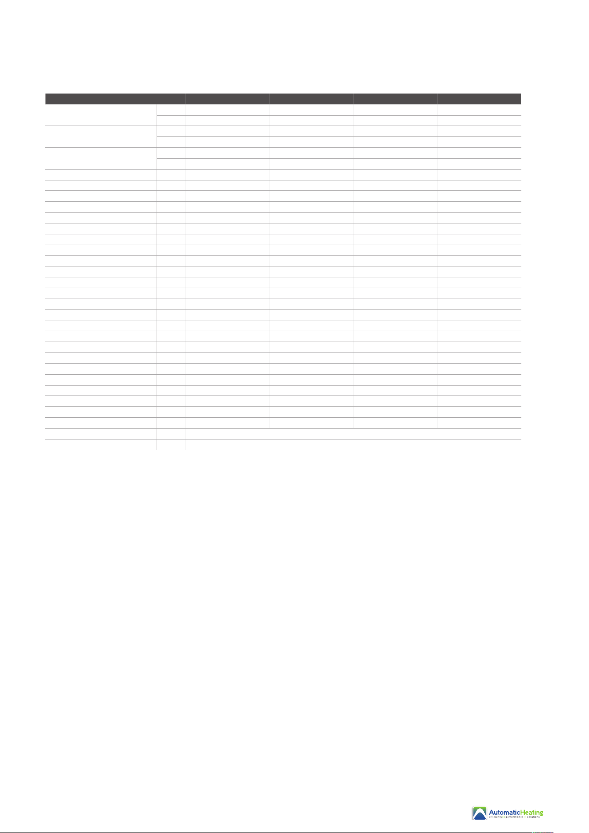
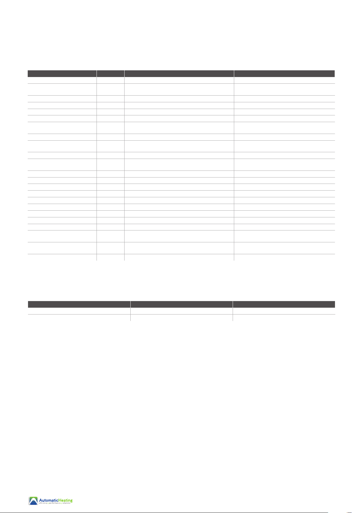
6.4 Equipment Fault Table
Failure Possible causes for the failure Solutions
Heat pump cannot be started • Incompatible power supply
• Power supply cable is loose
• Circuit breaker is open
• Shut o the power and check the power supply.
• Check the power cable and fix the connection.
• Check for the cause and replace the fuse or circuit
breaker.
Water pump is running with
high noise or without water
• Lack of water in the piping
• Too much air in the water loop
• Water valves are closed
• Dirt or blockage on the water filter
• Check the water supply & charge water into the piping.
• Discharge the air from the water loop.
• Open the valves in the water loop.
• Clean the water filter.
Heat pump capacity is low;
compressor does not stop
• Lack in refrigerant
• Bad insulation on water pipe
• Low heat exchange rate on air side exchanger
• Lack of water flow
• Check for gas leakage and recharge the refrigerant.
• Fix the insulation on the water pipe.
• Clean the air side heat exchanger.
• Clean the water filter.
High compressor exhaust • Too much refrigerant
• Low heat exchange rate on air side exchanger
• Discharge the redundant gas.
• Clean the air side heat exchanger.
Low pressure problem of the system • Lack of gas
• Blockage on filter or capillary
• Lack of water flow
• Check for gas leakage and recharge Freon.
• Replace filter or capillary.
• Clean the water filter and discharge the air from
the water loop.
Compressor does not run • Power supply failure
• Compressor contactor is broken
• Power cable is loose
• Protection on compressor
• Wrong setting on return water temp.
• Lack of water flow
• Check the power supply.
• Replace the compressor contactor.
• Tighten the power cable.
• Check the compressor exhaust temp.
• Reset the return water temp.
• Clean the water filter and discharge the air from
the water loop.
High noise from the compressor • Liquid refrigerant goes into the compressor
• Compressor failure
• Bad evaporation; check the cause for bad evaporation
and get rid of this.
• Change the compressor.
Fan does not run • Failure on fan relay
• Fan motor is broken
• Replace fan relay.
• Replace fan motor.
The compressor runs but heat pump
does not have heating or cooling
capacity
• No gas in the heat pump
• Heat exchanger is broken
• Compressor failure
• Check for system leakage and recharge refrigerant.
• Find out the cause and replace the heat exchanger.
• Replace compressor.
Low outlet water temperature • Low water flow rate
• Low setting on the desired water temp.
• Clean the water filter & discharge air from the water loop.
• Reset the desired water temperature.
Low water flow protection • Lack of water in the system
• Failure on flow switch
• Clean the water filter & discharge air from the water loop.
• Replace the flow switch.
You can refer to the malfunction table below to find out the failure cause & solution
20
This manual suits for next models
4
Table of contents
Other Automatic Heating Heat Pump manuals
Popular Heat Pump manuals by other brands

Ameristar
Ameristar A4HP6018A1000B Installer's guide

NCP
NCP 1000 Series installation guide

Ferroli
Ferroli DIAMANT S Series Use and maintenance manual

Nulite
Nulite NE-C3BZ-B2F Installation and operation instruction

Trane
Trane TTD installation manual

Vaillant
Vaillant UK aroTHERM plus Schematics and Installation Guide