AUTOMATION24 O1D215 User manual

Operating instructions
Optical distance sensor
O1D215
706172 / 00 08 / 2012
UK

2
Contents
1 Preliminary note���������������������������������������������������������������������������������������������������4
1�1 Symbols used ������������������������������������������������������������������������������������������������4
1�2 Warning signs used ���������������������������������������������������������������������������������������4
2 Safety instructions �����������������������������������������������������������������������������������������������4
3 Functions and features ����������������������������������������������������������������������������������������6
3�1 Application areas �������������������������������������������������������������������������������������������6
4 Modes������������������������������������������������������������������������������������������������������������������6
4�1 Hysteresis function mode ������������������������������������������������������������������������������6
4�2 Window function mode ����������������������������������������������������������������������������������6
4�3 Analogue function mode ��������������������������������������������������������������������������������6
5 Installation������������������������������������������������������������������������������������������������������������7
5�1 Installation conditions ������������������������������������������������������������������������������������7
5�2 Mounting accessories������������������������������������������������������������������������������������7
6 Electrical connection��������������������������������������������������������������������������������������������8
7 Operating and display elements ��������������������������������������������������������������������������9
8 Menu������������������������������������������������������������������������������������������������������������������10
8�1 Menu structure���������������������������������������������������������������������������������������������10
8�2 Explanation of the menu������������������������������������������������������������������������������ 11
9 Parameter setting ����������������������������������������������������������������������������������������������13
9�1 General parameter setting���������������������������������������������������������������������������13
9�1�1 Setting a parameter value ������������������������������������������������������������������13
9�1�2 Change from menu level 1 to menu level 2 ����������������������������������������14
9�1�3 Electronic lock ������������������������������������������������������������������������������������14
9�2 Configuration of the basic settings ��������������������������������������������������������������15
9�2�1 Selection of the display unit����������������������������������������������������������������15
9�2�2 Setting the display ������������������������������������������������������������������������������15
9�2�3 Configure OUT1 ���������������������������������������������������������������������������������15
9�2�4 Hysteresis function �����������������������������������������������������������������������������16
9�2�5 Setting of the switch point for hysteresis function OUT1 ��������������������17
9�2�6 Window function ���������������������������������������������������������������������������������17
9�2�7 Setting of the switch points for window function OUT1 ����������������������18
9�2�8 Configure OUT2 ���������������������������������������������������������������������������������19

3
UK
9�2�9 Setting of the switch point for hysteresis function OUT2 ��������������������19
9�2�10 Setting of the switch points for window function OUT2 ��������������������19
9�2�11 Scaling of the measuring range (analogue output)���������������������������19
9�3 Teach mode �������������������������������������������������������������������������������������������������21
9�3�1 Setting of the sampling rate����������������������������������������������������������������21
9�3�2 Setting of the repeatability ������������������������������������������������������������������21
9�3�3 Table repeatability and accuracy ��������������������������������������������������������22
9�4 Extended functions ��������������������������������������������������������������������������������������22
9�4�1 Setting of the delay time for switching outputs �����������������������������������22
9�4�2 Setting of the damping of the measured signal ����������������������������������23
9�4�3 Reset all parameters to factory setting �����������������������������������������������23
9�4�4 Display of the software version number ���������������������������������������������23
10 Operation���������������������������������������������������������������������������������������������������������23
10�1 Set-up ��������������������������������������������������������������������������������������������������������23
10�1�1 Error indications��������������������������������������������������������������������������������23
10�2 Operating modes ���������������������������������������������������������������������������������������24
10�2�1 Run mode �����������������������������������������������������������������������������������������24
10�2�2 Display mode������������������������������������������������������������������������������������24
10�2�3 Programming mode ��������������������������������������������������������������������������25
11 Maintenance, repair, disposal ��������������������������������������������������������������������������25
12 Scale drawing ��������������������������������������������������������������������������������������������������26
13 Factory setting �������������������������������������������������������������������������������������������������27
4
1 Preliminary note
1.1 Symbols used
►Instruction
> Reaction, result
[…] Designation of pushbuttons, buttons or indications
→Cross-reference
Important note
Non-compliance can result in malfunction or interference�
Information
Supplementary note�
Note laser class
1.2 Warning signs used
WARNING
Warning of serious personal injury�
Death or serious irreversible injuries may result�
2 Safety instructions
• Please read this document prior to set-up of the unit� Ensure that the product is
suitable for your application without any restrictions�
• Improper or non-intended use may lead to malfunctions of the unit or to unwan-
ted effects in your application� That is why installation, electrical connection,
set-up, operation and maintenance of the unit must only be carried out by
qualified personnel authorised by the machine operator�
• In case of malfunction of the unit please contact the manufacturer� If the unit is
tampered with and/or modified, any liability and warranty is excluded�
5
UK
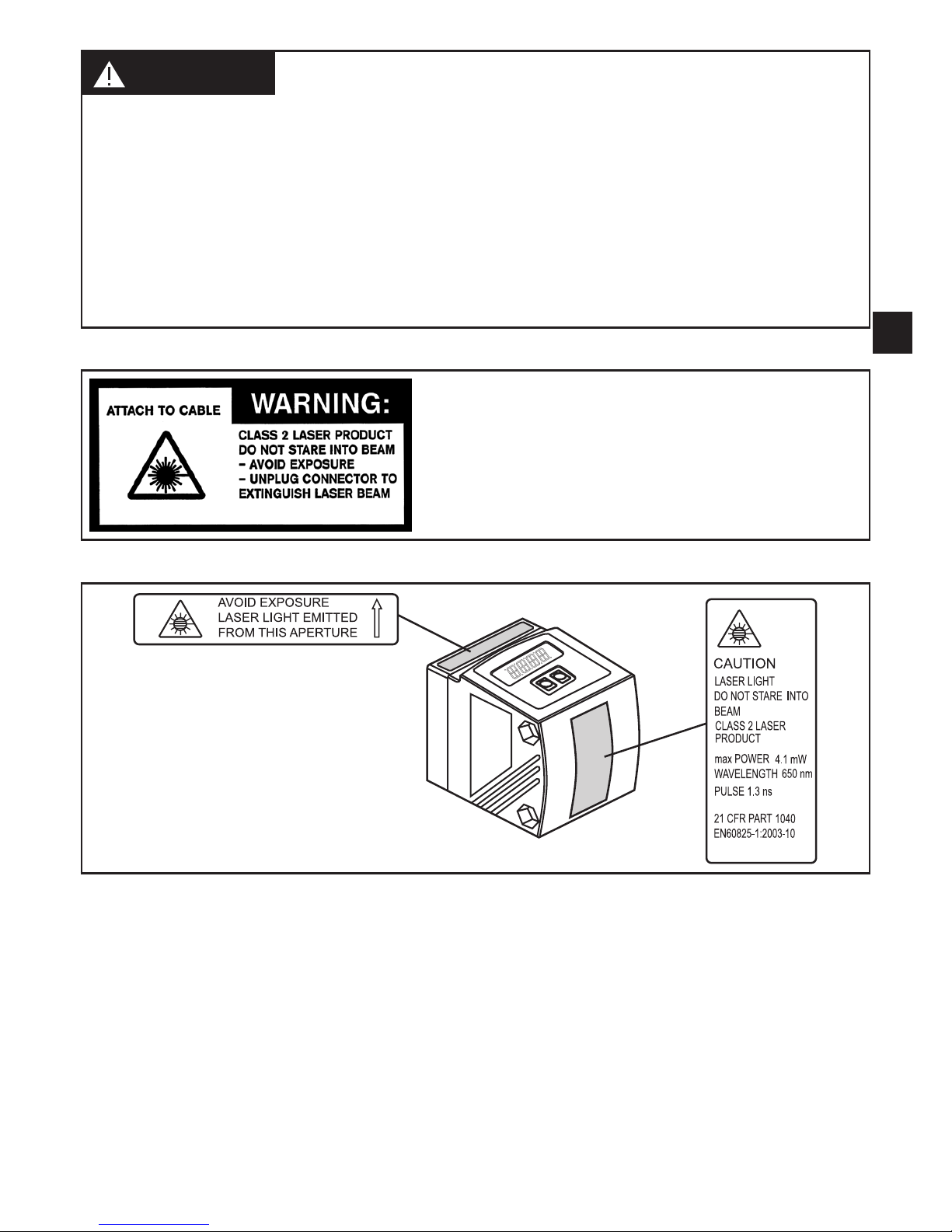
WARNING
Visible laser light; laser protection class 2�
Use of controls or adjustments other than those specified herein may result in hazardous
radiation exposure� Damage to the retina is possible�
►Do not stare into the laser beam!
►Apply the enclosed labels (laser warning) in the immediate vicinity of the unit�
►Adhere to the caution and warning notes on the product label�
►Use the enclosed label for the power supply cable�
Label for supply cable
Product label

6
3 Functions and features
The unit is used as an optical distance sensor�
3.1 Application areas
• The optical distance sensor measures distances between 0�2���10 m�
• It has a background suppression at >10���100 m�
• The measured value is shown in a 10-segment display�
• Two output signals can be generated depending on the set output function�
The distance between the sensor and the background must be limited to
max� 100 m by the customer� Otherwise measured values can be ambi-
guous.→5.1Installationconditions
4 Modes
4.1 Hysteresis function mode
The hysteresis keeps the switching state of the output stable if the measured
value varies about the sensing range� Both outputs (OUT1 and OUT2) can be set
ashysteresisfunction.→9.2.4Hysteresisfunction
4.2 Window function mode
The window function enables the monitoring of a defined acceptable range� Both
outputs(OUT1andOUT2)canbesetaswindowfunction.→9.2.6Window
function
4.3 Analogue function mode
An analogue signal, which is proportional to the distance, can be provided at out-
put2(OUT2).→9.2.11Scalingofthemeasuringrange(analogueoutput).

7
UK
5 Installation
5.1 Installation conditions
►Install the unit so that the object to be detected is within a measuring range of
0�2���10 m�
The unambiguity range of the sensor is fixed to 100 m� Objects within a range >
10���100 m are suppressed�
Reflecting objects in the direct beam path of the sensor - also in the ran-
ge > 100 m – are to be avoided by the customer� Otherwise the measured
values can be ambiguous�
5.2 Mounting accessories
The unit is supplied without mounting accessories�
Examples of mounting accessories Ord. no.
Mounting set O1D (for rod mounting Ø 12 mm) 100121
Mounting rod straight Ø 12 mm / M10 100122
Protective cover O1D 100124
1
2
Example mounting:
1: Mounting set for rod Ø 12 mm
Ord� no� 100121
2: Mounting rod straight Ø 12 mm / M10
Ord� no� 100122
8
6 Electrical connection
The unit must be connected by a qualified electrician�
►The national and international regulations for the installation of electrical
equipment must be adhered to�
►Ensure voltage supply to EN 50178, SELV, PELV�
►Disconnect power�
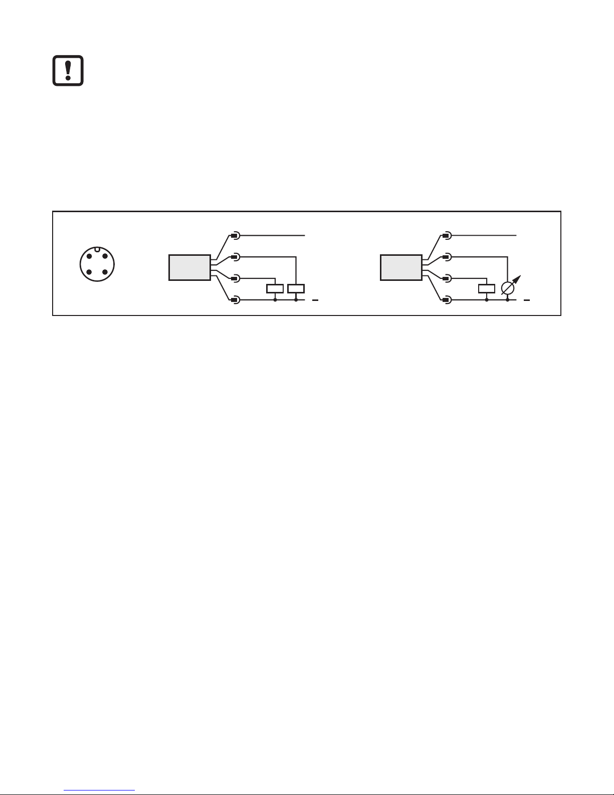
►Connect the unit as follows:
DC PNP
43
2 1
Core colours:
1 = BN (brown), 2 = WH (white), 3 = BU (blue), 4 = BK (black)

9
UK
7 Operating and display elements
1: 4 x LED green Lighting LED = power and set display unit (mm, m, inch)
2: 4 x LED yellow
(two not con-
nected)
Indication of the switching state; lights, if the corresponding
output is switched�
3: 4-digit alphanume-
ric display
Indication of the measured distance, the parameters and para-
meter values�
4: Programming
button [SET]
Setting of the parameter values (scrolling by holding pressed;
press briefly to increment)�
5: Programming
button [MODE/
ENTER]
Selection of the parameters and acknowledgement of the para-
meter values�

10
8 Menu
8.1 Menu structure
= [MODE / ENTER] = [SET]

11
UK
8.2 Explanation of the menu
Forthefactorysettingspleaserefertotheendoftheseinstructions(→13Factory
setting)�
Configuration for output 1
4 switching functions can be selected:
[Hno],[Hnc],[Fno],[Fnc]→9.2.3ConfigureOUT1
Switch point for hysteresis function OUT1
Limit value at which the output with selected hysteresis function changes
its switching state (object nearer / farther than distance set)�
[SP1] is only active if [OU1] = [Hno] or [Hnc]�
→9.2.5SettingoftheswitchpointforhysteresisfunctionOUT1
Switch points for window function OUT1
Limit values at which the output with selected window function changes its
switching state (object present / not present between the distance "near"
and the distance "far")�
[nSP1] = switch point "near" / [FSP1] = switch point "far"�
[nSP1] / [FSP1] are only active if [OU1] = [Fno] or [Fnc]�
→9.2.7SettingoftheswitchpointsforwindowfunctionOUT1
Configuration for output 2
4 switching functions and 2 analogue signals can be selected:
[Hno],[Hnc],[Fno],[Fnc],[I],[U]→9.2.8ConfigureOUT2
Switch point for hysteresis function OUT2
Limit value at which the output with selected hysteresis function changes
its switching state (object nearer / farther than distance set)�
[SP2] is only active if [OU2] = [Hno] or [Hnc]�
→9.2.9SettingoftheswitchpointforhysteresisfunctionOUT2
Switch points for window function OUT2
Limit values at which the output with selected window function changes its
switching state (object present / not present between the distance "near"
and the distance "far")�
[nSP2] = switch point "near" / [FSP2] = switch point "far"�
[nSP2] / [FSP2] are only active if [OU2] = [Fno] or [Fnc]�
→9.2.10SettingoftheswitchpointsforwindowfunctionOUT2
Analogue start point
Measured value at which 4 mA / 0 V are provided�
[ASP] is only active if [OU2] = [I] or [U]�
→9.2.11Scalingofthemeasuringrange(analogueoutput)
12
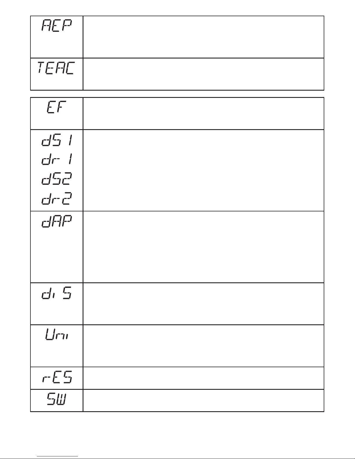
Analogue end point
Measured value at which 20 mA / 10 V are provided�
[AEP] is only active if [OU2] = [I] or [U]�
→9.2.11Scalingofthemeasuringrange(analogueoutput)
Teach mode
Selection "sampling rate" or "repeatability"
→9.3Teachmode
Extended functions
Press [SET] to open the submenu "Extended functions"
→9.4.Extendedfunctions
Delay for the switching outputs
[dSx] = switch-on delay; [drx] = switch-off delay�
The output does not immediately change its switching state when the
switching condition is met but only after the delay has elapsed� If the swit-
ching condition is no longer met after the delay has elapsed, the switching
state of the output does not change�
[dS2] and [dr2] are not effective if [OU2] = [I] or [U]�
→9.4.1Settingofthetimedelayforswitchingoutputs
Damping of the measured signal
This function allows to suppress short-time saturation of the measuring
element (such saturation can result from direct reflection or strong fluctu-
ations in brightness)�
During the set delay time, the latest valid value measured is displayed,
the output signals remain unchanged�
→9.4.2Settingofthedampingofthemeasuredsignal
Setting of the display
7 settings can be selected:
[d1], [d2], [d3], [rd1], [rd2], [rd3], [OFF]
→9.2.2Settingthedisplay
Setting of the display unit
Selection of the unit of measurement for [SP1], [SP2], [ASP], [AEP]
Options: [mm] [m] [inch]
→9.2.1Selectionofthedisplayunit
Restore the factory setting
→9.4.2Resetofallparameterstofactorysetting
Display of the software version number
→9.4.4Displayofthesoftwareversionnumber

13
UK
9 Parameter setting
During parameter setting the unit remains internally in the operating mode� It
continues its monitoring function with the existing parameters until the change has
been completed�
9.1 General parameter setting
9.1.1 Setting a parameter value
Set the display unit [Uni] before the values for the parameters are defined�
In case of subsequent changes of the display unit rounding errors during
internalconversiontootherunitsmayfalsifythesetvalues.→9.2.1
Selection of the display unit�
1
Selection of the parameter
►Press [MODE/ENTER] until the reque-
sted parameter is displayed�
2
Setting of the parameter value
►Press [SET] and keep it pressed�
> The current parameter value flashes
for 5 s�
►Increase the setting value step by step
by pressing the button once or continu-
ously by holding it down�
Decrease the value: let the display move to the maximum setting value� Then the
cycle starts again at the minimum setting value�
3
Confirmation of the parameter
value
►Press [MODE/ENTER] briefly�
> The parameter is displayed again; the
new parameter value is effective�
4Setting of other parameters
►Start again with step 1�
5
Finish parameter setting
►Wait for 15 s or press [MODE/ENTER]�
> The current measured value is displayed�

14
9.1.2 Change from menu level 1 to menu level 2
►Press [MODE/ENTER] several times until
[EF] is displayed.
►Press [SET] briefly�
> The first parameter of the submenu is
displayed (here:[dr1])�
9.1.3 Electronic lock
The unit can be locked electronically to prevent unauthorised setting� On delivery
the unit is not locked�
Locking
►Make sure that the unit is in the normal
operating mode�
►Keep [MODE/ENTER] + [SET] pressed
until [Loc] is displayed�
> The unit is locked�
[Loc] is displayed briefly if you try to change parameter values on the locked unit during
operation�
Unlocking
►Keep [MODE/ENTER] + [SET] pressed
until [uLoc] is displayed�
> The unit is unlocked�
Timeout
If no button is pressed for 15 s during the setting procedure, the unit returns to the
Run mode with unchanged values�
15
UK
9.2 Configuration of the basic settings
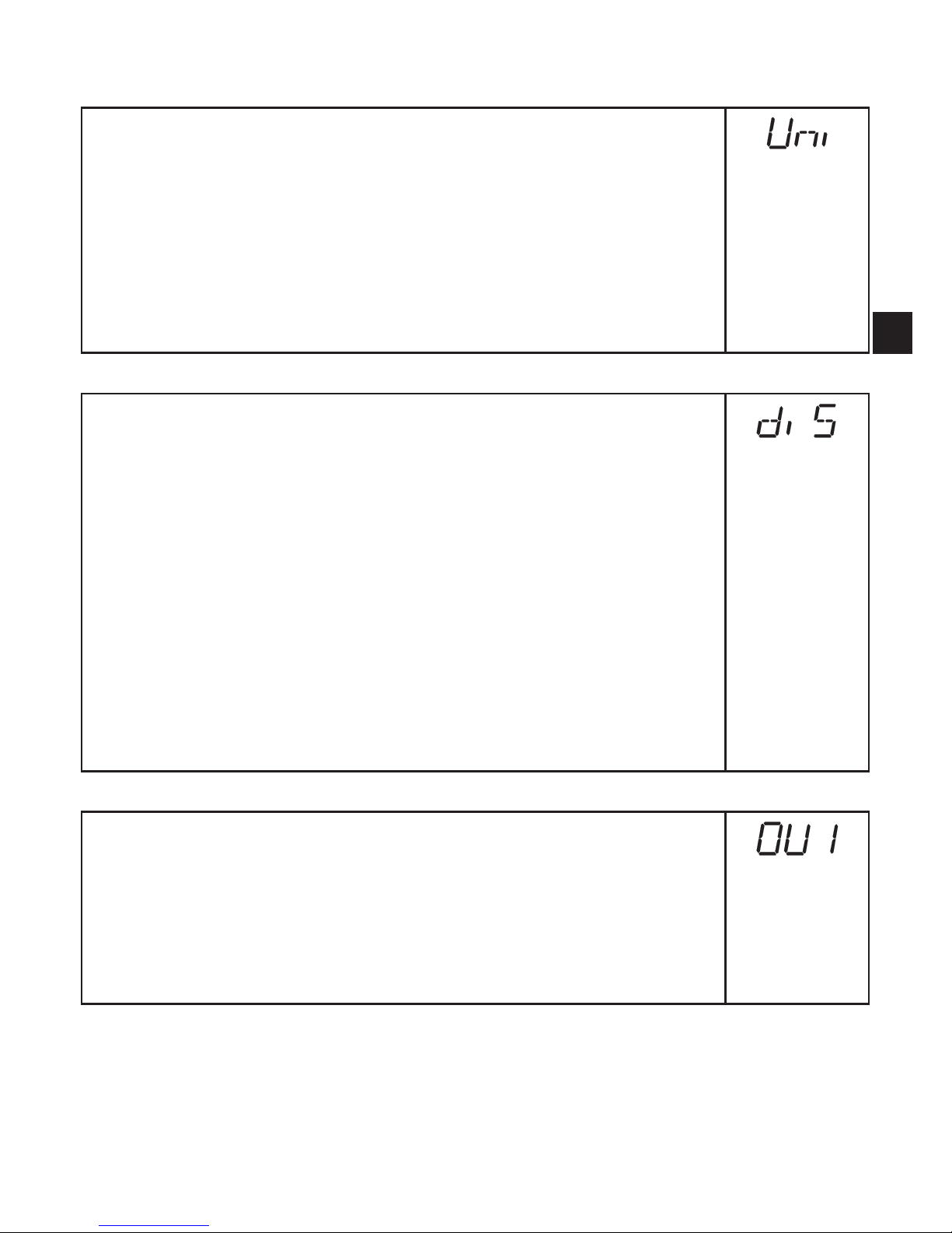
9.2.1 Selection of the display unit
Set [Uni] before the values for the parameters [SPx], [nSPx], [FSPx],
[ASP], [AEP] are defined�
In case of subsequent changes of the display unit rounding errors during
internal conversion to other units may falsify the set values�
►Change to [EF]�
►Select [Uni] and set the unit of measurement�
Selection of the unit of measurement: [mm], [m], [inch]
►Confirm with [MODE/ENTER]�
> The selected unit is indicated by a green LED on the display�
9.2.2 Setting the display
►Change to [EF]�
►Select [diS] and make settings�
7 settings can be selected:
•[d1] = update of the measured values every 50 ms�
•[d2] = update of the measured values every 200 ms�
•[d3] = update of the measured values every 600 ms�
•[rd1], [rd2], [rd3] = display like [d1], [d2], [d3] but rotated by 180°�
The update of the measured value only refers to the display� It has no
effect on the outputs�
•[OFF] = the measured value display is deactivated in the Run mode�
When one button is pressed the current measured value is displayed
for 15 s�
►Confirm with [MODE/ENTER]�
The LEDs remain active even if the display is deactivated�
9.2.3 Configure OUT1
►Select [OU1] and set the switching functions�
Switching functions:
•[Hno] = hysteresis function / normally open
•[Hnc] =
hysteresis function / normally closed
•[Fno] = window function / normally open
•[Fnc] = window function / normally closed
►Confirm with [MODE/ENTER]�
16
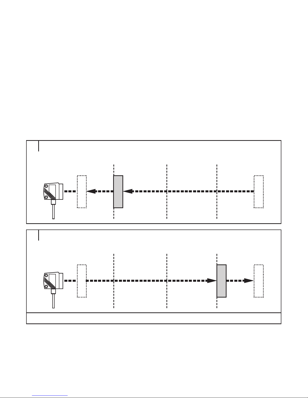
9.2.4 Hysteresis function
The hysteresis keeps the switching state of the output stable if the measured
value varies about the sensing range� In both cases the set and reset points are
symmetrically arranged about the selected switch point [SPx]� The hysteresis
is the distance between set and reset points; it is calculated on the basis of the
repeatability with a safety factor of 1�5�
Example Hno
1� For the output function [Hno] the output switches when the object approaches
and when the set point (A) is reached�
2� When the object is removed again, the output does not switch back before the
reset point (B) is exceeded�
The reset point (B) is above the set point (A)�
1
2
[SPx] =
switch point;
A = set point; B = reset point
If the output function [Hnc] has been selected, the set and reset points are
reversed� The output switches off when the object approaches� When the object is
removed again, the output switches�
17
UK
Switching state of the outputs
Output function Object distance (D) Output status
[Hno] D < [SPx] closed
D > [SPx] open
[Hnc] D < [SPx] open
D > [SPx] closed
Example of output function [Hno]
Sampling rate 15 Hz, distance to the object 1200 mm, grey value (18 % remission):
Hysteresis=±8mm(repeatability→9.3.3table)xfactor1.5=12mm
- Reset point 1200 mm + (12 mm) = 1212 mm
- Set point 1200 mm - (12 mm) = 1188 mm
9.2.5 Setting of the switch point for hysteresis function OUT1
►In [OU1] select the output function [Hno] or [Hnc]�
►Confirm with [MODE/ENTER]�
►Select [SP1] and set the switch point�
►Confirm with [MODE/ENTER]�
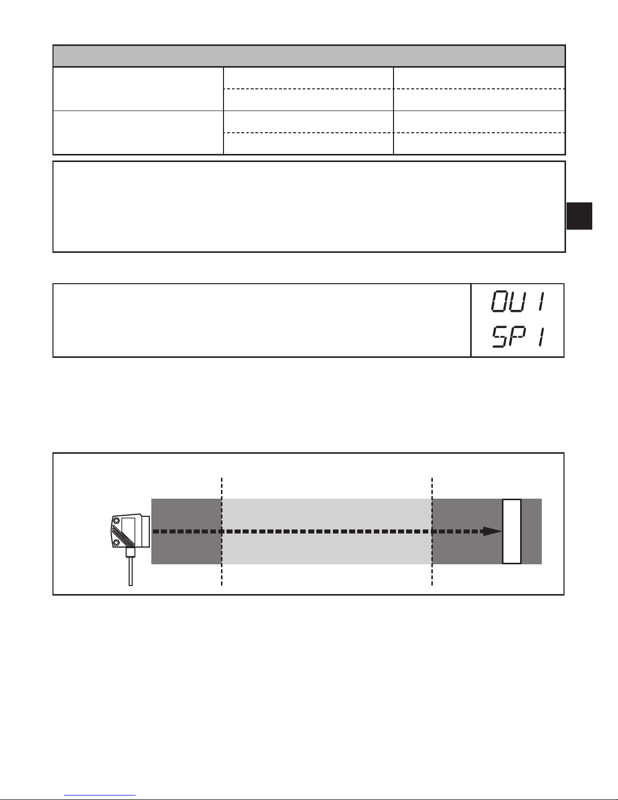
9.2.6 Window function
It is possible to define a window for the object recognition for each of the two
outputs (OUT1 / OUT2)�
Switches when the object is detected
[nSPx] =
switch point
"
near
"; [FSPx] =
switch point
"
far
"; FE = window
If the measured value is between the switch point "near" [nSPx] and the switch
point "far" [FSPx], the output is closed (when [OUx] = [Fno])�

18
Switches off when the object is detected
[nSPx] =
switch point
"
near
"; [FSPx] =
switch point
"
far
"; FE = window
If the measured value is between the switch point "near" [nSPx] and the switch
point "far" [FSPx], the output is open (when [OUx] = [Fnc])�
Switching state of the outputs
Output function Object distance (D) Output status
[Fno]
D < [nSPx] open
D > [FSPx]
[nSPx] < D < [FSPx] closed
[Fnc]
D < [nSPx] closed
D > [FSPx]
[nSPx] < D < [FSPx] open
Both window limit values ([nSPx] and [FSPx]) work with a switching hysteresis
→9.2.4Hysteresisfunction/exampleforoutputfunction[Hno].
9.2.7 Setting of the switch points for window function OUT1
►In [OU1] select the output function [Fno] or [Fnc]�
►Confirm with [MODE/ENTER]�
►Select [nSP1] and set the switch point "near"�
►Confirm with [MODE/ENTER]�
►Select [FSP1] and set the switch point "far"�
►Confirm with [MODE/ENTER]�

19
UK
9.2.8 Configure OUT2
►Select [OU2]�
►Set switching functions or analogue signals:
•[Hno] = hysteresis function / normally open
•[Hnc] = hysteresis function / normally closed
•[Fno] = window function / normally open
•[Fnc] = window function / normally closed
•[I] = current output analogue 4���20 mA
•[U] = voltage output analogue 0���10 V
►Confirm with [MODE/ENTER]�
9.2.9 Setting of the switch point for hysteresis function OUT2
►In [OU2] select [Hno] or [Hnc]�
►Confirm with [MODE/ENTER]�
►Select [SP2] and set the switch point�
►Confirm with [MODE/ENTER]�
→9.2.4Hysteresisfunction
9.2.10 Setting of the switch points for window function OUT2
►In [OU2] select [Fno] or [Fnc]�
►Confirm with [MODE/ENTER]�
►Select [nSP2] and set the switch point "near"�
►Confirm with [MODE/ENTER]�
►Select [FSP2] and set the switch point "far"�
►Confirm with [MODE/ENTER]�
→9.2.6Windowfunction
9.2.11 Scaling of the measuring range (analogue output)
►In [OU2] select [I] or [U]�
►Confirm with [MODE/ENTER]�
►Select [ASP] and set the "Analogue start point"�
With [ASP] you define at which measured value the output signal is
4 mA / 0 V�
►Confirm with [MODE/ENTER]�
►Select [AEP] and set the "Analogue end point"�
With [AEP] you define at which measured value the output signal is
20 mA / 10 V� It can also be selected so that it is before [ASP]� This
implements a falling edge�
►Confirm with [MODE/ENTER]�
Minimum distance between [ASP] and [AEP]: 100 mm
When the minimum distance is not reached, the error message "SIZE" is
displayed�

20
Current output 4 ... 20 mA
Factory setting Measuring range scaled
MEW = final value of the measuring range
In the set measuring range the output signal is between 4 and 20 mA�
Faults are also displayed:
Too much light or object too near: 3�5 mA for a rising edge ([ASP] < [AEP]), 20�5 mA for
falling edge ([ASP] > [AEP])�
Object too far or no object present:
20�5 mA for rising edge; 3�5 mA for falling edge�
Voltage output 0 ... 10 V
Factory setting Measuring range scaled
MEW = final value of the measuring range
In the set measuring range the output signal is between 0 and 10 V�
Table of contents
Popular Accessories manuals by other brands

Elektrotechnik Schabus
Elektrotechnik Schabus GX-SE operating instructions

RADEMACHER
RADEMACHER DuoFern Operating and assembly manual

BaiYou Electronic
BaiYou Electronic BY213-C021-W installation instructions

Sharpal
Sharpal 104N user manual

Banner
Banner QS30LLPQ manual

Festo
Festo VN Series Assembly instructions


ROSE DISPLAYS
ROSE DISPLAYS ANOSKYBOX-TOP LOADING 3 WAY manual

Daikin
Daikin EKRSCA1 installation manual

Airdream
Airdream Vision DL 300 User instruction

texet
texet PowerPack Series manual

National Instruments
National Instruments Portable Monitor Accessory NI PMA-1115 user guide

SICK
SICK KTS Prime instructions