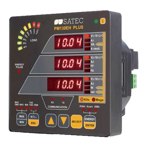
Automess 6150AD1 User manual

Operating Manual
for the
Dose Rate Meter
6150AD
referring to
these models
:
6150AD1
to
6150AD6,
6150AD1/H
to
6150AD6/H
,
6150AD1/E
to
6150AD6/E
.
Daimlerstrasse 27
Telefon
+49(0)6203-9503-00
http://www.automess.de
USt.-ID-Nr. / VAT ID No.
D-68526 Ladenburg
Telefax
+49(0)6203-9503-29
eMail: [email protected]
DE 144 458 420
Automation und Messtechnik GmbH
24 March 2004
Dose Rate Meter
6150AD

1. Application
............................................................................
1
...
2. 6150AD Models
.......................................................................
1
...
3. Construction
..........................................................................
6
...
3.1 Housing
..........................................................................
6
...
3.2 Location of Detector
..............................................................
6
...
3.3 Display
...........................................................................
6
...
3.4 Speaker
..........................................................................
7
...
3.5 Keys
.............................................................................
7
...
3.6 Probe Socket
.....................................................................
7
...
4. Functions
..............................................................................
8
...
4.1 Dose Rate Measurement
..........................................................
8
...
4.2 Audible Single Pulse Detection
...................................................
8
...
4.3 Dose Rate Alarm
.................................................................
8
...
4.4 Dose Rate Mean Value
...........................................................
9
...
4.5 Dose Rate Maximum Value
......................................................
10
.
4.6 Dose
.............................................................................
10
.
4.7 Non-volatile Dose Memory (6150AD3/4/5/6 only)
................................
11
.
4.8 Dose Alarm (6150AD3/4/5/6 only)
...............................................
12
.
4.9 Checking the Battery
.............................................................
13
.
4.10 Calibration
......................................................................
13
.
4.11 Operation with Probes
...........................................................
13
.
5. Operation
.............................................................................
14
.
5.1 Probe Connector Locking
.........................................................
14
.
5.2 Replacing the Battery
.............................................................
14
.
5.3 Automatic Battery Warning
.......................................................
14
.
5.4 Switching On and Off, Erase Function of the On/off Key
..........................
15
.
5.5 Illumination Key
.................................................................
16
.
5.6 Signal Key (Loudspeaker Key)
...................................................
16
.
5.7 Functions called by the Function Key (Arrow Key)
................................
16
.
5.7.1 Indication of Dose Rate
.....................................................
17
.
5.7.2 Indication of Dose Rate Mean Value
........................................
18
.
5.7.3 Indication and Selection of Dose Rate Alarm Threshold
.....................
18
.
5.7.4 Indication of Dose Rate Maximum Value
...................................
19
.
5.7.5 Indication of Dose
..........................................................
19
.
5.7.6 Indication and Selection of Dose Alarm Threshold (6150AD3/4/5/6 only)
...
20
.
5.7.7 Indication of Battery Voltage
................................................
20
.
5.7.8 Indication of Calibration Parameters
........................................
21
.
Contents I
Daimlerstrasse 27
Telefon
+49(0)6203-9503-00
http://www.automess.de
USt.-ID-Nr. / VAT ID No.
D-68526 Ladenburg
Telefax
+49(0)6203-9503-29
eMail: [email protected]
DE 144 458 420

6. Display Ranges and Display Formats
..................................................
22
.
6.1 Dose Rate
........................................................................
22
.
6.2 Dose Rate Mean Value
...........................................................
24
.
6.3 Dose Rate Alarm Threshold
......................................................
25
.
6.4 Dose Rate Maximum Value
......................................................
25
.
6.5 Dose
.............................................................................
26
.
6.6 Dose Alarm Threshold (6150AD3/4/5/6 only)
.....................................
26
.
7. Measuring Ranges
.....................................................................
27
.
7.1 Dose Rate Measuring Ranges
.....................................................
27
.
7.2 Dose Measuring Ranges
..........................................................
28
.
8. Fixed Alarm Thresholds
...............................................................
28
.
8.1 Dose Rate Alarm Thresholds
.....................................................
29
.
8.2 Dose Alarm Thresholds (6150AD3/4/5/6 only)
....................................
29
.
9. Energy Dependence and Directional Dependence
......................................
30
.
9.1 6150AD1, 6150AD3, 6150AD5
..................................................
31
.
9.2 6150AD1, 6150AD3, 6150AD5 (/H and /E models)
...............................
32
.
9.3 6150AD2, 6150AD4, 6150AD6
..................................................
33
.
9.4 6150AD2, 6150AD4, 6150AD6 (/H and /E models)
...............................
34
.
10. Time Constant and Standard Deviation
...............................................
35
.
11. Radiological Check
..................................................................
36
.
12. Programming the 6150AD3/4/5/6
....................................................
38
.
12.1 Individual Dose Rate Alarm Threshold
..........................................
39
.
12.2 Individual Dose Alarm Threshold
...............................................
40
.
12.3 Post-alarm Increment for Dose Alarm
...........................................
40
.
12.4 Enabling or Disabling non-volatile Dose Storage
................................
41
.
12.5 Resetting to Factory Setting
.....................................................
41
.
13. Wall Holders (Accessories)
...........................................................
42
.
14. Technical Data
.......................................................................
43
.
14.1 6150AD
.........................................................................
43
.
14.2 Source Holder 761.1
............................................................
45
.
14.3 Wall Holder 761.8
..............................................................
45
.
14.4 Wall Holder with AC Adapter 761.13
...........................................
46
.
14.5 Serial Interface of the 6150AD
..................................................
46
.
Appendix: 6150AD3/4/5/6 Programming Flow Chart
.....................................
48
.
Contents II
Daimlerstrasse 27
Telefon
+49(0)6203-9503-00
http://www.automess.de
USt.-ID-Nr. / VAT ID No.
D-68526 Ladenburg
Telefax
+49(0)6203-9503-29
eMail: [email protected]
DE 144 458 420

Daimlerstrasse 27
Telefon
+49(0)6203-9503-00
http://www.automess.de
USt.-ID-Nr. / VAT ID No.
D-68526 Ladenburg
Telefax
+49(0)6203-9503-29
eMail: [email protected]
DE 144 458 420

1
.
Application
The 6150AD is a portable, battery operated dose rate meter to measure photon radiation (gamma and X
radiation). A built-in GM counting tube serves as the detector..
NOTE!
The internal counting tube is operated from a 500 V high voltage! Touching that high
voltage may be hazardous to your health, so never try to open or repair the instrument!
The 6150AD comes in various models that differ by the type of built-in GM tube and by the scope of
functions. Section 2 summarizes the various models.
As implied by the letters »AD« in its name, the 6150AD displays dose rate in both analog and digital
form. Furthermore, it permanently measures dose rate mean value, dose rate maximum value, and
accumulated dose. You may look at any of those values at any time just by pressing a key. At low levels,
the dose rate mean value permits much more accurate readings than the normal dose rate indication with
its statistical fluctuations would allow. This is particularly useful when measuring low contamination
values with external probes.
All models have alarm thresholds for dose rate, some models also for dose. Some models have
programmable thresholds that allow you to set alarm thresholds to any value within the instrument’s
range. All models support audible single pulse detection.
Particular advantages of the 6150AD are its robust and waterproof construction, and its simple operation.
Automatic range selection and clear LCD indications help to avoid operational errors.
The 6150AD supports various probes for various applications: measurement of low or high dose rate
photon radiation, detection of alpha and beta radiation, measurement of contamination of solids or
liquids. Therefore, the 6150AD - with an external probe if necessary - is well suited for many radiation
protection measuring tasks.
This manual shall not discuss the radiological features of the probes; there are separate manuals for the
probes. This manual only describes those probe features that are determined by the 6150AD and not by
the probe itself. Among the features determined by the 6150AD are, for example, ranges and alarm
thresholds of the probes.
One pin of the probe connector is a serial interface that allows to read and process dose rate by a
computer.
2
.
6150AD Models
The various models reflect the instrument’s history. Serial production started in 1986 with models
6150AD1 and 6150AD2. These two models differ by the type of built-in counting tube and therefore by
range. The 6150AD1 has a smaller, that is less sensitive tube (type ZP1310) covering dose rates up to
1 Sv/h. The 6150AD2 has a larger tube (type ZP1200) which only covers dose rates up to 10 mSv/h, but
which is better suited for low levels because of its higher sensitivity. The more favourable model depends
on the application. If dose rates above 10 mSv/h are unlikely to occur, the 6150AD2 is preferred,
otherwise the 6150AD1. As far as operation and function are concerned, both models are completely
equal.
03/2004
Operating Manual 6150AD
Page
1
Daimlerstrasse 27
Telefon
+49(0)6203-9503-00
http://www.automess.de
USt.-ID-Nr. / VAT ID No.
D-68526 Ladenburg
Telefax
+49(0)6203-9503-29
eMail: [email protected]
DE 144 458 420

During years of experience with the models 6150AD1/2 some users requested additional functions such
as:
Protection against unintentional switching off,
Non-volatile storage of the dose measured with the internal tube,
Dose alarm,
Programmable alarm thresholds for dose and dose rate,
Better resolution (more places after the decimal point) when indicating dose, alarm threshold, and so
on.
We met these requirements by introducing a new hardware release and extending the microprocessor’s
program. However, additional functions will inevitably make operating the instrument a little more
complex. Users who do not need the additional functions may prefer a simple model. For those users we
decided to continue the models 6150AD1/2, and to create »more intelligent« successors called 6150AD3
and 6150AD4. The 6150AD3/4 models are in the market since 1990. The 6150AD3 has the same
hardware and the same GM tube as the 6150AD1, which means it is the more intelligent successor of the
6150AD1. Internally the only difference between a 6150AD3 and a 6150AD1 is the contents of its
program memory (EPROM). In the same sense the 6150AD4 is the successor of the 6150AD2.
In 1994 the Scintillator Probe 6150AD-b came on the market. This probe required another modification
of the 6150AD for the following reason: as mentioned earlier, the 6150AD will automatically select
ranges and units when connecting an external probe. For this purpose the 6150AD needs certain
information about each probe type. The previous models 6150AD1-4 do not know the new probe type;
they indicate »Err ext« when connecting a 6150AD-b probe or some other unknown probe type.
Therefore we created the models 6150AD5 and 6150AD6, which will also identify the 6150AD-b probe.
We also used this occasion to add as a new function the indication of the relative standard deviation of
dose rate mean value. Again, the 6150AD5/6 models differ from their predecessors 6150AD3/4 only by
contents of the program memory.
Introducing the models 6150AD5/6 made the models 6150AD3/4 more or less unnecessary. Their
function is almost equal, and the additional ability of the 6150AD5/6 to identify the probe 6150AD-b is
surely no drawback. When buying a new instrument (without the need to recognize the 6150AD-b probe),
the only reason to prefer the 6150AD3/4 to the 6150AD5/6 would be that the user already has
6150AD3/4 models and wishes to keep his variety of models as small as possible. For this purpose the
6150AD3/4 is still available.
Next we have to discuss measuring quantity and unit. The 6150AD1/2 models are available in
R(Roentgen) units (measuring quantity is Exposure Dose J
S
) and in Sv(Sievert) units (measuring quantity
is Photon Dose Equivalent H
X
). Note that J
S
can be converted to H
X
according to
H
X
[Sv] = 0.01 Sv/R
J
S
[R]
independent of photon energy. This means that J
S
and H
X
are very close related quantities, they just differ
by a factor of 100. Because this conversion is independent of energy, the 6150AD3/4/5/6 models allow
the user to select one of the two units R and Sv. H
X
is the legal quantity in Germany since 1986; however,
the quantity H
X
was hardly accepted internationally.
Page
2
Operating Manual 6150AD
03/2004
Daimlerstrasse 27
Telefon
+49(0)6203-9503-00
http://www.automess.de
USt.-ID-Nr. / VAT ID No.
D-68526 Ladenburg
Telefax
+49(0)6203-9503-29
eMail: [email protected]
DE 144 458 420

In 2000, we created models for Ambient Dose Equivalent H*(10), which is also measured in Sv. This
required modification of energy dependence, which means modification of energy compensation. The
energy compensation is an alloy of heavy metals surrounding the counting tube. When replacing the
energy compensation and re-calibrating any 6150AD1-6, the instrument will be suited for H*(10). All
functions remain unchanged, even modifying the software (EPROM) is not absolutely necessary.
However, software (EPROM) should also be adapted, since H*(10) models must no longer allow to
switch the unit from Sv to R because this conversion is energy dependent.
If you feel confused that models for different quantities (H
X
models and H*(10) models) use the same
unit (Sv), keep in mind that a measuring
quantity
and its
unit
are different things. For example, think of
an alternating current: it may be characterized by different quantities like peak value or root-mean-square
value, which will have different values, although they are measured with the same unit (volts, amps). The
same is true for a radiation field: you may measure its quantity as H
X
or as H*(10), and you will get
different results, although both are measured in Sv.
The same is true for the probes, which means H*(10) probes also need modification of their energy
compensation. The question arises, what will happen, if 6150AD and probe are designed for different
measuring quantities. This is no real problem, because each device will measure its quantity. When
measuring with an external probe, the probe’s technical data including measuring quantity apply. A probe
designed for H
X
will always provide H
X
measurements, even if the indicating 6150AD is already designed
for H*(10). The other way round, a probe designed for H*(10) will always provide H*(10)
measurements, even if the indicating 6150AD is still designed for H
X
. Therefore it is possible to work
with a »mixture« of dose rate meters 6150AD and probes that are not designed for the same measuring
quantity. However, you have to be careful to add the measuring quantity when documenting your
readings.
An alternative would be to design the H*(10) models of 6150AD and probes in such a way that they will
not work together with the old H
X
models. The advantage of this approach is that you have to take less
care of the measuring quantity when working with an external probe; 6150AD H
X
models will only work
with H
X
probes, and 6150AD H*(10) models will only work with H*(10) probes. However, there is also a
disadvantage: if you already have several 6150AD and probe models for H
X
, and you want to upgrade
them to H*(10) models, you have to do that for all instruments at the same time, because otherwise the
probes would not work together with the 6150ADs.
We decided to offer both possibilities. This means that two H*(10) versions are available for each
6150AD model and for each probe model. Those H*(10) versions that will also work with old H
X
models
get the suffix »/H« to their old type name, those H*(10) versions that will only work with new H*(10)
models get the suffix »/E« to their old type name.
When upgrading a 6150AD to a »/H« model, energy compensation and type label have to be replaced.
This is possible even for the oldest instruments. The program version (EPROM) has only to be modified
if the instrument’s unit was other than Sv, or if the instrument allowed adjusting the unit to something
other than Sv. When upgrading to a »/E« model, the program version (EPROM) has always to be
modified. This is only possible from hardware release 2 on. In other words, upgrading to a »/E« model is
not
possible for instruments with hardware release 1. The serial number tells you which hardware release
an instrument carries, see the table at the bottom of the next page.
Both »/H« and »/E« models clearly indicate the measuring quantity H*(10) on their type label. If there is
no such indication, and if the suffixes »/H« and »/E« are missing, the instrument is an old one designed
for H
X
.
03/2004
Operating Manual 6150AD
Page
3
Daimlerstrasse 27
Telefon
+49(0)6203-9503-00
http://www.automess.de
USt.-ID-Nr. / VAT ID No.
D-68526 Ladenburg
Telefax
+49(0)6203-9503-29
eMail: [email protected]
DE 144 458 420

The table below summarizes the various 6150AD models.
6150AD Models
range
up to
measuring quantity
(unit)
additional
functions
recognizes probe
6150AD-b
software version
EPROM
Flash
6150AD1
1 Sv/h
H
X
or J
S
(Sv or R)
no
no
2.02
2.04
6150AD3
yes
no
35.00
35.01
6150AD5
yes
yes, 6150AD-b (/H)
41.00
41.01
6150AD1/H
H*(10)
(Sv)
no
no
2.02
2.04
6150AD3/H
yes
no
57.00
57.02
6150AD5/H
yes
yes, 6150AD-b (/H)
52.00
52.02
6150AD1/E
no
no
2.03
2.05
6150AD3/E
yes
no
57.01
57.03
6150AD5/E
yes
6150AD-b/E only
52.01
52.03
6150AD2
10 mSv/h
H
X
or J
S
(Sv or R)
no
no
2.02
2.04
6150AD4
yes
no
35.00
35.01
6150AD6
yes
yes, 6150AD-b (/H)
41.00
41.01
6150AD2/H
H*(10)
(Sv)
no
no
2.02
2.04
6150AD4/H
yes
no
57.00
57.02
6150AD6/H
yes
yes, 6150AD-b (/H)
52.00
52.02
6150AD2/E
no
no
2.03
2.05
6150AD4/E
yes
no
57.01
57.03
6150AD6/E
yes
6150AD-b/E only
52.01
52.03
Also, the electronics (hardware) had to develop in time due to changes and progress in technology.
Hardware release 2 became necessary because of the increased functionality of models 6150AD3 and
6150AD4. When hardware release 2 could no longer be manufactured because some of the electronic
components were no longer available, it had to be replaced by hardware release 3. Until now there is a
total of three hardware releases that are summarized in the table below:
hardware
release
construction
years
models
serial numbers
remarks
1
from 1986
to 1989
6150AD1 (/H)
and
6150AD2 (/H)
only
6150AD1:
up to 64 039
6150AD2:
up to 65 601
logic ICs as SMDs (surface mounted
devices), other parts as »through hole«
types; microprocessor with EPROM
27C32 (24 pins, 4 kbytes).
2
from 1990
to 2003
all models
up to 114 924
mostly SMDs; microprocessor with
EPROM 27C64 ... 27C512 (28 pins,
8 kbytes ... 64 kbytes).
3
since 2004
all models
from 114 925 on
all parts SMDs except transformers and
calibration switches; microprocessor
with flash memory (60 kbytes).
Page
4
Operating Manual 6150AD
03/2004
Daimlerstrasse 27
Telefon
+49(0)6203-9503-00
http://www.automess.de
USt.-ID-Nr. / VAT ID No.
D-68526 Ladenburg
Telefax
+49(0)6203-9503-29
eMail: [email protected]
DE 144 458 420

Models for H
X
and J
S
(all models without »/H« or »/E« suffix) are also available as »Gray« versions. They
are not included in the table on the previous page for space reasons. Note that Gray versions use the same
calibration factor, which means they assume that 1 Gy = 100 R.
Probes are divided into two categories: the first category, henceforth called »Sv-probes«, comprises all
probes indicating dose rate units (Sv/h, R/h, Gy/h). The second category, henceforth called »pulse
probes«, comprises all probes indicating pulse rate (S
-1
).
The 6150AD recognizes the following Sv-probes, which are also available as »/H« and »/E« versions just
like the 6150AD itself:
-
Gamma Probe 6150AD-15 (/H, /E),
-
Gamma Probe 6150AD-18 (/H, /E),
-
Telescopic Probe 6150AD-t (/H, /E),
-
Scintillator Probe 6150AD-b (/H, /E) (only with 6150AD5/6 as a meter).
The 6150AD recognizes the following pulse probes:
-
Alpha-Beta-Gamma Probe 6150AD-17,
-
Liquid Probe 6150AD-19,
-
general pulse rate probe 6150AD-0 (for example 6150AD-k, Cerberus 763).
Pulse probes serve to detect contamination or activity, not to measure dose rate. Therefore they are not
affected by the measuring quantities J
S
, H
X
, and H*(10); they do not require »/H« or »/E« versions..
The table below summarizes compatibility between 6150AD meters and probes.
Compatibility with Probes
Probe
Meter
6150AD1 -
6150AD6
6150AD1/H -
6150AD6/H
6150AD1/E -
6150AD6/E
Sv-probes for H
X
or J
S
yes
yes
error 2
Sv-probes for H*(10) /H models
yes
yes
error 2
Sv-probes for H*(10) /E models
error 1
error 1
yes
Pulse probes
yes
yes
yes
All combinations of meter and probe marked »yes« work normally. Errors 1 and 2 display an error
message instead of indicating measuring data:
The flashing symbols »ext« and »ext xy« point out that the error is related to the external probe. Error 1
tells you that the 6150AD noticed the probe, but that it does not know the probe type (»xy« in »ext xy«
left blank). All 6150AD models will indicate this error with unknown probes. Usually unknown probes
are such probe types that were developed later that the meter like, for example, the Scintillator Probe
6150AD-b that is unknown to all 6150AD1-4 models. But also hardware errors may lead to this message:
if the 6150AD cannot read the probe type because of some electronic fault in the probe, the probe will
appear unknown to the meter.
ext
ext
xy
error 1:
error 2:
15
xy =
18
t
b
03/2004
Operating Manual 6150AD
Page
5
Daimlerstrasse 27
Telefon
+49(0)6203-9503-00
http://www.automess.de
USt.-ID-Nr. / VAT ID No.
D-68526 Ladenburg
Telefax
+49(0)6203-9503-29
eMail: [email protected]
DE 144 458 420

With error 2 the 6150AD tells you that it correctly identified the probe (»xy« in »ext xy« set accordingly),
but that it refuses to indicate measuring data because the probe may not be designed for H*(10). Only
6150AD »/E« models will issue this error message to ensure that they will operate with »/E« probes only.
Operation and function do not depend on the measuring quantity. Therefore, from now on we shall
mention the »/H« and »/E« suffixes only if they are significant, for example when discussing energy
dependence and directional dependence. Unless stated otherwise, all specifications for a model 6150ADx
also apply to the corresponding H*(10) models 6150ADx/H and 6150ADx/E.
Likewise, we shall not further discuss the J
S
(Roentgen) versions, because this unit is »out of fashion«.
All »R« versions have exactly the same ranges as their H
X
(Sv) counterparts; they just convert all
indications according to the factor 100 R/Sv.
3
.
Construction
3
.
1
Housing
The housing is made of waterproof aluminium die casting and has a dark grey scratch-resistant coating.
The reverse side carries a short form instruction label and the battery compartment cover, which is fitted
with two twist locks. The battery compartment is separated from the electronics compartment by a
watertight dividing wall to prevent moisture or other impurities from entering the interior of the
instrument when the battery is replaced.
Two eyelets at the bottom corners of the instrument allow fastening the carrying strap.
The housing design meets degree of protection IP 67 according to DIN 40050 (protection against
penetration of dust and protection on immersion in water); the instrument is thus easy to decontaminate.
3
.
2
Location of Detector
The counting tube is located in the centre of the front directly behind the housing wall. A marking spot on
the front side indicates this location; it also serves to place a check source. The preferential direction (the
direction of radiation incidence with best measuring accuracy) is perpendicular on that marking spot. The
triangular arrow symbol on the top side above the LCD also indicates this preferential direction.
3
.
3
Display
The display is a static (non-multiplexed) custom designed liquid crystal display (LCD) with an
electroluminiscence lamp as a backlight.
µSv/h
perpendicular onto marking spot
on front side
centre of counting tube:
12 mm behind the front wall
preferential direction:
Page
6
Operating Manual 6150AD
03/2004
Daimlerstrasse 27
Telefon
+49(0)6203-9503-00
http://www.automess.de
USt.-ID-Nr. / VAT ID No.
D-68526 Ladenburg
Telefax
+49(0)6203-9503-29
eMail: [email protected]
DE 144 458 420

3
.
4
Speaker
A piezo buzzer emits audible signals using the housing area among the four keys as a diaphragm, so that
no hole is required for a loudspeaker.
3
.
5
Keys
The top side carries four keys made of silicone rubber, which provide a clear tactile feel, and which can
be easily operated even with heavy working gloves. The keys are:
1
.
On/off key, symbol
2
.
Function key (arrow key) to select various functions, symbol
3
.
Illumination key, symbol
4
.
Signal key for audible signals and selecting alarm thresholds, symbol
3
.
6
Probe Socket
A socket on the left-hand side of the instrument serves to connect external probes. The probe connector is
equipped with a locking, which has to be observed when plugging or unplugging the connector, see
section 5.1.
03/2004
Operating Manual 6150AD
Page
7
Daimlerstrasse 27
Telefon
+49(0)6203-9503-00
http://www.automess.de
USt.-ID-Nr. / VAT ID No.
D-68526 Ladenburg
Telefax
+49(0)6203-9503-29
eMail: [email protected]
DE 144 458 420

4
.
Functions
4
.
1
Dose Rate Measurement
Dose rate indication is provided in digital and analog form simultaneously. The analog scale covers two
decades and consists of 32 bar graph segments arranged in the shape of an arc. Two adjacent ranges
always overlap by one decade. To make operation as easy as possible, the 6150AD automatically
switches ranges including the analog scale, the decimal point, and the unit. A short sound calls the user’s
attention every time the range was switched.
The main display is the digital display. The analog display serves merely to indicate trends because the 32
bars over two decades do not allow very accurate readings.
The 6150AD calculates and displays dose rate at one-second intervals. The one-second cycle was chosen
for ergonomic reasons. Faster changes of the display, particularly of the digital display, would be difficult
to read and would strain the user’s eye. You have to consider the one-second cycle when trying to look
for changes in dose rate. The instrument will not notice a radiation source if you move it rapidly past that
source. You have to concede the instrument at least several cycles, that is several seconds, to notice the
source. The time required to indicate the new dose rate value depends on the amount of change in dose
rate referred to its initial value. The microprocessor will assist you by adjusting response time in the best
way according to the rules of statistics. Section 10 contains more information on response time.
4
.
2
Audible Single Pulse Detection
Audible single pulse detection enables you to »hear« the pulses. This can be particularly helpful to detect
changes in dose rate. Therefore audible single pulse detection is enabled after switching the instrument
on. It may be disabled by pressing the signal key. If the loudspeaker symbol in the upper right corner of
the LCD is visible, audible single pulse detection is enabled.
Note that the piezo buzzer cannot emit more than approx. 15 clicks per second, whereas at high dose
rates much more than 15 pulses per second occur. This means that the frequency of the clicks only
reflects a small lower portion of the dose rate range. Therefore, do not try to estimate dose rate from the
click frequency; the clicks just provide an acoustic aid at low dose rates.
4
.
3
Dose Rate Alarm
As soon as dose rate reaches or exceeds the dose rate alarm threshold, the instrument issues dose rate
alarm in both audible and visible form. The alarm tone is an intermittent one (two sounds per second),
and the flashing loudspeaker symbol in the LCD takes the visual part (with /E models, the analog scale
divisions additionally flash to make the alarm even more visible). Pressing the signal key will put the
alarm tone out, whereas the symbols will continue to flash. As soon as dose rate drops below the
threshold, audible and visible warnings disappear automatically.
The 6150AD will issue dose rate alarm only in the »dose rate indication« state. You have to set the
6150AD1/2 to that state to realize a dose rate alarm. The 6150AD3/4/5/6, however, automatically
switches to the »dose rate indication« state as soon as a new dose rate alarm occurs. Therefore the
6150AD3/4/5/6 prevents a dose rate alarm from being overlooked, even if at the time of its occurrence
the instrument was in some other state.
All 6150AD models have several fixed dose rate alarm thresholds one of which the user can select. The
6150AD3/4/5/6 additionally provides a user programmable threshold, see section 12.1.
Page
8
Operating Manual 6150AD
03/2004
Daimlerstrasse 27
Telefon
+49(0)6203-9503-00
http://www.automess.de
USt.-ID-Nr. / VAT ID No.
D-68526 Ladenburg
Telefax
+49(0)6203-9503-29
eMail: [email protected]
DE 144 458 420

The dose alarm (only provided by 6150AD3/4/5/6) takes precedence over the dose rate alarm in case both
alarms should occur simultaneously.
4
.
4
Dose Rate Mean Value
The 6150AD permanently measures dose rate mean value, which can be displayed with the help of the
function key. The dose rate mean value is particularly useful at low dose rates, where direct dose rate
indication is subject to strong statistical fluctuations. The mean value provides, though at the expense of
measuring time, a statistical accuracy otherwise only achievable with much more sensitive and thus more
expensive instruments.
When reading the dose rate mean value two things must be observed:
The mean value is only reasonable if conditions were stable during its measurement. For example, if
a radiation field is to be measured more accurately with the help of the mean value, this radiation
field has to be constant in time, and the instrument has to remain at the same place during that
measurement. If these conditions are not met, the mean value will only represent a not very
meaningful average in time and space.
You must not overestimate the absolute accuracy of the mean value. It is true that by measuring long
enough you can bring down the statistical error to almost any small value, but this does not eliminate
other possible error sources such as calibration error, ambient temperature, energy and direction of
radiation, instrumental background, and so on. For example, if you leave a 6150AD2/4/6 to itself for
24 hours at natural background of approx. 70 nSv/h, the statistical error of the dose rate mean value
will be as low as 1 nSv/h. However, this does not mean you have measured natural background with
that accuracy. One uncertainty is, for example, the instrumental background. Although mostly
compensated, the instrumental background slightly varies from one instrument to the other; the
background remaining after compensation may amount up to approx. 10 nSv/h.
The main purpose of the dose rate mean value is to reduce the statistical error at constant measuring
conditions. A typical example is checking the instrument with a check source. This requires an accurate
reading and then comparing that reading with some reference value obtained earlier. What then matters is
the comparison of two values, not so much their absolute value. The dose rate mean value is best suited
for that purpose. Another example is measuring contamination with an external probe. Reading the mean
value without and with the object to be checked will allow to detect small increases in pulse rate (for
example from 0.1 to 0.3 pulses per second), which would be impossible or at least very inaccurate when
reading the pulse rate directly.
As measuring time increases, the mean value becomes increasingly accurate. As a rough indication for
accuracy, the digital display flashes until the statistical error has gone down to 5% (to be more precise:
until a relative standard deviation of 5% has been achieved). The various models use slightly different
methods to check for that 5% error limit. The 6150AD1/2/3/4 assumes the error not to exceed 5% as soon
as calculation of the mean value is based on at least 400 pulses. This is correct for statistically distributed
pulses originating from counting tubes. The 6150AD5/6, however, also has to process the pulses coming
from the Scintillator Probe 6150AD-b, which are not statistically distributed. Therefore, the 6150AD5/6
uses fluctuations of dose rate instead of total pulse count to calculate the standard deviation of the mean
value. Now, if conditions change, that is if dose rate changes, the standard deviation calculated from dose
rate fluctuations will suddenly start to increase, after it had been decreasing continuously. Consequently,
with the 6150AD5/6 you may notice the mean value to start flashing again after it had already been static.
Such behaviour indicates changing conditions. The 6150AD1/2/3/4 will not recognize such changing
conditions, because it only observes total pulse count. However, under constant conditions, both methods
are equivalent, and only constant conditions will give meaningful readings anyway. Therefore, the
03/2004
Operating Manual 6150AD
Page
9
Daimlerstrasse 27
Telefon
+49(0)6203-9503-00
http://www.automess.de
USt.-ID-Nr. / VAT ID No.
D-68526 Ladenburg
Telefax
+49(0)6203-9503-29
eMail: [email protected]
DE 144 458 420

6150AD5/6 just has the additional function that it will indicate changing conditions by an increase of
standard deviation.
Note that the time required until the 5% error limit has been achieved, and thus the flashing stops,
depends on dose rate and the sensitivity of the detector currently in use. It may range from a few seconds
to many hours.
Calculating the mean value starts when the instrument is switched on and is not limited in time. It starts
again when a probe is connected or disconnected. The 6150AD3/4/5/6 additionally allows to clear the
mean value and thus to start its calculation again. Moreover, the 6150AD5/6 is also able to indicate the
standard deviation of the mean value.
We shall shortly explain the meaning of the relative standard deviation for users who are not very
familiar with this subject. Assume you have measured some value (say, 100) with some relative standard
deviation (say, 3%). This does not mean that the »true« value (the value you would have obtained when
measuring infinitely) will certainly be within the range 100 ± 3%, that is within the range 97 to 103. It
only means that the true value will be within that range with a certain probability. Theory of statistics
says:
within one standard deviation are:
68.27%,
within two standard deviations are:
95.45%,
within three standard deviations are:
99.73% of all values.
Applied to the 100 ± 3% example this means that the true value is within the range of 97 to 103 with a
probability of approx. 68%. In other words, there is a probability of (100-68)% = 32% that the true value
is outside that range. Taking three standard deviations (3
3% = 9%) instead of one results in a range of
100 ± 9%, that is 91 to 109. The probability that the true value is within that range is as high as 99.7%;
the probability that the true value is outside that range is as small as (100-99.7)% = 0.3%. It depends on
the application how accurate a value is required. Common practice is to specify two standard deviations
as measuring accuracy. This is sometimes called a »two sigma confidence level« or »95% confidence
interval«, saying that the true value is with a probability (confidence) of 95% within the specified error
interval of ±2
σ
(the theory of statistics uses the Greek letter
σ,
»sigma«, to denote the standard deviation).
4
.
5
Dose Rate Maximum Value
The 6150AD remembers the dose rate maximum value, which can be displayed with the help of the
function key. The maximum value can be useful after a job like, for example, measuring the spatial
distribution of a radiation field.
Determination of the maximum value starts when the instrument is switched on. It starts again when a
probe is connected or disconnected. The 6150AD3/4/5/6 additionally allows to clear the maximum value
and thus to start its determination again.
4
.
6
Dose
The 6150AD permanently accumulates dose, which can be displayed with the help of the function key.
With the 6150AD1/2, dose is always zero after the instrument has been switched on, and after a probe is
connected or disconnected. The 6150AD3/4/5/6 has a non-volatile dose memory, see next section.
Page
10
Operating Manual 6150AD
03/2004
Daimlerstrasse 27
Telefon
+49(0)6203-9503-00
http://www.automess.de
USt.-ID-Nr. / VAT ID No.
D-68526 Ladenburg
Telefax
+49(0)6203-9503-29
eMail: [email protected]
DE 144 458 420

4
.
7
Non-volatile Dose Memory (6150AD3/4/5/6 only)
The 6150AD3/4/5/6 provides a non-volatile memory for the dose measured with its internal tube
(henceforth called »internal dose«), whereas the 6150AD1/2 does not. The non-volatile memory keeps its
contents even when not powered, which means it will maintain the internal dose even while the
instrument is switched off. Data retention time is at least ten years.
The internal dose is transferred to the non-volatile memory when the instrument is switched off or when a
probe is connected.
When starting to use the internal tube, that is after switching the instrument on, or after disconnecting an
external probe, the internal dose is read from the non-volatile memory. Henceforth we shall call this dose
value »pre-dose«, because it is a dose originating from a previous use. If the pre-dose is non-zero, it will
be displayed immediately. By pressing the corresponding key you now have to decide whether you want
to clear it or keep it as an initial value for the new job. Once you left this first automatic dose indication
(no matter how, by clearing or keeping the pre-dose), clearing the dose will no longer be possible for
safety reasons.
All 6150AD models treat the »probe dose« (the dose measured with a probe) in the same way: the probe
dose is always zero when connecting the probe, it cannot be cleared during operation, and it will be lost
after disconnecting the probe.
Note: As mentioned above, the internal dose is transferred to non-volatile memory when you switch the
instrument off. If you do not switch the instrument off, but just remove the battery during operation, the
current internal dose will be lost. The memory will still contain the dose prior to the last use. This fact
may be useful in the following case: Assume that after a use the internal dose seems unreasonably high
(and the instrument has not yet been switched off), and you suspect this high value to originate from a
high pre-dose. To find out the pre-dose, do not switch off but remove the battery, insert the battery again,
and switch the instrument on. It will now indicate the pre-dose.
For applications where the non-volatile dose feature is not required, the need to clear the pre-dose every
time you switch the instrument on may be annoying. In this case the 6150AD3/4/5/6 may be programmed
in such a way that pre-dose will always be zero, just as with the 6150AD1/2 (see section 12.4).
03/2004
Operating Manual 6150AD
Page
11
Daimlerstrasse 27
Telefon
+49(0)6203-9503-00
http://www.automess.de
USt.-ID-Nr. / VAT ID No.
D-68526 Ladenburg
Telefax
+49(0)6203-9503-29
eMail: [email protected]
DE 144 458 420

4
.
8
Dose Alarm (6150AD3/4/5/6 only)
The 6150AD3/4/5/6 provides dose warning, which the 6150AD1/2 does not. As soon as dose reaches the
dose alarm threshold, the instrument automatically switches to the »dose indication« state and issues dose
alarm in both audible and visible form. The alarm tone is an intermittent one (four sounds per second,
twice as fast as with dose rate alarm), and the flashing loudspeaker symbol and the flashing bar graph
take the visual part. The only way to acknowledge the dose alarm is to leave the »dose indication« state.
You can do so using the function key, or by pressing the signal key, where the latter will automatically
return to the ground state »dose rate indication«.
Apart from several fixed dose alarm thresholds the 6150AD3/4/5/6 also provides a user programmable
threshold, see section 12.2.
As soon as dose increased by a certain amount, the instrument will repeat dose warning. We shall call this
repeated alarm a »post-alarm«. The dose increment required for a post-alarm shall be called »post-alarm
increment«; it is a certain percentage of the dose alarm threshold. A post-alarm appears exactly like the
first alarm. Every time the dose increased by one post-alarm increment, the instrument issues a new
post-alarm, thereby repeatedly reminding the user that the dose exceeds the threshold. The concept of the
post-alarm is explained in more detail in the following numerical example:
Dose alarm threshold:
250 µSv
Post-alarm increment:
2% (2% of 250 µSv = 5 µSv)
Dose alarm at:
250 / 255 / 260 / 265 / ... µSv
In the above example, the first dose alarm occurs when dose is equal to or greater than 250 µSv.
Post-alarms will occur every time dose catches up with the next value in the sequence of post-alarm
thresholds. This sequence is only limited by the dose range of the detector in use.
You can set the post-alarm increment to one of these values (see section 12.3):
2% / 5% / 10% / no post-alarm
where 2% is factory setting. The post-alarm increment applies to the internal tube and to all probes. If set
to »no post-alarm«, only one dose warning will occur when the dose reaches the alarm threshold.
The post-alarm increment will be rounded off to full micro-Sieverts if necessary. For example, 10% of
94 µSv will be rounded off to 9 µSv, and 10% of 95 µSv will be rounded off to 10 µSv. Although such
»odd« thresholds are unlikely to occur, the cannot be excluded because of the programmable threshold.
Also, the post-alarm increment can never be lower than 1 µSv or greater than 50 mSv. With thresholds
lower than 15 µSv, the minimum value of 1 µSv causes that each further µSv will trigger a post-alarm
regardless whether the post-alarm increment is set to 2% / 5% / 10%.
Should dose alarm and dose rate alarm occur simultaneously, dose alarm and dose post-alarm take
precedence over the dose rate alarm. You will not notice the dose rate alarm until you acknowledge the
dose alarm by leaving dose indication.
When using the instrument with a low dose alarm threshold in a strong radiation field, post-alarms may
repeat so frequently that it is impossible to move the instrument to some state other than dose indication.
Of course, the first choice remedy would be to leave that radiation field. But there is another possibility:
acknowledge the post-alarm by keeping the signal key depressed. As long as you keep the signal key
depressed, you will be able to move to the other states using the function key as usual.
You can also use dose thresholds with pulse probes. Everything just mentioned also applies to this
category of probes, if you replace »dose« with »pulse count« and »1 µSv« with »1 pulse«. For example,
you could use a pulse count threshold if you would like to perform a measurement until a certain pulse
count corresponding to a certain accuracy is obtained; the warning would then signal the end of the
measurement.
Page
12
Operating Manual 6150AD
03/2004
Daimlerstrasse 27
Telefon
+49(0)6203-9503-00
http://www.automess.de
USt.-ID-Nr. / VAT ID No.
D-68526 Ladenburg
Telefax
+49(0)6203-9503-29
eMail: [email protected]
DE 144 458 420

4
.
9
Checking the Battery
A 9 volt battery serves as power supply. The instrument measures battery voltage when it is switched on
and from then on at five-minute intervals. You may look at the battery voltage at any time with the help
of the function key. When battery life is coming to an end, the instrument issues battery warning in both
audible and visible form. After the first occurrence of the battery warning still approx. 70 operating hours
will remain (with an alkaline battery, without illumination).
Due to low power consumption, an alkaline battery will last for approx. 1000 operating hours (approx.
3000 hours with instruments equipped with hardware release 3). With the illumination on, battery life
considerably drops to approx. 60 hours. Although alkaline batteries are recommended, zinc carbon
batteries will also do. You may also use accumulators (rechargeable batteries). However, the voltage of
accumulators gives only poor information about their capacity, therefore battery warning will be much
less reliable.
4
.
10
Calibration
The microprocessor calculates dose rate from the tube’s pulses in a purely digital way. Calibration
parameters are not stored as analog quantities like settings of variable resistors, but as digital numbers,
making them totally insensitive to drifts in time. These features ensure high measuring accuracy, also in
the long term. Calibration is done at two dose rates, therefore the instrument has two calibration
parameters. One parameter compensates the spread of sensitivity of the tubes, the other compensates dead
time loss. The calibration parameters may be viewed for service purposes, but modifying them is only
possible by adjusting two switches after opening the instrument.
4
.
11
Operation with Probes
Connecting a probe automatically turns off the internal counting tube and puts the probe’s detector in
operation. The 6150AD automatically identifies the probe type and displays it in the upper left corner of
the LCD. It automatically selects ranges and units for that probe type, including the unit pulses per
second for the pulse probes. Just like with the pulses from the internal tube, the pulses originating from
the probe are processed in a purely digital way. The microprocessor reads the probe’s digital calibration
parameters through the probe cable. Therefore you do not have to assign a certain probe to a certain
6150AD. You may operate any probe with any 6150AD without having to fear that the probe’s indication
might depend on the 6150AD used as a meter.
There are some intentional restrictions as to which probe models work with which 6150AD models, see
the table »Compatibility with Probes« at the end of section 2.
03/2004
Operating Manual 6150AD
Page
13
Daimlerstrasse 27
Telefon
+49(0)6203-9503-00
http://www.automess.de
USt.-ID-Nr. / VAT ID No.
D-68526 Ladenburg
Telefax
+49(0)6203-9503-29
eMail: [email protected]
DE 144 458 420

5
.
Operation
Note that each of the keys requires to be pressed for at least 0.25 seconds. A hasty tap on a key may be
too short to be recognized. The reason is that the 6150D samples the keys only four times per second;
during the time in between it goes into a power saving mode to save batteries.
Pressing a key that will execute some function is acknowledged by a short sound. The illumination key is
an exception; here the illumination signals that the instrument has recognized the key.
5
.
1
Probe Connector Locking
You have to pay attention to the locking of the probe connector when connecting or disconnecting
probes. This locking prevents the connector from slipping out of the socket. Plug the connector into the
socket until it clicks into place. When unplugging the connector, always seize the connector at the area
with the grooves to release the locking.
NOTE
!
Never try to unplug the connector by seizing it at its smooth end or even at the cable!
This would not release the locking and thus damage the probe cable!
5
.
2
Replacing the Battery
To open the battery compartment, the twist locks on the battery compartment cover must be pressed in as
far as possible and then twisted approx. 45° counter-clockwise. To close the compartment, align the twist
locks according to their grooves and those on the cover, slightly press down the cover, press down the
twist locks and turn them clockwise as far as possible, and finally release them. The interlocking pin of
the twist lock then snaps into place.
The shape of the battery contacts prevents the battery from being inserted with the polarity reversed.
Moreover, the instrument has an electronic reverse polarity protection; applying a reversed polarity will
not damage the instrument
You should remove the battery when not using the instrument for a prolonged period of time..
5
.
3
Automatic Battery Warning
As soon as battery voltage drops below 5.5 volt, battery life is coming to an end, and the instrument
issues battery warning in both audible and visible form. A continuous warning tone accompanies the
battery symbol flashing in the upper right corner of the LCD. Pressing the signal key will put the warning
tone out, and the battery symbol will then be permanently on. Automatic battery warning is active
independent of the state the 6150AD is currently in.
seize here to unplug
locking
Page
14
Operating Manual 6150AD
03/2004
Daimlerstrasse 27
Telefon
+49(0)6203-9503-00
http://www.automess.de
USt.-ID-Nr. / VAT ID No.
D-68526 Ladenburg
Telefax
+49(0)6203-9503-29
eMail: [email protected]
DE 144 458 420

5
.
4
Switching On and Off, Erase Function of the On/off Key
Pressing the on/off key switches the instrument on. As long as you keep the on/off key depressed, all
LCD segments are visible and the buzzer is on. This allows checking LCD and buzzer. The LCD test
looks like that:
After releasing the on/off key the 6150AD displays its software version (firmware version, program
version) for two seconds (»/E« models only):
After that the 6150AD displays battery voltage for two seconds to give you automatically an idea about
the initial battery condition:
After that the 6150AD goes to its ground state, that is dose rate indication.
If the pre-dose is non-zero (may occur with 6150AD3/4/5/6 only), then after battery voltage indication
the instrument will first indicate the pre-dose to emphasize that there is one. You now have to decide
whether you want to clear it or keep it as an initial value for dose accumulation:
If you want to clear it, press the on/off key twice within three seconds. After the second push the
instrument will clear the dose and then automatically turn to dose rate indication.
If you want to keep it, move the instrument to dose rate indication using the function key (arrow
key). Should the pre-dose have triggered dose alarm, you may also move to dose rate indication by
pressing the signal key.
It depends on the model how to switch off. The 6150AD1/2 only requires a single push on the on/off key,
no matter which state it is currently in. The 6150AD3/4/5/6 has to be in dose rate indication state; while
in this state, press the on/off key twice within three seconds. After the second push the instrument will
switch off. This shall prevent switching off by mistake or by chance.
In addition to switching on and off, the 6150AD3/4/5/6 uses the on/off key to erase some values. Pressing
that key twice within three seconds performs the following functions:
In state »mean value indication«, the current dose rate mean value will be cleared and the calculation
of a new mean value will start. With the 6150AD1/2, the only way to restart the mean value
calculation is to switch off and on again, or to connect or disconnect a probe.
In state »maximum value indication«, the current dose rate maximum value will be cleared and the
determination of a new maximum value will start. With the 6150AD1/2, the only way to restart the
maximum value determination is to switch off and on again, or to connect or disconnect a probe.
In state »dose indication«, the dose will be reset to zero and dose accumulation starts again from
zero. However, as already mentioned above, resetting of dose is only possible for the internal
0.10
100
0.50
0.20
200
500
1000
ext
max
batt
µSv/h
-1
m
/
l
R
LCD test
p v
indication of program version (p v)
Only with »/E« models
6150AD1/E to 6150AD6/E
batt
v
indication of battery voltage in volt units
03/2004
Operating Manual 6150AD
Page
15
Daimlerstrasse 27
Telefon
+49(0)6203-9503-00
http://www.automess.de
USt.-ID-Nr. / VAT ID No.
D-68526 Ladenburg
Telefax
+49(0)6203-9503-29
eMail: [email protected]
DE 144 458 420

non-volatile pre-dose that the 6150AD3/4/5/6 displays after it has been switched on or after a probe
has been disconnected.
5
.
5
Illumination Key
Pressing the illumination key switches the LCD backlight on. After releasing that key, illumination will
remain on for 10 seconds and then go off. This avoids draining the battery in case you unintentionally
switched the illumination on and did not notice it because of bright ambient conditions.
Pressing that key while illumination is already on will extend illumination time, because the 10 seconds
of automatic illumination will start again after releasing the key. This also means that you cannot turn
illumination off; instead you have to wait until the 10 seconds are over.
5
.
6
Signal Key (Loudspeaker Key)
The signal key is assigned to alarms and audible signals. It serves to acknowledge alarms and also to
select alarm thresholds. Its function depends on the state the 6150AD is currently in. The next section
discusses these states including the local function of the signal key.
5
.
7
Functions called by the Function Key (Arrow Key)
The 6150AD provides the following functions also called the »states« the instrument can be in:
Indication of dose rate (this is the ground state after the instrument has been switched on, or after a
probe has been connected or disconnected),
Indication of dose rate mean value,
Indication and selection of dose rate alarm threshold,
Indication of dose rate maximum value,
Indication of dose,
Indication and selection of dose alarm threshold (with 6150AD3/4/5/6 only),
Indication of battery voltage,
Indication of calibration parameters (instruments equipped with hardware release 3 additionally
allow for indication of the program version by pressing the signal key).
The function key allows to call these states one after the other, where the last state (calibration
parameters) returns to the ground state (dose rate). From any state, keeping the function key depressed for
three seconds will always return to the ground state.
As already mentioned earlier, the 6150AD3/4/5/6 automatically switches to the corresponding state if an
alarm occurs: on dose rate alarm it switches to dose rate indication, and on dose alarm it switches to dose
indication. Thereby it forces the user to notice the alarm. Thereafter you may again select some other
state if required.
The 6150AD1/2 does not provide dose warning, and on dose rate alarm it will not switch to dose rate
indication. You have to put the 6150AD1/2 into the dose rate indication state manually if you want to use
dose rate warning.
Pulse probes use s
-1
as a unit (pulses per second). Everything that was mentioned and that will be
mentioned also applies to this category of probes, if you replace »dose rate« with »pulse rate« and »dose«
with »pulse count«.
Page
16
Operating Manual 6150AD
03/2004
Daimlerstrasse 27
Telefon
+49(0)6203-9503-00
http://www.automess.de
USt.-ID-Nr. / VAT ID No.
D-68526 Ladenburg
Telefax
+49(0)6203-9503-29
eMail: [email protected]
DE 144 458 420
This manual suits for next models
5
Table of contents
