Young 86004 User manual

METEOROLOGICAL INSTRUMENTS
INSTRUCTIONS
R.M. YOUNG COMPANY 2801 AERO PARK DRIVE, TRAVERSE CITY, MICHIGAN 49686, USA
TEL: (231) 946-3980 FAX: (231) 946-4772 WEB: www.youngusa.com PN: 86004-90
REV: G092117
ULTRASONIC ANEMOMETER
MODEL 86004

86004-90(G)
Contents
SECTION DESCRIPTION PAGE
1.0 SPECIFICATIONS 1
2.0 INTRODUCTION 1
3.0 BEFORE INSTALLATION 1
4.0 INSTALLATION 2
4.1 Placement 2
4.2 Mounting and Alignment 2
4.3 Wiring Connections 2
5.0 OPERATION 2
5.1 Analog Outputs 2
5.2 With YOUNG Wind Tracker Display 2
5.3 Serial Output Formats and Protocols 2
5.4 Low Power Operation 3
6.0 SETTING SERIAL OUTPUTS AND OPERATING PARAMETERS
6.1 Setup using YOUNG 86SETUP program 3
6.2 Setup using terminal program 3
6.3 Command Overview 3
6.4 Command Details 4
7.0 EXAMPLE SETTINGS 5
8.0 EMC COMPLIANCE 5
9.0 WARRANTY 5
APPENDIX
A WIRING CONNECTIONS 6
B SENSOR ORIENTATION AND DIMENSIONS 9
OPERATING INSTRUCTIONS
Model 86004 Ultrasonic Anemometer


Page 1
86004-90(G)
MODEL 86004
ULTRASONIC ANEMOMETER
2.0 INTRODUCTION
The YOUNG 86004 Ultrasonic Anemometer is a 2-axis, no-
moving-parts wind sensor with integral 60 watt heater for use in
cold climates. It is ideal for general meteorological applications
requiring accurate and reliable measurement. The sensor features
wide operating range, compact size, and easy installation.
The 86004 measures wind speed and direction based on the
transit time of ultrasonic pulses between three transducers.
Measurement results are available as calibrated analog output
signals, or serial data using RS-232 or RS-485. Continuous serial
output or polled operation may be used. Serial format options
include direct connection to YOUNG Wind Tracker displays,
marine NMEA systems, data loggers, or other compatible serial
communication devices.
Operating parameters are easily set using the 86SETUP program
provided. All 86004 parameter settings are stored internally in non-
volatile memory.
The sensor is constructed using ultraviolet-stabilized thermoplastic
for superior environmental resistance. It is easily mounted on
standard 1 inch (IPS) pipe. An orientation ring preserves mounting
position when the sensor is removed.
3.0 BEFORE INSTALLATION
The 86004 arrives fully calibrated and ready to use. Unless
otherwise specied, the sensor is congured as follows:
FACTORY DEFAULT CONFIGURATION
Analog Voltage Outputs:
- Channel VI1: Wind Speed
0-5000 mV = 0-100 m/sec
- Channel VI2: Wind Direction
0-5000mV = 0-360 Deg
If using the sensor with a datalogger or other device requiring
0-5000 mV outputs, no further action is required. Simply connect
the device as shown in Appendix A, gure A1.
Other options are described in APPENDIX A. These are
accomplished using various jumper combinations and
configuring settings using the 86SETUP program available at
www.youngusa.com.
Note: Always connect and bench test a complex system
before installation in the eld.
1.0 SPECIFICATIONS
WIND SPEED
Range: 0-70 m/s (156 mph)
Resolution: 0.01 m/s
Accuracy: 0 to 30 m/s ±2% or 0.1 m/s
30 to 70 m/s ±3%
WIND DIRECTION
Azimuth Range: 0-360 degrees
Resolution: 0.1 degree
Accuracy: ± 2 degrees
SERIAL OUTPUT (Selectable)
Interface Type: RS-232 or RS-485/422
Formats: ASCII Text (polled and continuous)
RMYT (YOUNG Wind Tracker)
NMEA
Baud Rates: 1200, 4800, 9600, 19200 and 38400
ANALOG OUTPUT (Selectable)
Polar Speed: 0-5000mV or 4-20 mA (0 to 100 m/s)
Polar Direction: 0-5000mV or 4-20 mA (0 to 360° or 0 to 540°)
Cartesian UV: 0-5000mV or 4-20 mA (-100 m/s to +100 m/s)
GENERAL
Sensor:
Output rate: 0.1-20 Hz, 1 Hz typical
Power Supply: 24 VDC, 2.5A
Protection Class: IP65
EMC Compliance: FCC Class A digital device
IEC standard 61326-1
Dimensions: 29 cm high x 11 cm wide
Weight: 0.4 kg (0.9 lb)
Shipping Weight: 1.6 kg (3.5 lb)

Page 2
86004-90(G
4.0 INSTALLATION
4.1 PLACEMENT
Proper instrument placement is important. Eddies from buildings,
trees, or other structures can inuence measurements. For most
applications, locate the sensor well above or upwind of obstructions.
As a general rule, air ow around a structure is disturbed to 2 times
the height of the structure upwind, 6 times the height downwind, and
up to 2 times the height of the structure above ground.
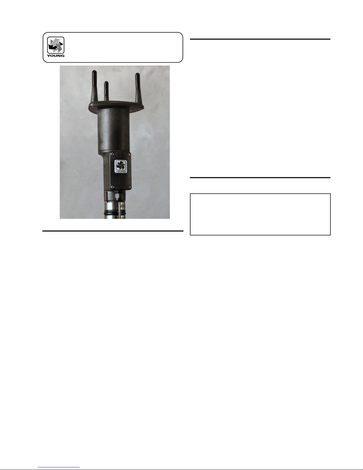
4.2 MOUNTING AND ALIGNMENT
Mount the sensor to standard 1-inch (IPS) pipe that has an outside
diameter of 1.34 inches (34 mm).
Most applications require aligning the sensor to geographic north
(0 degrees). In this orientation the sensor junction box faces
SOUTH (180 degrees). See the diagram in APPENDIX B.
4.2.1 Place orientation ring over pipe with guide pin up.
4.2.2 Place sensor mounting post over pipe.
4.2.3 Using the transducers as a sighting aid, align the
sensor with a feature on the horizon that represents
the proper orientation. After alignment, tighten the
mounting post band clamp to secure the position.
DO NOT OVER-TIGHTEN.
4.2.4 Slide the orientation ring up so its guide pin is fully
engaged in the sensor mounting post notch. Tighten the
orientation ring band clamp to secure its position.
DO NOT OVER-TIGHTEN.
If the sensor needs to be removed later, leave the orientation ring on
the pipe to preserve sensor alignment.
4.3 WIRING CONNECTIONS
Power supply voltage at the sensor +PWR and -PWR terminals must
be in the range of 22 to 26VDC to ensure proper heater operation.
When heaters are fully active, current consumption is 2.5A at 24VDC.
Use an adequately rated power supply. Limit power loss due to wire
resistance by using an adequate wire gauge and cable length. With
a 24VDC power supply and 18AWG power supply wire, cable lengths
up to 22m (75ft) could be used. Refer to WIRING DIAGRAMS in
APPENDIX A for details.
5.0 OPERATION
5.1 ANALOG OUTPUTS
As supplied, the sensor is congured for VOLTAGE OUTPUT, Wind
Speed and Wind Direction. The sensor may also be set up for 4-20
mA CURRENT output by changing internal settings. Details are in
section 6.0.
Analog VOLTAGE or 4-20mA CURRENT outputs may be
connected to a datalogger or other device such as a YOUNG 26800
Meteorological Translator. See APPENDIX A for connection details.
Analog outputs may be used simultaneously with RS-232 serial
connection. RS-485 serial output may not be used simultaneously
with analog outputs since they share connection terminals in the
junction box.
Analog outputs may be congured for either Polar (speed and
direction) or Cartesian (UV) output format.
For voltage output with cable lengths greater than 3m (10 ft.),
measure the signal differentially. Current output signals may be
measured single-ended.
5.2 USE WITH YOUNG WIND TRACKER DISPLAY
The factory default serial output format is RMYT which is compatible
with the YOUNG Model 06201 Wind Tracker display. Set the Wind
Tracker input to 'INP 09' and connect as shown in the Wiring diagram,
Fig A5, Appendix A. Note that jumpers need to be moved so the
RS-485 output is available at the connection terminals. Wind speed
and direction measurements appear on the Wind Tracker display.
See the Wind Tracker manual for display options and other details.
5.3 SERIAL OUTPUT FORMATS
Available serial output formats include RMYT, ASCII, ASCII polled,
and NMEA. The factory default format is RMYT for use with the
YOUNG Wind Tracker display. Other formats may be selected using
the 86SETUP program described in Section 6.0.
5.3.1 RMYT
RMYT is a 6-byte binary data format sent at 9600 baud using
RS -485 OUTPUT ONLY mode. This is the factory default serial format
for use with the YOUNG Model 06201 Wind Tracker.
5.3.2 ASCII
ASCII output format provides continuous wind measurement data in
text format at any of the available baud rates.
ASCII output appears either in POLAR (default) or CARTESIAN UV
format. With POLAR format, the wind speed threshold, wind speed
units, and resolution are user-selectable. With CARTESIAN the
wind threshold is ignored and wind speed units are always meters
per second (m/s).
ASCII POLAR FORMAT
a www.w ddd ss*cc<CR> Low resolution
a www.ww ddd.d ss*cc<CR> High resolution
where
a = Sensor address
www.ww = Wind speed
ddd.d = Wind direction
ss = Status code
* = Asterisk (ASCII 42)
cc = Checksum
<CR> = Carriage return (ASCII 13)
ASCII CARTESIAN (UV) FORMAT
a uu.uu vv.vv ss*cc<CR>
where
a = Sensor address
±uu.uu = U-axis wind speed (m/s)
±vv.vv = V-axis wind speed (m/s)
ss = Status code
* = Asterisk (ASCII 42)
cc = Checksum
<CR> = Carriage return (ASCII 13)
CHECKSUM is a two-character hexadecimal value (in printable
ASCII format) generated by taking the exclusive-or of all characters
up to the asterisk. STATUS CODE shows a non-zero value when
the sensor cannot acquire sufcient samples or a measurement
error has occurred.
5.3.3 ASCII POLLED
ASCII POLLED is like ASCII format described above except just
one serial output string is sent for each polling command received.
The polling command is Ma! where 'a' is the sensor address
(valid characters: 0-9, A-Z, a-z). The default address is '0'
(ASCII 48).

Page 3
86004-90(G)
5.3.4 NMEA
NMEA format provides continuous wind measurements in standard
NMEA marine sentences at 4800 baud. Use RS-485 OUTPUT ONLY
serial output mode with YOUNG Model 06206 Marine Wind Tracker
or other NMEA-capable device.
NMEA FORMAT
$WIMWV,ddd,R,www.w,N,A*cc<CR><LF>
where
ddd = Wind direction (degrees)
www.w = Wind speed (knots)
* = Asterisk (ASCII 42)
cc = Checksum
<CR><LF> = Carriage return, line feed (ASCII 13, 10)
CHECKSUM is the two-character printable hexadecimal value
generated by taking the exclusive-or of all characters between '$'
and '*'.
5.4 LOW POWER OPERATION
Average current consumption with default settings is about 20 mA.
This conguration uses minimal power and enables all features even
though they may not be used. This is suitable for many low power
applications.
To reduce current consumption further, additional strategies include
disabling unused outputs, using polled serial operation, increasing
the output interval, and limiting the sample count to the minimum
optimal number. Faster baud rates also reduce power by limiting
transmit duration.
6.0 SETTING OUTPUTS AND OPERATING
PARAMETERS
6.1 SENSOR CONFIGURATION WITH 86SETUP PROGRAM
(RECOMMENDED)
The YOUNG 86SETUP program is available from the factory web site
at www.youngusa.com. It provides an easy method for checking and
conguring sensor operation. Install the program on a Windows PC
and follow instructions that appear on the program screen to retrieve
current sensor settings or send new settings.
6.2 SENSOR CONFIGURATION USING A GENERAL-
PURPOSE COMMUNICATIONS PROGRAM
A general purpose text-based serial communications program like
HyperTerminal may be used to manually congure the sensor by
sending simple text commands.
The YOUNG sensor and communication program must operate at
the same baud rate and be properly connected. Sensor RS-232
mode must be enabled. See the RS-232 Wiring diagram, Fig A3,
in Appendix A.
Factory default sensor baud rate is 9600, but may be set to 1200,
4800, 19200 or 38400. Congure the serial communications program
for NO handshaking and 1 start, 8 data, 1 stop bit.
The sensor must be in COMMAND MODE in order to set parameters.
Enter COMMAND MODE by sending three ESC characters (ASCII
27) in quick succession while the sensor is running. When the sensor
is in COMMAND MODE, it sends a '>' prompt character indicated
that it is ready to accept commands.
If the prompt does not appear after sending three ESC characters,
re-check wiring and communication program setup. If the sensor
baud rate is unknown, try sending the ESC characters at each of
the ve available baud rates (1200, 4800, 9600, 19200 and 38400).
It is also possible that sensor parameters have been purposely
congured to disable RS-232 mode. If this the case, the following
method must be used.
In order to provide access under all conditions, the sensor always
begins operation at power up with serial communications set to 38400
baud and RS-232 connections enabled. Immediately after power up,
there is a short time window in which to send the ESC characters
and enter COMMAND MODE.
To use this feature, set your serial communication program baud rate
to 38400. Remove power then wait 5 seconds. Re-apply power to
the sensor. The sensor will transmit four asterisks immediately after
power up. After the asterisks appear, send three ESC characters.
The COMMAND MODE '>' prompt should appear.
6.3 COMMAND OVERVIEW
After the '>' prompt appears, send '??' to display a list of available
commands. Send 'RPTV' to report current settings. (Note that some
values in the report are for factory settings cannot be changed by
the user.)
Commands are case sensitive and the exact format must be used.
For example, the SET01nn command requires two digits for the serial
format code. If you send SET014 instead of SET0104 the sensor will
reject the command and indicate an error. End all commands with
a carriage return (ASCII 13). In HyperTerminal, do this by pressing
the ENTER key.
After receiving the carriage return, the sensor will evaluate the
command. Valid commands will be executed. Current settings can be
evaluated at any time by sending RPTV to get a new report.
IMPORTANT NOTE:
The YOUNG 86SETUP program automatically saves all
settings to ash memory when they are sent to the sensor.
Settings that are changed manually must be saved to ash
with the SET77 command.

Page 4
86004-90(G
6.4 COMMAND DETAILS
COMMAND DESCRIPTION
SET01nn Set OUTPUT MODE
01 Enable voltage output
03 Enable current output
04 Enable RS-232
08 Enable RS-485 output only
16 Enable RS-485 half duplex
24 Enable RS-485 full duplex
SET02n Set OUTPUT FORMAT
1 RMYT
2 ASCII
3 ASCII POLLED
4 NMEA
SET03nn Set BAUD RATE
12 1200
48 4800
96 9600
19 19200
38 38400
SET04n Set ASCII WS UNITS
1 MPH
2 KNOTS
3 KMPH
4 M/S
SET05c ASCII character sensor address (0-9, A-Z, a-z)
SET06nnn Wind speed threshold for polar output (cm/s)
SET07nnnnn Wind speed scale (nnnnn/10000)
SET08nnnnn Direction offset (±nnnnn degrees x 10)
SET09nn Damping factor
SET10nnnn Output interval (0-9999 milliseconds)
SET11nn Direction VOUT (36=0-360, 54=0-540 degrees)
SET12nnn Sample count (3 to 200)
SET13n Wind output format (0/1=Polar/UV)
SET14n Analog error code (1/2/3=None/Lo/Hi)
SET15n ASCII serial resolution(0/1=Lo/Hi)
SET16n Force analog out (0/1/2=Lo/Mid/Hi)
SET20n 86004 HTR (0/1=Enable/Disable)
SET77 SAVE SETTINGS
XX Go to OPERATE MODE
RPT Report parameter settings
?? Command Help list
6.4.1 SET01nn SET OUTPUT MODE
This enables and disables 0-5000 mV output, 4-20 mA current
output, RS-232, and RS-485. Only one of the two analog output
types (voltage or current) may be enabled at one time. Both RS-232
and RS-485 can be enabled at the same time but only one serial
output may be used.
Add together values shown in 6.4 COMMANDS SET01 to congure
multiple compatible modes. For example, to enable voltage output
and RS-232, add the code for each one: 01 + 04 = 05, SET0105. To
enable only RS-232, SET0104.
To conserve power, enable only those modes that are needed
6.4.2 SET02n OUTPUT FORMAT
This parameter determines the serial output format.
6.4.3 SET03nn BAUD RATE
Sets the baud rate for RS-232 and RS-485 serial communication.
Make sure this baud rate is the same as the connected device.
6.4.4 SET04n ASCII and NMEA WIND SPEED UNITS
Sets wind speed units for polar ASCII, ASCII POLLED, and NMEA
serial outputs.
6.4.5 SET05c POLL ADDRESS CHARACTER
Sets the sensor address for ASCII POLLED serial format. The default
is '0' (ASCII 48). This is the address recognized when the 'Ma!' polling
command is received ('a' is the address character). Valid address
characters include 0-9, A-Z, and a-z.
6.4.6 SET06nn WIND SPEED THRESHOLD
Sets the wind speed threshold for polar outputs (wind speed and
direction) to minimize erratic wind direction indications at very low
wind speeds. This allows the sensor output to mimic a mechanical
wind vane that retains its orientation when there is no wind.
Wind below the threshold is reported as zero, while the wind direction
angle is held at the last value when wind speed was above threshold.
Set threshold in centimeters per second (m/s x 100). The default
setting is 25 cm/s (0.25 m/s, 0.56 mph).
6.4.7 SET07nnnnn WIND SPEED MULTIPLIER
All wind speed measurements are multiplied by this parameter. The
default value is 10000 for a multiplier of 1.0000.
6.4.8 SET08nnnnn WIND DIRECTION OFFSET
Use this parameter to add or subtract a wind direction offset. Value
is degrees x 10 and may be positive or negative. Wind direction is
always re-scaled to a 0-360 range after offset is applied. The default
value is 00000.
6.4.9 SET09nn DAMPING FACTOR
Wind measurement outputs are damped using the following formula:
Sdamped = [(d-1) * Sdamped + Ssample] / d
where:
Sdamped = New or last damped wind speed
Ssample = New wind speed speed
d = Damping factor
The default value is 00. This means no damping is applied. High
damping values at long output intervals can slow the rate at which
indicated wind values change.
6.4.10 SET10nnnn OUTPUT INTERVAL
Sets the time interval between measurements in one millisecond
increments. Lower values increase power consumption when
continuous measurements are taken.
6.4.11 SET11nn ANALOG DIRECTION SCALE
Sets wind direction analog output scale to 0-360 or 0-540 degrees.
Use the 0-540 scale whenever possible to avoid full-scale analog
output swings between 0 and 360 in variable north wind. (Data
loggers or display systems may otherwise obtain samples midpoint
during these transitions causing erroneous readings.)
Logged data in 0-540 form may be re-scaled to 0-360 by subtracting
360 degrees from any value greater than or equal to 360. The
default parameter setting is 0-360 for systems that cannot re-scale
the 0-540 output.
6.4.12 SET12nnn SAMPLE COUNT
The rate at which the sensor internally takes complete sonic wind
samples is greater than 200 times per second. This command
sets the number of internal samples used to calculate the median
measurement result.
More internal samples consume more power while providing greater
immunity to conditions like turbulent high-speed wind. Fewer
samples consume less power while providing less immunity to
disruptive conditions.
This command interacts with the OUTPUT INTERVAL setting. More
samples may require a longer output interval.

Page 5
86004-90(G)
6.4.13 SET13n ASCII and ANALOG OUTPUT FORMAT
This setting determines whether ASCII and ASCII POLLED serial
outputs and analog outputs provide wind data in either Polar (speed
and direction) or Cartesian (UV) form.
6.4.14 SET14n ANALOG OUTPUT STATUS
Serial ASCII and ASCII POLLED formats report a STATUS CODE
where non-zero values indicate insufcient samples or measurement
error. SET14n determines how the STATUS CODE is indicated by
the analog output.
6.4.15 SET15n ASCII RESOLUTION
Sets low or high wind speed and direction resolution.
6.4.16 SET16n FORCE ANALOG OUTPUT
This command forces both analog output channels to LO, MID, or
HI scale. This may be used to calibrate or check the operation of
externally connected analog measurement devices.
6.4.17 SET20n HEATERS
This command enables or disables the 86004 heaters. Heaters are
enabled by default.
6.4.18 SET77 SAVE SETTINGS
Use this command to save current parameter settings to non-volatile
memory. Any settings which have not been saved will be lost when
power is removed. Saved settings are loaded at power up. This
command may be used any time the sensor is in COMMAND MODE.
6.4.19 XX, RPTV, and ??
XX Returns the sensor to OPERATE MODE.
RPT Reports the current parameter settings.
?? Shows a list of commands.
7.0 EXAMPLE SETTINGS
Suggested settings. Not all possible setting combinations are shown.
Using YOUNG 86SETUP program for changing parameters is
recommended. See wiring diagrams for jumper settings.
7.1 FACTORY DEFAULT
RS-232 Enabled
RS-485 Output Only Enabled
Voltage Output: Enabled
Current Output: Disabled
Serial Output Format: RMYT
Output Interval 500
Sample Count: 16
7.2 4-20 mA OUTPUT
RS-232 Enabled
RS-485 Disabled
Voltage Output: Disabled
Current Output: Enabled
Output Interval 1000
Sample Count: 50
7.3 RS-485 POLLED ASCII OUTPUT
RS-232 Enabled
RS-485 (Full Duplex) Enabled
Voltage Output: Disabled
Current Output: Disabled
Serial Output Format: ASCII POLLED
Sample Count: 50
7.4 HIGH WINDS
Output Delay: 1000
Sample Count: 200
8.0 EMC COMPLIANCE
This sensor complies with limits for a Class A digital device, pursuant
to part 15 of the FCC Rules, and IEC standard 61326-1. This sensor
generates, uses, and can radiate radio frequency energy and, if
not installed and used in accordance with the instruction manual,
may cause harmful interference to radio communications. Sensor
operation may be temporarily affected by radio frequency and
transient interference sources, but will revert to proper operation
when the source of interference is removed.
9.0 WARRANTY
This product is warranted to be free of defects in materials and
construction for a period of 12 months from date of initial purchase.
Liability is limited to repair or replacement of the defective item. A copy
of the warranty policy may be obtained from R. M. Young Company.

Page 6
86004-90(G
APPENDIX A: WIRING CONNECTIONS

Page 7
86004-90(G)
APPENDIX A: WIRING CONNECTIONS

Page 8
86004-90(G
APPENDIX A: WIRING CONNECTIONS

Page 9
86004-90(G)
275 mm
110 mm
26 mm
MTG
POST
INSERTION
80 mm
ORIENTATION
RING
N
W
E
S
JUNCTION BOX
FACES SOUTH
270°
90°
180°
EXAMPLE:
"WIND AT 45° "
POLAR
(WIND SPEED, WIND DIRECTION)
0°
+V m/s
"WIND FROM NORTH"
CARTESIAN
(U, V)
+U m/s
"WIND FROM EAST"
86052
OPTIONAL BIRD
WIRE ASSEMBLY
R. M. YOUNG COMPANY
2801 Aero Park Drive , Traverse City, Michigan 49686 U.S.A.
TEL (231) 946-3980 FAX (231) 946-4772
APPENDIX B: SENSOR ORIENTATION AND DIMENSIONS
Table of contents
Other Young Measuring Instrument manuals

Young
Young 05631C User manual

Young
Young 86000-SDI User manual

Young
Young 09101 User manual

Young
Young 27106T User manual

Young
Young 81005A User manual

Young
Young 81000 Reference manual

Young
Young 03002L User manual

Young
Young 85000 User manual

Young
Young WIND MONITOR-AQ 05305 User manual

Young
Young Wind Sentry 03002V User manual

Young
Young 27106 User manual

Young
Young 86004-SDI User manual

Young
Young 06201 User manual

Young
Young 81000V User manual

Young
Young ResponseONE 91000 User manual

Young
Young 03102L User manual

Young
Young Wind Sentry Series User manual

Young
Young 06201 User manual

Young
Young 32400 SERIAL INTERFACE User manual