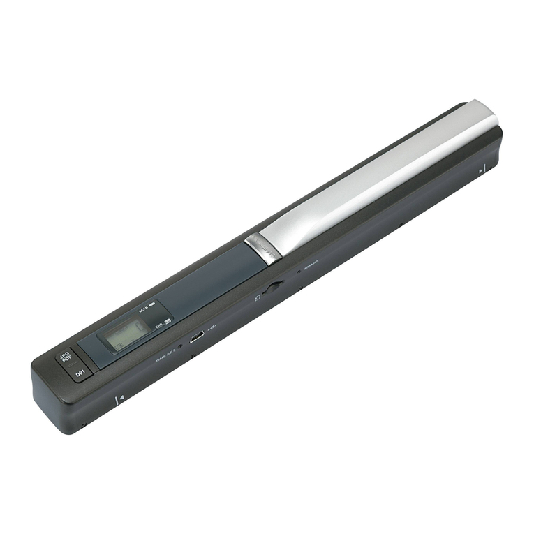
Autoobd AD100 User manual

- 1 -
AD100 SCANNER
User Manual

- 2 -
Table of Contents
-- Introduction ----------------------------------------------------------------------------
Product planation ---------------------------------------------------------------------------------- 3
Vehicle Service Information-------------------------------------------------------------------------5
Introduction to On-Board Diagnostics OBD II---------------------------------------------------6
-Diagnostic Link Connector (DLC) ----------------------------------------------------------- 8
-Data Link Connector (DLC) Pins------------------------------------------------------------- 9
-OBD II Diagnostic Trouble Codes (DTCs) -----------------------------------------------10
--Using The Scan Tool------------------------------------------------------------------
Keypad Functions -----------------------------------------------------------------------------------12
Display Functions -----------------------------------------------------------------------------------13
Getting Started ---------------------------------------------------------------------------------------14
Settings& Adjustments -----------------------------------------------------------------------------15
About …----------------------------------------------------------------------------------------------- 17
Malfunction Indicator Lamp (MIL)------------------------------------------------------------- 18
--Vehicle Diagnostic---------------------------------------------------------------------
SCAN CAR (Vehicle Diagnostic) ----------------------------------------------------------------19
1) READ DTCs-----------------------------------------------------------------------------22
2) ERASE DTCs---------------------------------------------------------------------------23
3) VIEW LIVE DATA----------------------------------------------------------------------24
-OBD-II GENERIC OPERATIONAL DATA ITEMS------------------------------ 25
-OBD-II GENERIC OPERATIONAL DATA ITEMS (CONT..) -----------------26
4) VIEW FREEZE FRAME--------------------------------------------------------------27
5) MIL STATUS ---------------------------------------------------------------------------28
6) I/M Readiness--------------------------------------------------------------------------29
7) VIEW VEHICLE INFORMATION--------------------------------------------------31
LAST SCAN ------------------------------------------------------------------------------------------32
Select M.F (SELECT MANUFACTORY) ------------------------------------------------------34
-SUPPORT MANUFACTORY---------------------------------------------------------------36
--Appendix---------------------------------------------------------------------------------
Appendix A – PID Definitions--------------------------------------------------------------------- 37
Appendix B – Glossary-----------------------------------------------------------------------------40
Common OBDII DTC Definitions reference---------------------------------------------------49

- 3 -
The Product is:
Scanner
OEM product
Product Features:
Codereader Codereader-Pro Scanner
Displays the DTC definitions on
screen unlike previous models Yes Yes Yes
Wider coverage: works with
CAN‐equipped vehicles Yes Yes Yes
Reads and clears all generic, and
some manufacturer, specific DTCs Yes Yes Yes
Resets check engine lights Yes Yes Yes
Views OBD‐II Freeze Frame data Yes Yes Yes
Determines the Malfunction
Indicator lamp (MIL) status No Yes Yes
Displays I/M readiness status No Yes Yes
Retrieves the Vehicle Identification
Number (VIN) No Yes Yes
Scanning live data No Yes Yes
Saves scanning Data Yes Yes Yes
PC Updata Software No No No

- 4 -
Features:
Display: 128x64 pixel LCD with contrast adjustment and backlight
Easy‐to‐Read screen and also saves up to 38 scans for later viewing.
Operating temperature:-20℃‐50 ℃(‐4℉to 122 ℉)
Operation Voltage : DC 9 ~15V provided by vehicle battery
Support Protocol:
1)SAE-J1850 PWM
2)SAE-J1850 VPW
3)ISO-14230
4)ISO-9141
5)ISO-15765-4 (CAN BUS)
Gting Started

- 5 -
Vehicle Service Information
The following is a list of web sites and phone numbers where electronic
engine control (EEC) diagnostic information is available.
Some manuals may be available at your local dealer, auto parts stores or local public
libraries.
Domestic Vehicles Web Site Phone Number
General Motors
Chevrolet www.chevrolet.com 1-800-551-4123
Pontiac Oldsmobile www.pontiac.com
www.oldsmobile.com 1-800-551-4123
1-800-551-4123
Buick www.buick.com 1-800-551-4123
Cadillac www.cadillac.com 1-800-333-4CAD
Saturn www.saturn.com 1-800-553-6000
Ford
Ford www.ford.com 1-800-392-3673
Lincoln www.lincoln.com 1-800-392-3673
Mercury
ChryslerChrysler Dodge
Plymouth Eagle
www.mercury.com
www.chrysler.com
www.dodge.com Not Available
Not Available
1-800-392-3673
1-800-348-4696
1-800-348-4696
1-800-348-4696
1-800-348-4696
European Vehicles
Audi www.audi.com 1-800-544-8021
Volkswagon BMW www.vw.com www.bmw.com 1-800-544-8021
1-201-307-4000
MINI www.mini.com 1-201-307-4000
Jaguar Volvo www.jaguar.com www.volvo.com 1-800-4-JAGUAR
1-800-458-1552
Mercedes-Benz www.mercedes-benz.com 1-800-367-6372
Land Rover www.landrover.com 1-800-637-6837
Porsche Saab www.porsche.com www.saab.com 1-800-PORSCHE
1-800-955-9007
Asian Vehicles Web Site Phone Number
Acura www.acura.com 1-800-999-1009
Honda www.honda.com 1-800-999-1009
Lexus www.lexus.com 1-800-255-3987
Scion www.scion.com 1.866.70.SCION
Toyota www.toyota.com 1-800-GO-TOYOTA
Hyundai www.hyundai.com 1-800-633-5151
Infiniti www.infiniti.com 1-800-662-6200

- 6 -
Nissan www.nissanusa.com 1-800-nissan1
Kia www.kia.com 1-800-333-4542
Mazda www.mazda.com 1-800-222-5500
Daewoo www.daewoo.com 1-822-759-2114
Subaru www.subaru.com 1-800-SUBARU3
Isuzu www.isuzu.com 1-800-255-6727
Geo Not Available Not Available
Mitsubishi www.mitsubishi.com 1-888-MITSU2004
Suzuki www.suzukiauto.com 1-800-934-0934

- 7 -
Introduction to On-Board Diagnostics OBD II
On-board diagnostics version II (OBD II) is a system that the Society of
Automotive Engineers (SAE) developed to standardize automotive
electronic diagnosis.
Beginning in 1996, most new vehicles sold in the United States were
fully OBD II compliant.
Technicians can now use the same tool to test any OBD II
compliant vehicle without special adapters. SAE established
guidelines that provide:
A universal connector, called the DLC, with dedicated pin
assignments.
A standard location for the DLC, visible under the dash on
driver’s side.
A standard list of diagnostic trouble codes (DTCs) used by
all manufacturers.
A standard list of parameter identification (PID) data used
by all manufacturers.
Ability for vehicle systems to record operating conditions
when a fault occurs.
Expanded diagnostic capabilities that records a code
whenever a condition occurs that affects vehicle emissions.
Ability to clear stored codes from the vehicle’s memory with
a Scan Tool.
SAE Publications
SAE has published hundreds of pages of text defining a standard
communication protocol that establishes hardware, software, and
circuit parameters of OBD II systems.
• SAE publishes recommendations, not laws, but the Environmental
Protection Agency (EPA) and California Air Resources Board
(CARB) made many of SAE’s recommendations legal requirements.

- 8 -

- 9 -

- 10 -
Within each category (Powertrain, Chassis, Body and Network) of
DTCs there are assigned ranges for different vehicle systems.

- 11 -

- 12 -
Keypad Functions:
Power button,ON or OFF Scan Tool.
Enter button,to perform the selected
function of the menu.
NO button,for cancelling the operation
Or return back by pressing this button.
Help button,explain the abbr letters during operation .
Note: Using the Help button always when you have any doubts of the
operation or abbr letters, that would improve your work more efficient.
Page-Up roll button
Page-Down roll button

- 13 -
Display Functions:
①Diagnostic Trouble Codes Display Area.
When the DTC reader found a fault code in the
PCM, it will display here. Each fault is assigned
a code number that is specific to the fault.
②PENDING Icon:
Indicates the currently display DTC is a
“Pending” Code.
③DTC Definitions:
Information on DTC definitions, Freeze Frame
data and test messages are displayed here.
④DTC Number Sequence:
The DTC reader assigns a code sequence number to each DTC found in the
vehicle’s PCM. The sequence will start from 1. This number will indicate which
code is currently displayed. / DTC Enumerator Indicates the total number of
codes retrieved from the vehicle’s ECU.
⑤G/E instruction:
Generic DTC / Enhanced DTC
⑥Link Icon:
Indicates whether that the DTC Reader is communicating
with the vehicle’s computer or not.
⑦LED instruction:
Color changing display to indicate the Scan Tool system status.
RED-SYSTEM Working
YELLO- Establish a communication with the vehicle

- 14 -
Getting Started:
Before you use Scan Tool on the vehicle, please ensure that mechanical problems such
as low oil level, damaged hoses, wiring or electrical connections are fixed FIRST. They
may cause a fault code to set.
The following Areas need to be checked before starting any test:
¾The levels of engine oil, power steering fluid, transmission fluid (if auto
transmission), engine coolant and other fluids must be at proper level. Top up if
necessary.
¾Check the condition of air hoses and the air filter must be cleaned. Replace if
necessary.
¾Make sure the timing belts are in good condition and properly tensioned.
¾Make sure the spark plugs are cleaned and in good condition. Check for loose,
damaged, disconnected or missing plug cables.
¾Make sure that all mechanical linkages to the engine sensors (throttle, gearshift
position, transmission, etc) are secure and properly connected. Refer to Service
Manuals for locations.
¾Check all electrical wirings and harnesses for proper connections and condition of
its insulation.
¾Check all rubber hoses (radiator) and steel hoses (vacuum and fuel) for leaks,
cracks, blockage or other damages.
¾Make sure the engine is mechanically sound. Do a compression check, engine
vacuum check, timing check, etc.
¾Always refer to the manufacturer’s Service Manual
if you are not sure of the repair procedures.

- 15 -
Settings & Adjustments
To enter the MENU Mode:
1、Once the Scan Tool is powered up through the DLC connection,Press .
button, the wake up screen will display as below:
2、After a few seconds, it will switch to:
3、Press OR button, the screen will change to:

- 16 -
4、Press button, the screen will change to:
5、Press button, the screen will change to:
6、Press button, the screen will change to:
7、Press or button, button to increase or decrease the brightness
ranges from 1 to 9.
8、Once the brightness adjustment had been selected to your desired setting, press
YES button to exit to the main Menu.
9、To exit totally, press button, Exit Menu.

- 17 -
About …
Enter the Setting Menu,
Press button.
The screen will change to:
Press or button
:
The screen will change to
Press button.
The screen will change to:
SW:Scan tool Software Number
HW:Scan tool Hardware Number
SN: Scan tool Serial Number
DTC Loaded: DTC Loaded quantity
To exit totally, press button, Exit Menu.

- 18 -
Malfunction Indicator Lamp (MIL):
When the vehicle on board computer detects a problem in the emission related
systems or components, its diagnostic program will assign a fault code (DTC) and
store it in its memory. It also records a “Freeze Frame” of the conditions present
when the fault was found and set the malfunction indicator lamp (MIL) alight. Some
faults require detection
for two trips in a row before the MIL is turned on.
Three typical examples of MIL are shown below:
Definition of Trip
‘A Trip’ is define as a Key-ON, Key-OFF event in which the powertrain control
module (PCM) detects the following:
• Engine coolant temperature should exceed 70oC
• Engine coolant temperature should change more than 20oC after starting the
engine.
• Engine speed should go over 400 RPM.
When the powertain control module (PCM) detects a fault during the 1st trip, the DTC
and the corresponding ‘Freeze Frame’ data are stored in the PCM’s memory. The
MIL will not light up until the fault is again detected during the 2nd trip. Certain DTCs
are
capable of turning the MIL on or blinking during the first trip.

- 19 -
Vehicle Diagnostic
When everything had been confirmed and checked as mentioned in Getting Started, the
testing operation can be carried out.
1. Locate the vehicle Diagnostic
Link Connector (DLC) and
make sure that the ignition
switch is in OFF position.
2. Connect the Scan Tool cable
connector to the vehicle’s DLC.
• If problem of connecting,
rotate it to 180o and try again.
3. When the connection has been established, Press button,
the Scan tool will light up and it will display as below:

- 20 -
4. After a few seconds, it will switch to:
5. If the vehicle Diagnostic Protocol is
OBD-II,But the DTC Code is
MANUFACTORY,Please press UP or
DN button,then press yes , the screen
will change to:
Or else, Press NO,forget this step and
Select MF
6.Turn the ignition on.
DO NOT start the engine.
7.Press the button once, the
Scan tool will automatically start to
communicate the ECU of vehicle
and search which type of
communication protocol is using.
Once the Scan tool identifies the
computer’s communications
protocol, a communication link is
established.
The protocol type will be shown on
the LCD display.
Table of contents
