AutoPulse 100 User manual

P/N. 10762-001 Rev. 5-24-07
Resuscitation System Model 100
Battery Charger User Guide

Page ii P/N. 10762-001 Rev. 5-24-07
Battery Charger User Guide
Notice
About this Guide
The information in this User Guide applies to the ZOLL Circulation AutoPulse®Battery Charger
designed for the AutoPulse Resuscitation System Model 100. The AutoPulse Power System consists of
two main components: the AutoPulse Battery Charger (also known as the Battery Charger) and the
AutoPulse Battery (also known as the Battery).
ZOLL Circulation shall not be liable for errors contained herein or for incidental or consequential
damages in connection with the furnishing, performance, or use of this material.
Copyright
© Copyright ZOLL Circulation 2007. All rights reserved.
No part of this publication may be reproduced, stored in a retrieval system, or transmitted, in any form
or by any means, mechanical, electronic, photocopying, recording, or otherwise, without prior written
permission of ZOLL Circulation.
AutoPulse and LifeBand®are trademarks of ZOLL Circulation. All other trademarks mentioned herein
belong to their respective owners.
86$
=2//&LUFXODWLRQ
+XPEROGW&RXUW
6XQQ\YDOH&$86$
W
I
(8$XWKRUL]HG5HSUHVHQWDWLYH
=2//,QWHUQDWLRQDO+ROGLQJ%9
(GLVRQULQJD
1$'RGHZDDUG
7KH1HWKHUODQGV
W
0344

P/N. 10762-001 Rev. 5-24-07 Page iii
Battery Charger User Guide
Table of Contents 0
Figures .....................................................................................................................iv
Tables ........................................................................................................................v
Preface ....................................................................................................................vii
Who Should Read this Guide ................................................................................vii
General Warnings and Precautions ......................................................................vii
Symbols .................................................................................................................viii
1 Introduction of the AutoPulse Power System ................................................1-1
%DWWHU\&KDUJHU&RPSRQHQWV
%DWWHU\
%DWWHU\&KDUJHU
2 Setting Up the AutoPulse Battery Charger .....................................................2-1
3 Performing a Battery Status Check .................................................................3-1
4 Operating the Battery Charger ........................................................................4-1
2SHUDWLQJ6HTXHQFH
8QGHUVWDQGLQJ7HVW&\FOHV
5 Managing the AutoPulse Power System .........................................................5-1
%DWWHU\0DQDJHPHQW
%DWWHU\0DLQWHQDQFH
6WRULQJ%DWWHULHV
5HDFKLQJWKH(QGRI%DWWHU\6HUYLFH/LIH
'LVSRVLQJRI1LFNHO0HWDO+\GULGH%DWWHULHV
%DWWHU\&KDUJHU0DLQWHQDQFH
&OHDQLQJWKH%DWWHU\&KDUJHU
5HSODFLQJD%DWWHU\&KDUJHU)XVH
Appendix A Troubleshooting ............................................................................. A-1
Appendix B Technical Specifications ..................................................................B-1
%%DWWHU\3K\VLFDO %
%%DWWHU\(QYLURQPHQWDO %
%%DWWHU\&KDUJHU3K\VLFDO%
%%DWWHU\&KDUJHU(QYLURQPHQWDO%
%)&&6WDWHPHQW%
%/LPLWHG:DUUDQW\IRU$XWR3XOVH5HVXVFLWDWLRQ6\VWHP%
Index .......................................................................................................................I-1

Page iv P/N. 10762-001 Rev. 5-24-07
Battery Charger User Guide
Figures 0
)LJXUH$XWR3XOVH6\VWHP
)LJXUH$XWR3XOVH3RZHU6\VWHP&RPSRQHQWV
)LJXUH$XWR3XOVH6\VWHP%DWWHU\
)LJXUH$XWR3XOVH%DWWHU\&KDUJHU
)LJXUH%DWWHU\6WDWXV&KHFN%XWWRQDQG6WDWXV/('V
)LJXUH6OLGLQJWKH%DWWHU\LQWRD&KDUJLQJ%D\
)LJXUH%DWWHU\&KDUJHU)XVH/RFDWLRQ

P/N. 10762-001 Rev. 5-24-07 Page v
Battery Charger User Guide
Tables 0
7DEOH%DWWHU\6WDWXV/('V
7DEOH%DWWHU\&KDUJHU6WDWXV/('V
7DEOH$%DWWHU\7URXEOHVKRRWLQJ3URFHGXUHV $
7DEOH$%DWWHU\&KDUJHU7URXEOHVKRRWLQJ3URFHGXUHV $
7DEOH%%DWWHU\6SHFLILFDWLRQV %
7DEOH%%DWWHU\6SHFLILFDWLRQV %
7DEOH%%DWWHU\(0,(0&6SHFLILFDWLRQV %
7DEOH%%DWWHU\&KDUJHU3K\VLFDO6SHFLILFDWLRQV %
7DEOH%%DWWHU\&KDUJHU(QYLURQPHQWDO6SHFLILFDWLRQV %
7DEOH%%DWWHU\&KDUJHU(0,(0&6SHFLILFDWLRQV %

Page vi P/N. 10762-001 Rev. 5-24-07
Battery Charger User Guide
[This page left intentionally blank.]

P/N. 10762-001 Rev. 5-24-07 Page vii
Battery Charger User Guide
Preface 0
This document describes the operating steps and maintenance requirements for the AutoPulse Power
System for use as part of the AutoPulse Resuscitation System Model 100. The AutoPulse Power System
consists of two main components: the AutoPulse Battery Charger (also known as the Battery Charger)
and the AutoPulse Battery (also known as the Battery).
Proper use of the AutoPulse Power System requires a thorough understanding of the Power System, and
appropriate training and practice using the Power System.
Please read the entire User Guide for the AutoPulse Battery Charger and User Guide for the AutoPulse
System before using the Battery and Battery Charger.
Who Should Read this Guide 0
This document should be read by personnel who are tasked with the care and maintenance of the Battery
Charger and the Battery used to operate the AutoPulse System.
General Warnings and Precautions 0
Caution: United States federal law restricts this device to sale by or on the order of a licensed physician.
Caution: The AutoPulse System is designed to be used only with ZOLL Circulation-approved
accessories. The AutoPulse System will perform improperly if non-approved accessories are
used.
Caution: Only use ZOLL Circulation Batteries specifically designed for use with the AutoPulse
System. The use of other batteries may cause permanent damage to the AutoPulse Platform
and will void the warranty.
Caution: Do not short the Battery Power leads. Electrical connection (short) between Battery power
leads on the connector permanently damages the Battery and renders the Battery inoperable.
Caution: Always charge Batteries at temperatures between 41ºF (5ºC) and 95ºF (35ºC). Charging
Batteries at temperatures below 41ºF (5ºC) or above 95ºF (35ºC) will prevent the Battery from
reaching its full capacity (operational time) and may lead to irreversible Battery damage.
Warning:
•Always charge a new Battery. Failure to charge a Battery may cause reduced Battery
performance.
•Always charge a stored Battery before placing the Battery in active operation. Battery may
self-discharge when not in use. Failure to charge a Battery before use may cause device
power failure.
Page viii P/N. 10762-001 Rev. 5-24-07
Battery Charger User Guide
Caution: Do not use Batteries that have cracks in the Battery case exposing internal components.
Mishandling of the Battery may lead to physical damage and present a fire or shock hazard.
Caution: Do not immerse any portion of the AutoPulse Battery in water or other fluids. Do not allow
fluids to enter the Battery or the Battery connector. Fluid immersion or spillage may
permanently damage the Battery or present a fire or shock hazard.
Caution: Do not heat, burn, or incinerate a Battery. Exposure to heat above 158ºF (70ºC) may
irreversibly damage the Battery.
Caution: Do not attempt to open the Battery. The Battery has no serviceable parts.
Caution: Do not block the Battery Charger’s ventilation slots.
Caution: Remove the protective plastic cap from the Battery before attempting to charge the Battery.
Caution: Do not operate the Battery Charger in a confined space.
Caution: Keep the Battery Charger away from moisture.
Caution: Do not remove the Battery Charger cover. The Battery Charger has no internal user-
serviceable parts.
Caution: Use the Battery Charger only with ZOLL Circulation AutoPulse Battery Charger power cord,
as supplied.
Caution: Grounding reliability can only be achieved when the Battery Charger is connected to an
equivalent receptacle marked “hospital only” or “hospital grade.”
Symbols 0
The symbols below may be found in this User Guide, on the AutoPulse Battery Charger, or on the
AutoPulse Battery.
With Respect to Electric Shock, Fire, Mechanical
and other specified Hazards Only.
In accordance with CAN/CSA C22.2 NO. 601.1,
(CAN/CSA 601.2XX, If Applicable)
Medical Equipment Certified for Canada
6SA9
With Respect to Electric Shock,
Fire and Mechanical Hazards Only
In Accordance with UL 2601-1
6SA9
Attention: Consult Accompanying Documents
Indoor Use Only
UL
C
L
A
S
S
I
F
I
E
D
C US
®
UL
C
L
A
S
S
I
F
I
E
D
C US
®
!
P/N. 10762-001 Rev. 5-24-07 Page ix
Battery Charger User Guide
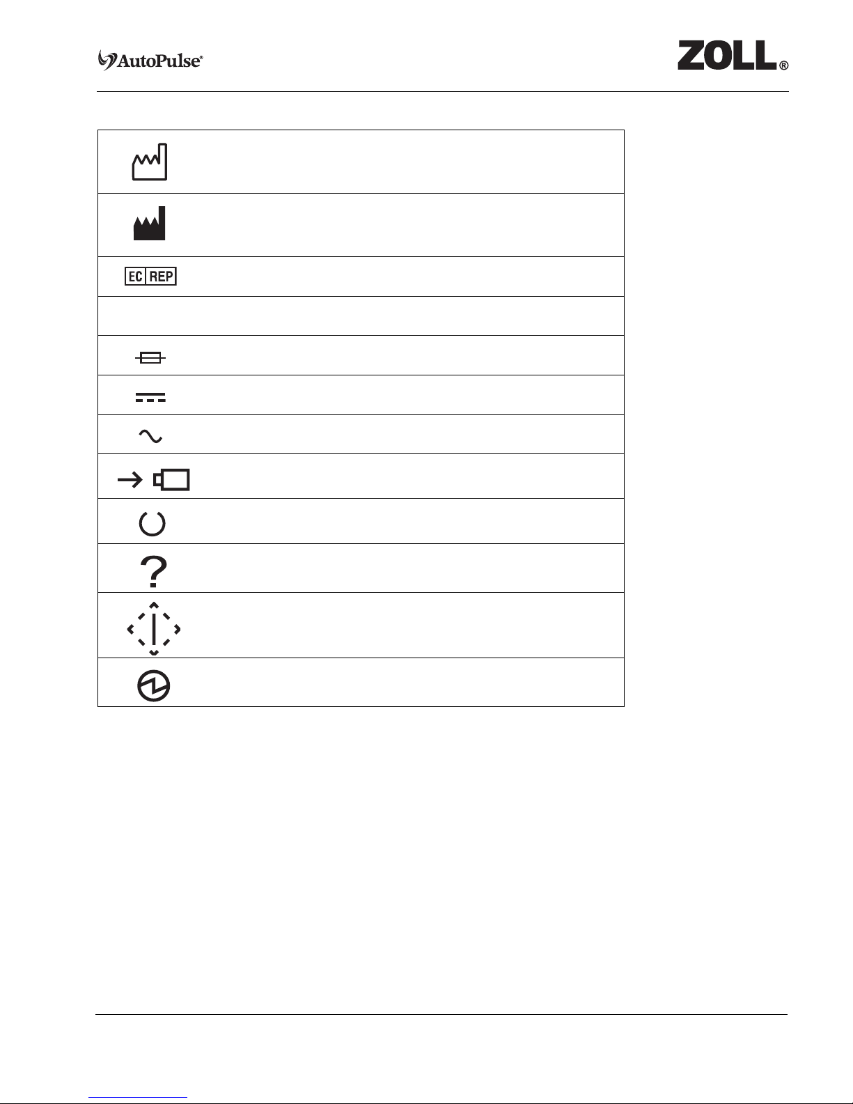
Date of Manufacture
Manufacturer
EU Authorized Representative
Serial Number
Fuse
DC Voltage
AC Voltage
Charging
Ready
Fail
Start Test
Power
SN

Page x P/N. 10762-001 Rev. 5-24-07
Battery Charger User Guide
[This page left intentionally blank.]
P/N. 10762-001 Rev. 5-24-07 Page 1-1
Battery Charger User Guide
1 Introduction of the AutoPulse Power System
The AutoPulse Power System represents a state-of-the-art breakthrough in battery technology and one
of the breakthroughs that make the AutoPulse Resuscitation System possible (see Figure 1-1). The
AutoPulse Battery communicates with the AutoPulse Battery Charger or with the AutoPulse Platform
when it is plugged into each respectively.
The Battery is intended to operate for a minimum of 30 minutes at a rate of 80 compressions per
minute.
The Battery uses nickel-metal hydride (NiMH) technology because NiMH delivers one of the highest
power outputs of any battery technology. At the same time, NiMH does not have the limiting memory
effect inherent with nickel-cadmium (NiCd) batteries or the higher weight associated with the higher
mass-to-power ratio of lead-acid batteries. The Battery automatically monitors its readiness state. As a
result, no paper battery-management systems are required to track battery status. Finally, the Battery is
mechanically keyed to the AutoPulse Platform and Battery Charger to facilitate correct installation.
Figure 1-1 AutoPulse System
LifeBand
AutoPulse Platform
Battery ChargerUser Control Panel
Batteries
(Primary and Spare)
Page 1-2 P/N. 10762-001 Rev. 5-24-07
Battery Charger User Guide
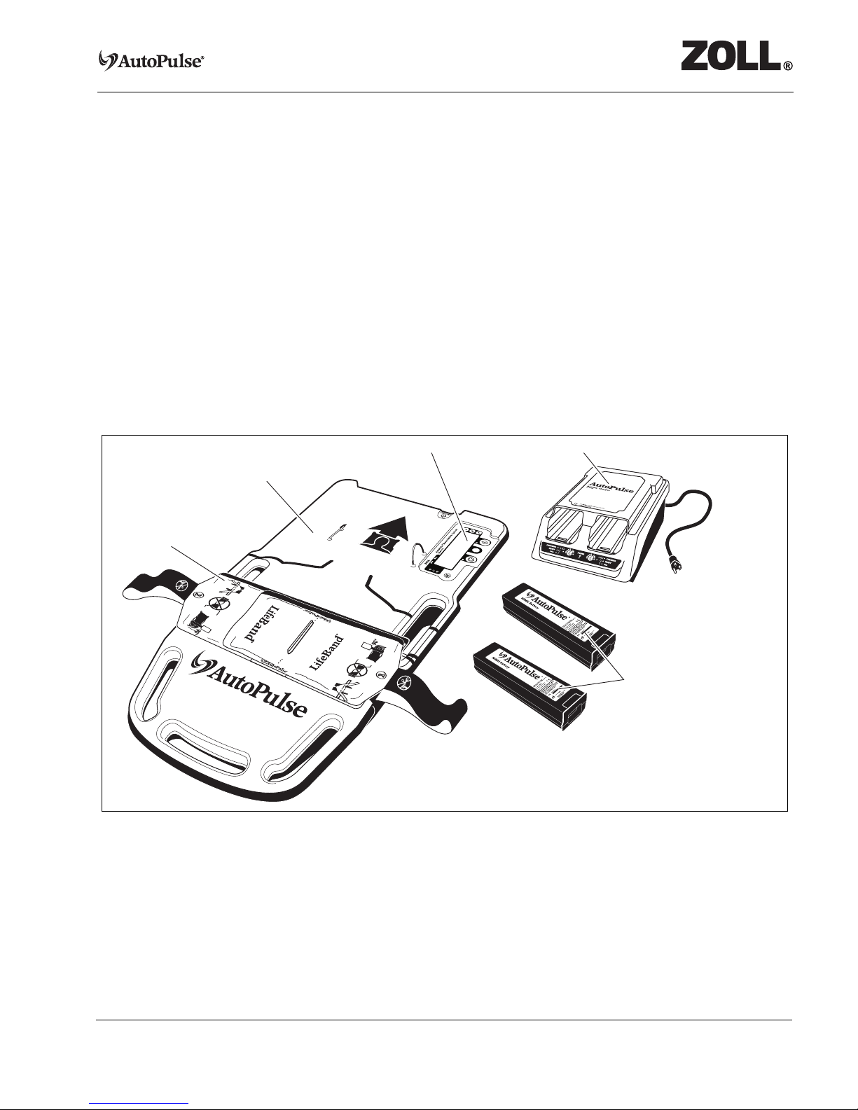
1.1 Battery Charger Components
Figure 1-2 shows the components of the AutoPulse Power System.
Figure 1-2 AutoPulse Power System Components
The AutoPulse Power System consists of the following components:
•Battery
•Battery Charger, includes power cord
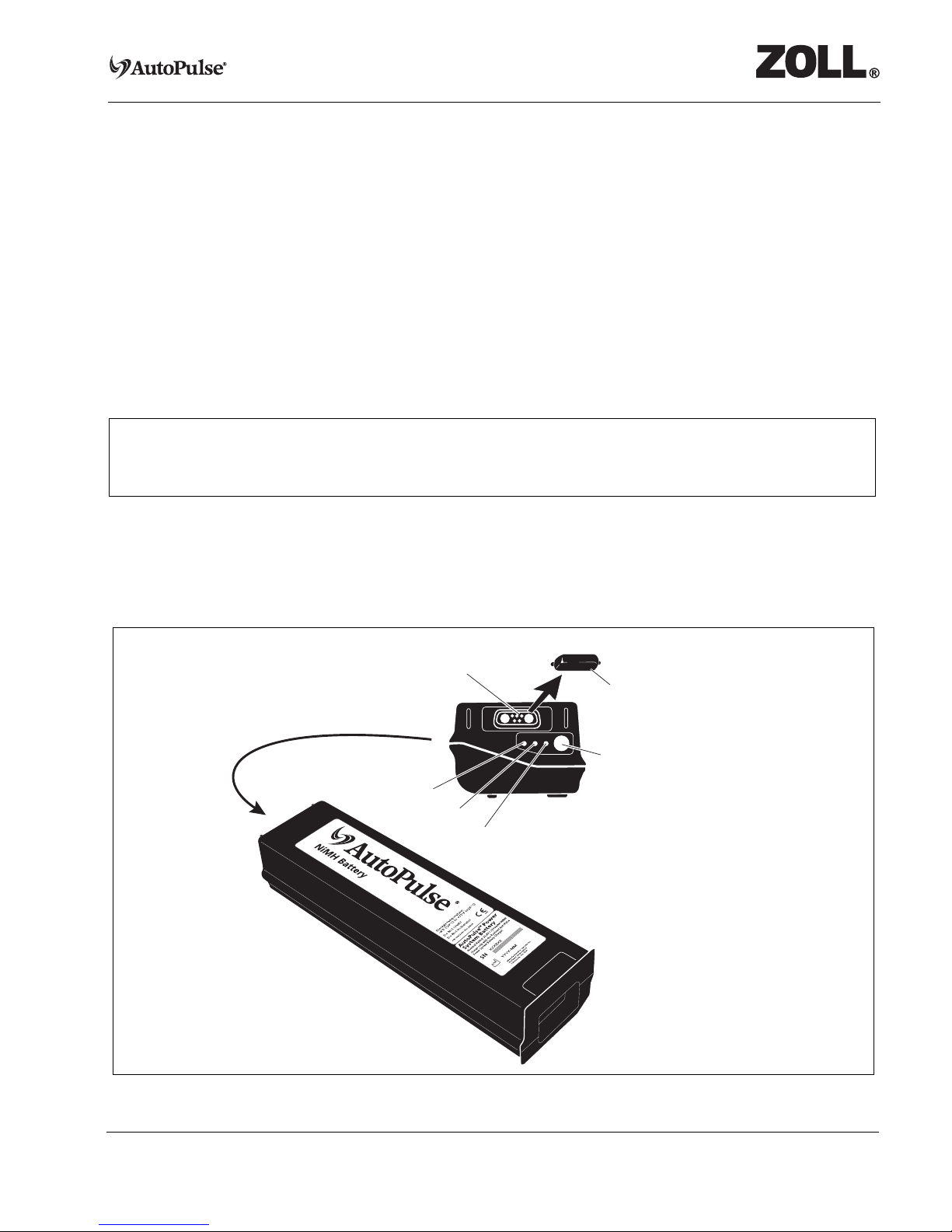
1.1.1 Battery
The Battery (see Figure 1-3) is a removable component that supplies power for the AutoPulse Platform
operation. The Battery is a proprietary, rechargeable, nickel-metal hydride (NiMH) battery that is the
exclusive power source for the AutoPulse Platform.
Battery Charger
Battery Charger
Batteries
P/N. 10762-001 Rev. 5-24-07 Page 1-3
Battery Charger User Guide
The Battery is mechanically keyed to the AutoPulse Platform and Battery Charger to facilitate correct
installation. The Battery’s back end contains connections for power and communications. A Battery
Status Check button illuminates the Battery’s status light-emitting diodes (LEDs).
A single Battery may perform as many as 100 charge/discharge cycles before the Battery reaches the end
of its service life. The Battery charge/discharge cycle count increments when the Battery Charger detects
that the Battery has been discharged more than 1/3 of its capacity (shallow discharge/recharge cycles will
not increment the cycle count).
Checking the Battery’s status allows you to determine the need for a charge to ensure adequate battery
capacity (run time). A green LED ensures that the Battery has the capacity for a minimum run time of
30 minutes on a typical patient. Batteries self-discharge when not in use. Recharge the Battery before use
if the amber LED illuminates (see Figure 1-3).
Caution: Remove the protective plastic cap from the Battery before attempting to charge the Battery.
Caution: Only use ZOLL Circulation Batteries specifically designed for use with the AutoPulse
System. The use of other batteries may cause permanent damage to the AutoPulse Platform
and will void the warranty.
Figure 1-3 AutoPulse System Battery
Warning: Always charge a stored Battery before placing the Battery in active operation. Battery may
self-discharge when not in use. Failure to charge a Battery before use may cause device
power failure.
Status Check Button
Power and Communications
Red LED
Amber LED
Green LED
Remove Protective
Plastic Cap before use
Page 1-4 P/N. 10762-001 Rev. 5-24-07
Battery Charger User Guide
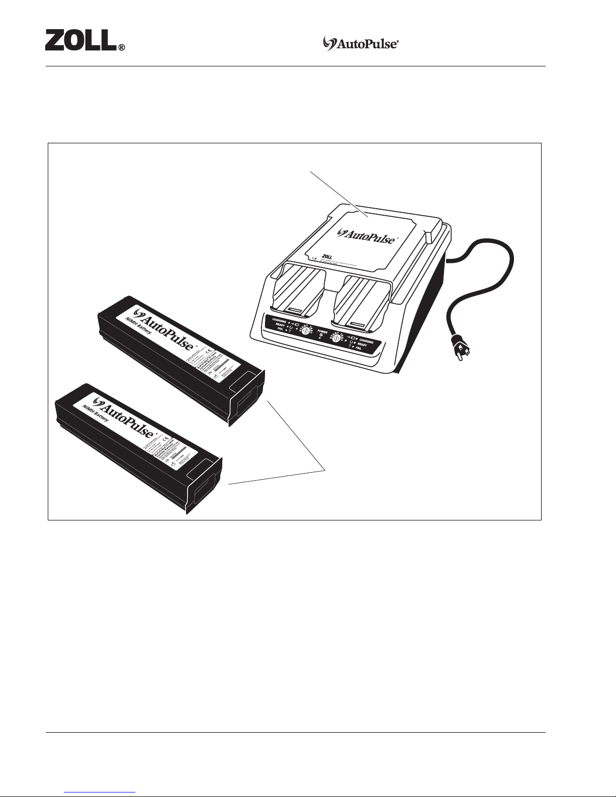
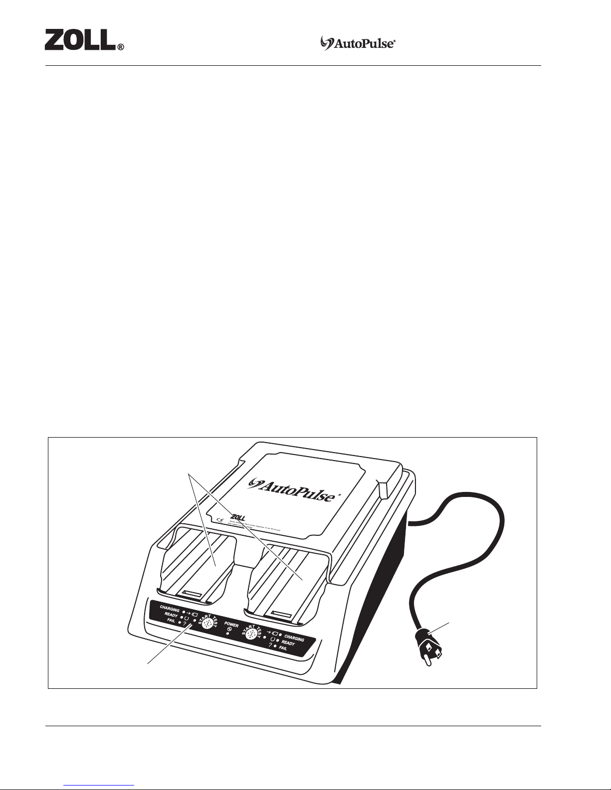
1.1.2 Battery Charger
The Battery Charger is a stand-alone unit intended to charge and test-cycle the Batteries (see Figure 1-
4). The Battery Charger has two charging bays; each with its own indicators. The Battery Charger
automatically maintains both the state of charge and tests and maintains the Battery to its highest possible
capacity. Batteries should always be fully charged and ready for use before deploying the AutoPulse
Platform.
Batteries placed in a charging bay are automatically charged (CHARGING LED illuminated) in less than
4 1/4hours (maximum).
To maintain the Battery, the AutoPulse Battery Charger design incorporates a test-cycle mode. The test-
cycle measures the Battery’s charge-holding capability by cycling the Battery through a charge-
discharge-recharge sequence.
Batteries that pass the test remain ready for use. Batteries that fail the test undergo additional test-cycles
to attempt to restore the Battery. After three test cycles, the Battery either is restored to READY (green
LED on Battery) or has failed and should be replaced (red LED on Battery). The normal test-cycle
requires approximately 10 hours. The maximum test-cycle is approximately 30 hours if all three test-
cycles are performed.
The Battery Charger’s test-cycle mode is activated in two ways:
•Automatically at every 10th charge.
•Manually when the user presses the Start Test button on the Battery Charger Control Panel during
routine charging (amber LED).
Figure 1-4 AutoPulse Battery Charger
User Control Panel
Battery Charging Bays
AC Power Cord,
as supplied
Battery Charger

P/N. 10762-001 Rev. 5-24-07 Page 2-1
Battery Charger User Guide
2 Setting Up the AutoPulse Battery Charger
The AutoPulse Battery Charger must be installed near the wall outlet to which it is connected and that
outlet must be easily accessible at all times. Unplug the power cord from the wall outlet to remove power
from the Battery Charger.
Caution: Do not block the Battery Charger’s ventilation slots.
Caution: Do not operate the Battery Charger in a confined space.
Caution: Keep the Battery Charger away from moisture.
Caution: Use the Battery Charger only with ZOLL Circulation AutoPulse Battery Charger power cord.
Caution: Grounding reliability can only be achieved when the Battery Charger is connected to an
equivalent receptacle marked “hospital only” or “hospital grade.”
To prepare the Battery Charger for use:
1. Plug the alternating current (AC) power cord into the power receptacle on the back of the Battery
Charger.
2. Plug the AC power cord into an appropriate wall outlet receptacle.
When the POWER indicator (green LED) on the Battery Charger’s Control Panel illuminates, the
Battery Charger is ready for use.
If, after properly plugging in the Battery Charger, the green Power light on the Control Panel does not
illuminate, read Section 5.3.2, “Replacing a Battery Charger Fuse”.
Note: When powering up the Battery Charger, all indicators on the Control Panel will illuminate
briefly to provide a visual check that the indicator lights are functioning. If an indicator fails to
illuminate, contact ZOLL Circulation.

Page 2-2 P/N. 10762-001 Rev. 5-24-07
Battery Charger User Guide
[This page left intentionally blank.]

P/N. 10762-001 Rev. 5-24-07 Page 3-1
Battery Charger User Guide
3 Performing a Battery Status Check
To determine if an AutoPulse Battery needs to be charged, press the Status Check button on the Battery
(see Figure 3-1).
Figure 3-1 Battery Status Check Button and Status LEDs
One of the following Battery status light-emitting diodes (LEDs) will illuminate (refer to Table 3-1).
Table 3-1 Battery Status LEDs
Status LEDs Definition Action
Green The Battery is charged and ready for use. No action is necessary.
Amber/
amber-flashing
The Battery is partially discharged.
Remaining runtime is unknown.
Charge the Battery.
Refer to Chapter 4, “Operating the Battery
Charger” for more information.
Red-flashing The Battery has
•Exceeded its service life.
•Failed a test-cycle.
The Battery has failed and should not be used.
Refer to Section 5.2.3, “Disposing of Nickel-Metal
Hydride Batteries” for more information.
None The Battery voltage is too low because
the Battery has failed or has been
overused.
Test-cycle the Battery. Refer to Section 4.2,
“Understanding Test-Cycles” for more
information.
Status Check Button
Red
LED
Amber
LED
Green
LED

Page 3-2 P/N. 10762-001 Rev. 5-24-07
Battery Charger User Guide
[This page left intentionally blank.]

P/N. 10762-001 Rev. 5-24-07 Page 4-1
Battery Charger User Guide
4 Operating the Battery Charger
4.1 Operating Sequence
You should place the AutoPulse Battery into an available charging bay:
•Following each use.
•When the Battery’s amber status light-emitting diode (LED) illuminates or flashes.
•To maintain a charge on any spare Battery.
Caution: Remove the protective plastic cap from the Battery before attempting to charge the Battery.
One or two Batteries placed in a charging bay are automatically charged (yellow CHARGING LED will
illuminate) in less than 4 1/4hours.
To charge a Battery, follow these steps:
Note: For optimal charging, make sure that the Battery and Battery Charger are at room
temperature (68º to 77ºF [20º to 25ºC]).
Note: Do not slam the Battery into the Battery Charger because doing so may cause damage to
the Battery’s connector.
Note: The Battery is mechanically keyed so that it can only be inserted in one orientation. Do
not force the Battery into the charging bay. If resistance is met, check for appropriate
orientation, and check to ensure that there are no obstructions to Battery insertion.
Warning: Always charge a new Battery. Failure to charge a Battery may cause reduced Battery
performance.
Page 4-2 P/N. 10762-001 Rev. 5-24-07
Battery Charger User Guide
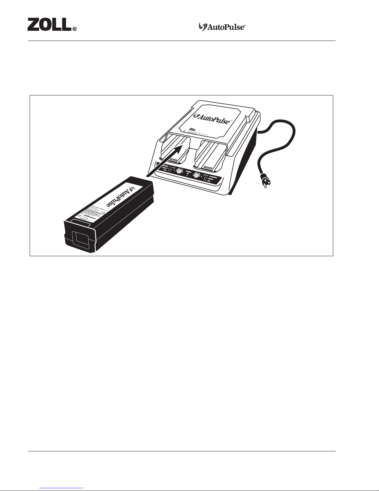
1. Slide the Battery into an available charging bay (see Figure 4-1). Ensure that the Battery locks into
place (locking bar engaged).The Battery Charger’s status will be indicated on the Control Panel.
Table 4-1 shows the information given by the charging status LEDs for each charging bay when the
POWER LED is illuminated.
Figure 4-1 Sliding the Battery into a Charging Bay
2. The CHARGING LED will automatically illuminate when the Battery Charger identifies a
functional Battery.
Note: If the FAIL LED illuminates following Battery insertion into the charging bay, refer to
Appendix A, “Troubleshooting” for more information.
3. The TEST LED will automatically illuminate when a Battery requires a test-cycle. Refer to Section
4.2, “Understanding Test-Cycles” for more information.
Note: To manually start a test-cycle on a Battery, press the Start Test button.
4. The READY LED will illuminate after successfully charging the Battery (41/4 hours maximum).
Battery Charger
NiMH Battery
Table of contents
Popular Batteries Charger manuals by other brands


 Instructions for use")

Shell
Shell Advanced View 2.2 owner's manual

Professional
Professional 954442 instruction manual

YATO
YATO YT-83033 Operating instruction

Project EV
Project EV Dual Wall Pro Earth user manual

Tronic
Tronic 74183 operating instructions

National Railway Supply
National Railway Supply ELC-24/10-M-D Installing, operating and service instructions


