Avalon Arbor User manual

A r b o r
Wood Stove
Owner's Manual
• Freestanding Stove
• Mobile-Home Approved
• Alcove Approved
• Hearth-Stove Approved
Save these instructions
for future reference
SAFET NOTICE:
If this appliance is not properly installed, a house fire may
result. For your safety, follow the installation directions.
Contact local building or fire officials about restrictions and
installation inspection requirements in your area.
4800 arbour Pointe Blvd. SW
Mukilteo, WA 98275
Copyright 2007, T.I.
$10.00 100-01190_000
4070326 Listed
Tested to: U.L. 1482
Test Report # 028-S-75-2

2 Introduction
© Travis Industries 100-01190_000 4070326
Introduction
We welcome you as a new owner of an Arbor wood-burning stove. In purchasing an Arbor you have
joined the growing ranks of concerned individuals whose selection of an energy system reflects both a
concern for the environment and aesthetics. The Arbor is one of the finest appliances the world over.
This manual will explain the installation, operation, and maintenance of this appliance. Please familiarize
yourself with the Owner's Manual before operating your appliance and save the manual for future
reference. Included are helpful hints and suggestions which will make the installation and operation of
your new appliance an easier and more enjoyable experience. We offer our continual support and
guidance to help you achieve the maximum benefit and enjoyment from your appliance.
Important Information
No other Avalon Arbor appliance has the same serial
number as yours. The serial number is stamped onto
the label on the back of the appliance.
This serial number will be needed in case you require
service of any type.
Model: Avalon Arbor
Serial Number:
Purchase Date:
Purchased From:
Register your warranty online at:
traviswarranty.com
Or, mail your warranty card to:
Travis Industries ouse of Fire
4800 arbour Pointe Blvd. SW
Mukilteo, WA 98275
Save our Bill of Sale.
To receive full warranty coverage, you will
need to show evidence of the date you
purchased your heater. Do not mail your Bill
of Sale to us.
We suggest that you attach your Bill of Sale
to this page so that you will have all the
information you need in one place should the
need for service or information occur.

Table of Contents 3
© Travis Industries 100-01190_000 4070326
General Information
Introduction & Important Information...................... 2
afety Precautions ............................................ 4
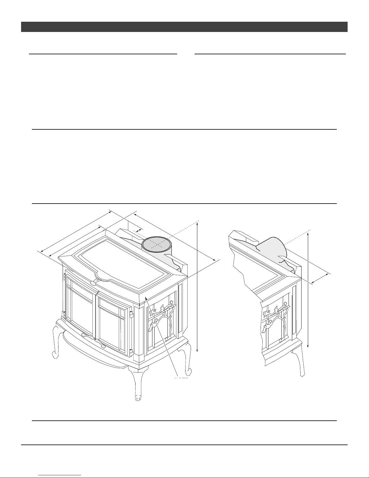
Features & pecifications.................................... 6
Stove Installation
Planning the Installation...................................... 7
Preparation for Installation..............................7
Stove Installation Considerations .....................7
Floor Protection Requirements ............................. 8
tove Placement Requirements ........................... 8
Clearances ...................................................... 8
Top View - Straight Installation ........................9
Top View - Corner Installation ......................... 9
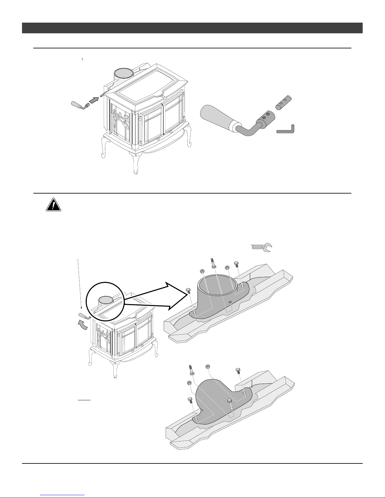
Bypass Handle Installation .................................. 10
Rear Vent Configuration ..................................... 10
Chimney Connector Requirments ......................... 11
Chimney Requirements ...................................... 12
Chimney Termination Requirements...................... 13
Outside Air Requirements ................................... 13
Alcove Installation Requirements .......................... 14
Mobile Home Requirements ................................ 15
INSTALLATION DIAGRAMS
Standard Ceiling with a Factory Built Chimney....16
Cathedral Ceiling with a Factory Built Chimney... 16
Hearth Stove Positive Connection....................17
Hearth Stove Direct Connection.......................17
Interior or Exterior Masonry Chimney................18
Operating Your Applian e
afety Notice.................................................... 19
Operating the Stove when it is Hot ...................19
Before Your First Fire ......................................... 19
Curing the Paint ........................................... 19
Over-Firing the Stove .................................... 19
Opening the Doors ............................................ 20
Bypass Operation.............................................. 21
Loading Lid Operation ........................................ 21
tarting a Fire................................................... 22
Adjusting the Burn Rate ...................................... 23
Approximate Air Control Settings ..................... 23
Operating Your Applian e ( ontinued)
Ash Removal.................................................... 24
Ashpan Removal..........................................24
Blower Operation .............................................. 25
Re-Loading the tove......................................... 25
Overnight Burn ................................................. 25
Normal Operating ounds ................................... 25
Hints for Burning ............................................... 26
electing Wood................................................. 26
Why Dry Wood is Key....................................26
Wood Cutting and Storage.............................. 26
Troubleshooting ................................................ 27
Maintaining Your Applian e
Daily Maintenance (while stove is in use) ............... 28
Remove Ash (if necessary).............................28
Clean the Glass (if necessary).........................28
Monthly Maintenance (while appliance is in use) ...... 29
Door and Glass Inspection.............................. 29
Creosote - Formation and Need for Removal......29
Yearly Maintenance ........................................... 30
Touch Up Paint ............................................30
Cleaning the Air Duct and Blower (if applicable).. 30
Door Parts ....................................................... 31
Replacing the Glass......................................31
Replacing the Door Gasket.............................31
Replacing the Loading Lid Gasket....................31
Replacing the Door Handle.............................31
Firebox Parts.................................................... 32
Brick Removal & Replacement ........................32
Combustor Removal & Replacement ................32
Warranty
Warranty ......................................................... 34
Listing Information
Listing Information ............................................. 35
Optional Equipment
Rear Blower Installation ...................................... 36
Index
Index .............................................................. 38

4 Safety Precautions
© Travis Industries 100-01190_000 4070326
The viewing door must be
c osed and atched during
operation.
Never b ock free airf ow through
the air vents on this app iance.
Gas
Gaso ine or other f ammab e
iquids must never be used to
start the fire or "Freshen Up" the
fire. Do not store or use
gaso ine or other f ammab e
iquids in the vicinity of this
app iance.
This app iance is designed and
approved for the burning of cord
wood on y. Do not attempt to
burn any other type of fue other
than cord wood in this
app iance, it wi void a
warranties and safety istings.
ASHES
Ashes must be disposed in a
meta container with a tight id
and p aced on a non-
combustib e surface we away
from the home or structure.
Do not touch the app iance whi e
it is hot and educate a chi dren
of the danger of a high-
temperature app iance. Young
chi dren shou d be supervised
when they are in the same room
as the app iance.
36"
Keep furniture, drapes, curtains,
wood, paper, and other
combustib es a minimum of 36"
away from the front of the
app iance.
This app iance must be proper y
insta ed to prevent the
possibi ity of a house fire. The
instructions must be strict y
adhered to. Do not use
makeshift methods or
compromise in the insta ation.
Ok
Contact your oca bui ding
officia s to obtain a permit and
information on any insta ation
restrictions or inspection
requirements in your area.
Notify your insurance company
of this app iance as we .
Inspect the chimney connector
and chimney at east twice
month y and c ean if necessary.
Creosote may bui d up and
cause a house fire.
Do not connect this app iance to
any chimney serving another
app iance.
Type
HT Clay
Liner
This app iance must be
connected to a isted high
temperature (UL 103 HT)
residentia type chimney or an
approved masonry chimney with
a standard c ay ti e, or stain ess
stee iner.

Safety Precautions 5
© Travis Industries 100-01190_000 4070326
Mobile
Home
When insta ed in a mobi e
home, this app iance must be
bo ted to the f oor, have outside
air, and not be insta ed in the
bedroom (Per H.U.D.
requirements). Check with oca
bui ding officia s.
Do not p ace c othing or other
f ammab e items on or near this
app iance.
Never try to repair or rep ace
any part of this app iance un ess
instructions are given in this
manua . A other work must be
done by a trained technician.
Do not make any changes or
modifications to an existing
masonry firep ace or chimney to
insta this app iance.
Do not make any changes to the
app iance to increase
combustion air.
A
A
A
A
A ow the app iance to coo
before carrying out any
maintenance or c eaning. Overfiring the app iance may
cause a house fire. If a unit or
chimney connector g ows, you
are overfiring.
Maintain the door and g ass sea
and keep them in good
condition.
Avoid p acing wood against the
g ass when oading. Do not
s am the door or strike the g ass.
Do not use a grate or other
device to e evate the fire off of
the firebox f oor. Burn the fire
direct y on the bricks.
This
Manual
Do not throw this manua away.
This manua has important
operating and maintenance
instructions that you wi need at
a ater time. A ways fo ow the
instructions in this manua .
Travis Industries, Inc. grants
no warranty, implied or
stated, for the installation or
maintenance of your
appliance, and assumes no
responsibility of any
consequential damage s).

6 Features & Specifications
© Travis Industries 100-01190_000 4070326
Installation Options
• Freestanding
• Freestanding in an A cove
• Freestanding in a Mobi e Home
• Freestanding Hearth Stove
Features
• EPA Phase II Approved
• 2.3 Cubic Foot Firebox Vo ume
• Sing e Operating Contro
• Accepts Logs Up to 21” Long
• Cast Iron Construction
• Heavy Duty Refractory Firebrick
• Optiona High-Tech B ower
Heating Specifications
Approximate Maximum Heating Capacity (in square feet)* Up to 2,000
Maximum BTU's per Hour (Cord Wood Ca cu ation) 73,100
Overa Efficiency (Oregon Method) 70 %
Maximum Burn Time Up to 12 Hours
* Heating capacity wi vary depending on the home's f oor p an, degree of insu ation, and the outside
temperature. It is a so affected by the qua ity and moisture eve of the fue .
Dimensions
Weight: 375 Lbs. NOTE:
Measure side, corner, and back
clearances from the stove top.
2-5/8"
17"
28-3/4"
27-1/4"
6-3/4"
25-1/4"
22-7/8"
Figure 1
Emissions
2.4 Grams Per Hour (EPA Phase II Approved) – Tests conducted by OMNI-Test Laboratories.

Stove Installation for qualified installers only) 7
© Travis Industries 100-01190_000 4070326
SAFETY NOTICE:
Please read this entire manual before you install and use your new room heater. Failure
to follow instructions may result in property damage, bodily injury, or even death.
Contact local building or fire officials about restrictions and installation inspection
requirements in your area.
A ways use g oves when operating a hot stove. The door hand es, oading id, bypass hand e, and other
components become very hot during norma use.
Planning The Installation
We suggest that you have an authorized Travis Industries dea er insta your stove. If you insta the
stove yourse f, your authorized dea er shou d review your insta ation p ans.
Check with oca bui ding officia s for any permits required for insta ation of this stove and notify your
insurance company before proceeding with insta ation.
Preparation for Installation
• Check for damage to the exterior of the stove.
• Check the interior of the firebox (rep ace cracked firebrick and make sure baff e is in p ace).
The stove can be ightened for transportation by removing the doors, oading id, and firebricks. Rep ace
these components before operation.
• Insta the bypass hand e (inc uded in the owner’s pack - see page 10).
Stove Installation Considerations
The tab e be ow detai s the six most common types of insta ations and the considerations for each type.
A ternative methods of insta ation are avai ab e if they comp y with oca bui ding codes.
Installation Type Considerations
Standard Cei ing with a Factory Bui t Chimney
(Page 16)
• Requires cei ing and roof penetration
• Provides best draft
Cathedra Cei ing with a Factory Bui t Chimney
(Page 16)
• Cathedra sty e chimney support required
• Provides best draft
Hearth Stove Positive Connection
(Page 17)
• Uti izes existing masonry firep ace (not approved for zero
c earance (meta ) firep aces)
• Provides good draft due to fu re ine
• Easier to c ean than direct or horizonta hearth stove
Hearth Stove Direct Connection
(Page 17)
• Uti izes existing masonry firep ace (not approved for zero
c earance (meta ) firep aces)
• Requires construction of a "b ock-off p ate"
• Draft reduced due to e bows & chimney cross section
Interior Masonry Chimney
(Page 18)
• Uti izes existing masonry chimney (not approved for zero
c earance (meta ) firep aces)

8 Stove Installation for qualified installers only)
© Travis Industries 100-01190_000 4070326
Floor Protection Requirements
• F oor protection must extend 6" to the sides and rear of the stove and 16" to the front of the stove
39.25” wide by 44.875" deep - see Figure 2 and Figure 3).
• F oor protection must be non-combustib e and at east .018" thick (26 guage).
Stove Placement Requirements
C earances may be reduced by methods specified in NFPA 211, isted wa shie ds, pipe shie ds, or
other means approved by oca bui ding or fire officia s.
• Stove must be p aced so that no combustib es are within, or can swing within (e.g. drapes, doors), 36"
of the front of the stove
• Must maintain the c earances to combustib es isted be ow (drywa , furniture, etc.):
Clearances
• The fo owing c earances must be met (see Figure 2 and Figure 3)
Minimum Clearance Singlewall
Connector
Singlewall
Connector with
Pipe Shield**
Reduced
Clearance*
A Sidewa to stove 18.00” 18.00” 18.00”
B Backwa to stove 27.25” 17.25” 20.75”
C Cornerwa to stove 19.00” 14.00” 14.00”
D Connector to sidewa 28.75” 28.75” 28.25”
E Connector to backwa 21.00” 11.00” 14.00”
F Connector to cornerwa 23.00” 18.00” 17.50”
*Reduced c earance insta ations require one of the chimneys and connectors isted be ow:
AMERI-TEC mode DCC connector with AMERI-TEC UL 103 HT chimney
DURAVENT mode DVL connector with DURAVENT UL 103 HT chimney
GSW Super Chimney Twenty-One connected direct y to app iance
I.C.C. Exce HP connector with I.C.C. UL 103 HT chimney
METALFAB mode DW connector with METALFAB UL 103 HT chimney
OLIVER MACLEOD PROVENT mode PV connector with OLIVER MACLEOD UL 103 HT chimney
SECURITY mode DP connector with SECURITY UL 103 HT chimney
SELKIRK mode DSP connector with SELKIRK UL 103 HT chimney
Standard Masonry Chimney with any one of the above isted connectors
NOTE: Reduced c earance connectors may not connect to the f ue co ar – an app iance adapter
may be required.
NOTE: Mobi e Home insta ations must use the reduced c earance connector and c earances
isted above.
NOTE: Standard residentia insta ations with reduced c earance connector may use the
“Connector to Wa ” c earance determined by the connector manufacturer if approved by
oca code. This c earance is estab ished by the connector manufacturer and fa s under
the connector manufacturer’s isting. “Stove to Wa ” c earances must a ways be met.
** The pipe shie d must meet NFPA 211 guide ines (such as the HomeSaver® Stovepipe shie d) and
must extend from the f ue co ar to a ocation 16” be ow the cei ing.

Stove Installation for qualified installers only) 9
© Travis Industries 100-01190_000 4070326
Top View -
Straight Installation
AAAAAAAAAAAAA
A
AAAAAAAAAAA
A
A
AAAAAAAAAAA
A
A
AAAAAAAAAAA
A
A
AAAAAAAAAAA
A
A
AAAAAAAAAAA
A
A
AAAAAAAAAAA
A
A
AAAAAAAAAAA
A
A
AAAAAAAAAAA
A
A
AAAAAAAAAAA
A
A
AAAAAAAAAAA
A
A
AAAAAAAAAAA
A
A
AAAAAAAAAAA
A
A
AAAAAAAAAAA
A
AAAAAAAAAAAAA
Measure rear and side c earances from
the nearest edge of the stove top.
F oor Protection
27-1/4”
22-7/8”
16” Min.
Measure front c earances from the
face of the stove (door opening).
6” Min.
6” Min.
C earance A
NOTE: vent diameter
may vary depending on
brand and mode .
C earance E
C earance B
Back Wa
Side Wa
2-5/8” C earance D
Typica F ue Center
Sing ewa 24"
Reduced C earance 17.5"
Sing ewa w Pipe Shie d 14"
Minimum F ue Center 31-3/4"
3-1/4”
Figure 2
Top View -
Corner Installation
AAAAAAAAAAAAAA
A
AAAAAAAAAAAA
A
A
AAAAAAAAAAAA
A
A
AAAAAAAAAAAA
A
A
AAAAAAAAAAAA
A
A
AAAAAAAAAAAA
A
A
AAAAAAAAAAAA
A
A
AAAAAAAAAAAA
A
A
AAAAAAAAAAAA
A
A
AAAAAAAAAAAA
A
A
AAAAAAAAAAAA
A
A
AAAAAAAAAAAA
A
A
AAAAAAAAAAAA
A
A
AAAAAAAAAAAA
A
AAAAAAAAAAAAAA
F oor Protection
16” Min.
6” Min.
6” Min.
Measure rear and side c earances from
the nearest edge of the stove top.
Measure front c earances from the
face of the stove (door opening).
NOTE: vent diameter
may vary depending on
brand and mode .
Corner Wa
Corner Wa
C earance C
C earance F
Typica F ue Center
Sing ewa 26"
Reduced C earance 21"
Sing ewa w Pipe Shie d 21"
27-1/4”
22-7/8”
2-5/8”
3-1/4”
Figure 3

10 Stove Installation for qualified installers only)
© Travis Industries 100-01190_000 4070326
B pass Handle Installation
See Figure 4 for detai s on insta ing the bypass hand e.
Line up the set screws on the bypass handle
with the dimples on the bypass shaft. Tighten
with the included 1/8” hex wrench.
1/8" Hex
Figure 4
Rear Vent Configuration
The rear vent configuration is on y for masonry firep ace insta ations (hearth stove). A stee chimney
app ications require the top vent configuration.
The vent (chimney connector) may be directed to the rear of the app iance when insta ed into a masonry
firep ace. See Figure 5 for detai s.
The flue collar is held in place with three bolts
and two nuts. Use two 7/16" open-end
wrenches to remove the bolts and nuts. 7/16" Wrench
NOTE: Make sure the gasket
underneath the flue collar is properly
located and seals the flue collar when
it is installed.
Open the bypass - this
allows for access to the
nut under the flue collar.
Remove the flue collar and rotate it to the rear.
Use the existing bolts and nuts to attach the
sides of the flue. For the center connection
use the bolt and acorn nut included in the
owner's pack.
Figure 5

Stove Installation for qualified installers only) 11
© Travis Industries 100-01190_000 4070326
Chimne Connector Requirements
• Chimney connector is required from the f ue co ar of the stove to the factory-bui t chimney (see
Figure 7) or masonry chimney (see Figures 13, 14, and 15).
• The chimney connector must be 6” diameter and a minimum 24 gauge b ack stee , 26 gauge b ued
stee , or one of the reduced-c earance connectors isted on page 8.
NOTE: A uminum or ga vanized stee is not a owed – these materia s can not withstand the f ue
temperatures and may give off toxic fumes when heated.
NOTE: Standard residentia insta ations may use sing e-wa connector (Mobi e-Homes may not).
• The chimney connector may not pass through a cei ing, attic, roof, c oset, or any other concea ed
space (use isted UL 103 HT chimney – see “Chimney Requirements for detai s). DO NOT USE
CONNECTOR PIPE AS CHIMNEY.
• The chimney connector shou d be as short and direct as possib e. No more than 180o of e bows (two
90o e bows, or two 45o & one 90o e bow, etc.) may be used for the entire system (connector and
chimney).. Horizonta runs shou d s ope upwards 1/4” per foot and be a maximum 36” ong.
• The chimney connector must be insta ed with the crimped end pointing downwards (see Figure 7).
This prevents creosote from eaking to the exterior of the pipe.
• The chimney connector must be fastened to the stove and each adjoining section (and chimney).
• In cases where the chimney connector must be passed through a combustib e wa or partition, the
fo owing NFPA 211 method may be used if oca bui ding codes permit. Check with oca authorities
before insta ation to insure a necessary requirements have been met. Figure 6 detai s a wa pass-
through based on the NFPA 211 standard.
NFPA 211 Wall Pass-Through
(see NFPA 211 for a full description)
12”Min.
12”Min.
Combustible Materials
Brick
Fire Clay Thimble
Figure 6

12 Stove Installation for qualified installers only)
© Travis Industries 100-01190_000 4070326
Chimne Requirements
• DO NOT CONNECT THIS UNIT TO A CHIMNEY FLUE SERVING ANOTHER APPLIANCE.
• UL 103 HT Chimney must be used from the first cei ing or f oor penetration to the chimney cap.
• Use 6" diameter type UL 103 HT chimney from one manufacturer (do not mix brands) or code
approved masonry chimney with a f ue iner.
• Chimney must be fastened to each adjoining section.
• Fo ow the chimney manufacturer's c earances and requirements.
• Use the chimney manufacturer's fire stops, attic guards, roof supports, and f ashings when passing
through a cei ing
• No more than 180o of e bows (two 90o e bows, or two 45o & one 90o e bow, etc.) may be used for the
entire system (connector and chimney).
NOTE: Additiona e bows may be a owed if draft is sufficient. Whenever e bows are used the draft is
adverse y affected. Additiona chimney height may be required to boost draft.
AA
AA
Chimney Cap
(See the section "Chimney
Termination Requirements"
for more details)
A
A
AA
AA
AA
AA
AA
AA
AA
Factory Built
Chimney Sections
Minimum Air Space to
Combustibles (See
Chimney Manufacturer's
Instructions - usually 2")
Floor Penetration Equipment
(Attic Radiation Shield with
Chimney Support)
Roof Penetration Equipment
(Roof Radiation Shield,
Flashing, Storm Collar)
}
}
AAAAA
Floor
Protection
Connector Clearance
(as outlined in this manual)
}
Minimum System 15'
Maximum System 33'
Connector
On singlewall pipe
the crimped end
points downward.
Figure 7
Drafting
Performance
This app iance re ies upon natura draft to operate. Externa forces, such as wind,
barometric pressure, topography, or factors of the home (negative pressure from exhaust
fans, chimneys, air infi tration, etc.), may adverse y affect draft. Travis Industries can not be
responsib e for externa forces eading to ess than optima performance.

Stove Installation for qualified installers only) 13
© Travis Industries 100-01190_000 4070326
Chimne Termination Requirements
• Must have an approved cap (to prevent water from entering)
• Must not be ocated where it wi become p ugged by snow or other materia
• Must terminate at east 3' above the roof and at east 2' above any portion of the roof within 10' (see
Figure 8)
Slanted Roofs
F
lat Roofs
AA
A
A
A
Chimney must
extend 3'
above the roof
AAAAAAAAAAAAAAA
Chimney must extend 2'
above any portion of the roof
within 10' of the chimney
AA
AA
A
AA
AA
Chimney must
extend 3'
above the roof
Chimney must extend 2'
above any portion of the roof
within 10' of the chimney
Figure 8
Outside Air Requirements
• Required for mobi e homes and in certain oca ities (check with bui ding officia s)
• Must not be drawn from an enc osed space (garage, unventi ated craw space)
• Requires 3” a uminum duct (do not use p astic “dryer-vent”) and a hose-c amp for securing to the
stove. Maximum 4’ ength. NOTE: A 10’ ength is a owed if using 4” diameter duct (use a 3” to 4”
converter).
• If using the optiona b ower, you may need to “ova ize” the duct to route it under the b ower box.
AAAAA
AAAAA
3”Air Duct (max. 4’length)
A screen is required to prevent
rodents from entering.
Outside air entrance must be placed so it
does not become blocked by snow.
Air may be drawn from a ventilated crawl space.
AA
AA
A
A
AA
AA
A
A
A
A
Botttom of Stove
Use a hose clamp to secure the
aluminum air duct to the air inlet
flange on the stove.
Air Duct (3”Dia.)
Figure 9

14 Stove Installation for qualified installers only)
© Travis Industries 100-01190_000 4070326
Alcove Installation Requirements
Whenever the stove is p aced in a ocation where the cei ing height is ess than 8' ta , it is considered an
a cove insta ation. Because of the reduced height, the specia insta ation requirements isted be ow must
be met.
• Chimney connector and chimney must be one of the fo owing types:
AMERI-TEC mode DCC connector with AMERI-TEC UL 103 HT chimney
DURAVENT mode DVL connector with DURAVENT UL 103 HT chimney
GSW Super Chimney Twenty-One connected direct y to app iance
I.C.C. Exce HP connector with I.C.C. UL 103 HT chimney
METALFAB mode DW connector with METALFAB UL 103 HT chimney
OLIVER MACLEOD PROVENT mode PV connector with OLIVER MACLEOD UL 103 HT chimney
SECURITY mode DP connector with SECURITY UL 103 HT chimney
SELKIRK mode DSP connector with SELKIRK UL 103 HT chimney
Standard Masonry Chimney with any one of the above isted connectors
NOTE: Reduced c earance connectors may not connect to the f ue co ar – an app iance adapter may be required.
• The c earances be ow must be met:
Minimum Clearance
See Figure 10 below)
Combustible
Alcove
A Sidewa to stove 18.00"
B Backwa to stove 20.75"
D Connector to sidewa 28.25"
E Connector to backwa 14.00"
G Maximum depth of a cove 48.00"
H Minimum width of a cove 63.25"
J Minimum height of a cove 84.00"
a
de
h
j
g
b
Figure 10

Stove Installation for qualified installers only) 15
© Travis Industries 100-01190_000 4070326
Mobile Home Requirements
• Outside air must be insta ed - see "Outside Air Requirements" on page 13
• Chimney connector and chimney must be one of the fo owing types:
AMERI-TEC mode DCC connector with AMERI-TEC UL 103 HT chimney
DURAVENT mode DVL connector with DURAVENT UL 103 HT chimney
GSW Super Chimney Twenty-One connected direct y to app iance
I.C.C. Exce HP connector with I.C.C. UL 103 HT chimney
METALFAB mode DW connector with METALFAB UL 103 HT chimney
OLIVER MACLEOD PROVENT mode PV connector with OLIVER MACLEOD UL 103 HT chimney
SECURITY mode DP connector with SECURITY UL 103 HT chimney
SELKIRK mode DSP connector with SELKIRK UL 103 HT chimney
Standard Masonry Chimney with any one of the above isted connectors
NOTE: Reduced c earance connectors may not connect to the f ue co ar – an app iance adapter may be required.
• Stove p acement must maintain the fo owing c earances to combustib es (drywa , furniture, etc.)
A
B
F
AAAAAAA
AAAAAAA
AAAAAAA
AAAAAAA
AAAAAAA
AAAAAAA
C
Measure clearances from the
nearest edge of the stove top.
D
E
AAAAAA
AAAAAA
AAAAAA
AAAAAA
AAAAAA
AAAAAA
C
Figure 11
Minimum C earance
(See the i ustration above)
Reduced C earance
Connector
A Sidewa to stove 18.00”
B Backwa to stove 20.75”
C Cornerwa to stove 14.00”
D Connector to sidewa 28.25”
E Connector to backwa 14.00”
F Connector to cornerwa 17.50”
• If using offsets, use the connector c earance isted in Figure 12,
not the connector manufacturer's clearance.
• The app iance must be secured to the f oor (consu t your
bui ding officia ). Secure the outside air boot to the f oor and
stove to insure the stove does not dis ocate.
• Mobi e home insta ations require a spark arrester at the
chimney termination.
• The app iance must be grounded to the chassis of the mobi e
home (consu t your bui ding officia ).
• WARNING:DO NOT INSTALL IN SLEEPING ROOM.
• CAUTION:THE STRUCTURAL INTEGRITY OF THE MOBILE
HOME FLOOR, WALL, AND CEILING/ROOF MUST BE
MAINTAINED.
12”Min.
Connector Clearance
(as outlined above)
Stove Clearance
(as outlined above)
A
A
Figure 12

16 Stove Installation for qualified installers only)
© Travis Industries 100-01190_000 4070326
Standard Ceiling
with a Factory
Built Chimney
Chimney Cap
(See the section "Chimney
Termination Requirements"
for more details)
A
A
AA
AA
A
A
AA
AA
AA
AA
AA
AA
AAAAAA
Chimney Sections
Minimum Air Space to
Combustibles (See
Chimney Manufacturer's
Instructions - usually 2")
Chimney Connector Sections
Follow the chimney
manufacturer's instructions
and clearances for roof
penetrations. A storm collar
and flashing are required
(some require a radiation
shield).
}
}
Minimum 15'
Maximum 33'
Stove Clearances
(See the section "Stove
Placement Requirements"
for more details)
Floor Protection
(See the section "Floor
Protection Requirements"
for more details)
Follow the chimney
manufacturer's instructions
and clearances for floor
penetrations. A ceiling
support is required, an attic
insulation shield is required
where insulation is present.
Insulation
Figure 13
Cathedral Ceiling
with a Factory
Built Chimney
Chimney Cap
(See the section "Chimney
Termination Requirements"
for more details)
A
A
AA
AA
A
A
Chimney Sections
Minimum Air Space to
Combustibles (See Chimney
Manufacturer's Instructions -
usually 2")
Follow the chimney
manufacturer's instructions
and clearances for roof
penetrations. A storm
collar, flashing, and
cathedral-style chimney
support are required
(some require a radiation
shield).
}
Minimum 15'
Maximum 33'
Stove Clearances
(See the section "Stove
Placement Requirements"
for more details)
Floor Protection
(See the section "Floor
Protection Requirements"
for more details)
Chimney
Connector
Sections
AAAAAA
AAAAAA
Figure 14

Stove Installation for qualified installers only) 17
© Travis Industries 100-01190_000 4070326
Hearth Stove
Positive
Connection
NOTE:
Most factory-bui t
chimney manufacturers
make stain ess stee
chimney iners, either
f exib e or rigid. This
provides a wide variety
of insta ation options.
Make sure to fo ow the
manufacturer's
instructions for
insta ation and support.
AAAA
AAAA
AAAA
AAAA
AAAA
AAAA
AAAA
A
A
A
A
A
A
A
Remove damper
or wire it open
Airtight Insulated
Clean-Out
Min. 36"
Combustible
Mantle
NOTE: The entire fireplace and
chimney must be clean, undamaged,
and meet all local building codes
(UBC, etc.). Damage must be
repaired prior to installation. The
chimney must be 15' to 33' tall.
Floor Protection
(See the section
"Floor Protection
Requirements"
for more details)
See the section
"Stove Placement
Requirements" for
minimum clearances
required.
AA
The liner must be
stainless steel connector
or flexible vent. Follow
the liner manufacturer's
instructions for installation
and support.
Cap and flashing
prevents water from
entering
Figure 15
Hearth Stove Direct
Connection
NOTE:
Direct connections require
insta ation of an airtight,
non-combustib e b ock-off
p ate or damper adapter.
AAA
AAA
AAA
AAA
AAA
AAA
AAA
A
A
A
A
A
Block-off plate or
damper adapter
Remove damper
or wire it open
Airtight
Insulated
Clean-Out
Stainless steel
chimney connector
must Extend 1' past
the block-off plate or
to the flue liner
NOTE: The chimney must have a clay
tile liner. If it does not, the installation
must use a positive connection (full
reline). The entire fireplace and
chimney must be clean, undamaged,
and meet all local building codes (UBC,
etc.). Damage must be repaired prior
to installation. The chimney must be
15' to 33' tall.
Clay
Liner
Floor Protection
(See the section "Floor
Protection Requirements"
for more details)
Combustible Mantle
Min. 36"
See the section
"Stove Placement
Requirements" for
minimum clearances
required.
Figure 16

18 Stove Installation for qualified installers only)
© Travis Industries 100-01190_000 4070326
Interior or Exterior
Masonry Chimney
NOTE:
This type of insta ation
requires a UBC approved
masonry connector or
other method approved by
the NFPA 211 standard.
See Chimney Connector
Requirements on page 11
for further detai s.
Make sure the
clean-out seals in
place.
Clay Liner
See the section "Stove
Placement Requirements" for
minimum clearances required.
Min. 18"
clearance
to ceiling This type of
installation requires
a UBC approved
masonry connector
or other method
approved by the
NFPA 211 standard.
Chimney connector sections
NOTE: The chimney must have a
clay tile liner. If it does not, the
installation must use a positive
connection (full reline). The
entire fireplace and chimney must
be clean, undamaged, and meet
all local building codes (UBC,
etc.). Damage must be repaired
prior to installation. The chimney
must be 15' to 33' tall.
See the section
"Floor Protection
Requirements"
Full Re-Line
(recommended)
Figure 17

Operating Your Appliance 19
© Travis Industries 100-01190_000 4070326
Safet Notice
If this app iance is not proper y insta ed, a house fire may resu t. For your safety, fo ow the insta ation
directions. Contact oca bui ding or fire officia s about restrictions and insta ation inspection
requirements in your area.
Read and fo ow a of the warnings on pages 4 and 5 of this manua .
Operating the Stove when it is Hot
A ways use g oves when operating a hot stove. The door hand es, oading id, bypass hand e, and other
components become very hot during norma use.
AAAA
AAAA
AAAA
AAAA
AAAA
AAAA
Before Your First Fire
Verify the Insta ation
Before starting the stove, verify that the stove is proper y insta ed and a of the requirements in this
manua have been fo owed.
Keep a f ammab e materia s 36" away from the front of the stove (drapes, furniture, c othing, etc.).
Curing the Paint
This heater uses a heat-activated paint that wi emit some fumes whi e starting
the first fire. Open doors and windows to the room to vent these fumes. This
typica y asts two to four hours. You may a so notice oi burning off of the interior
of the heater. This rust-stopping agent wi soon dissipate. Furthermore, we
recommend you do not burn the stove at a high temperature during the first fire.
This a ows the cast iron and finish to proper y cure.
Door Gasket - The door gasket might adhere to the paint on the front of the
heater. Leave the door s ight y ajar for the first fire and be carefu when opening
the door after the first fire.
AAA
A
A
A
A
A
A
2 to 4 hours
Over-Firing the Stove
This stove was designed to operate at a high temperature. But due to differences in vent configuration,
fue , and draft, this app iance can be operated at an excessive temperature. If the stove top or other area
starts to g ow red, you are over-firing the stove. Shut the air contro down to ow and a ow the stove to
coo before proceeding.
Over-firing may ead to damage of p ated surfaces. If you are uncertain of over-firing conditions, we
suggest p acing a stove thermometer (e.g. Rut and® Mode 710) direct y over the door on the stove top -
temperatures exceeding 800° are genera y considered over-firing and wi void the warranty.

20 Operating Your Appliance
© Travis Industries 100-01190_000 4070326
Opening the Doors
Typica y the doors are on y opened to start the fire. Use the Loading Lid to re- oad the stove.
Swing the
doors open.
WARNING: Do not swing the doors past 90°. This may cause
the doors to strike the body of the stove and cause damage.
NOTE: When closing the doors, close the left door first. Then
shut the right door and tighten the latch.
A door latch tool is included for
operation when the door latch is
hot. Hang the tool on the air
control when not in use.
Open the bypass first (this prevents
smoke from entering the room).
Open the latch
The door becomes hot during use. Use a g ove to open the door if the hand e is hot.
To prevent smoke from entering the room, open the bypass before opening the door (see fo owing page
for directions). You can a so open the door a sma amount and et air enter the firebox.
Other manuals for Arbor
2
Table of contents
Other Avalon Wood Stove manuals

Avalon
Avalon 700 B-Vent User manual

Avalon
Avalon Tree of Life GS2 User manual

Avalon
Avalon Olympic 11190 User manual

Avalon
Avalon Mission User manual

Avalon
Avalon Pendleton 745 User manual

Avalon
Avalon Cottage Wood Stove User manual

Avalon
Avalon Pendleton User manual

Avalon
Avalon Spokane 1250 User manual

Avalon
Avalon Arbor User manual
Popular Wood Stove manuals by other brands

Jøtul
Jøtul 3 USA Installation and operating instructions

Ashley
Ashley AW2020E-P Owner’s Instruction and Operation Manual

Quadra-Fire
Quadra-Fire EXPLR-III-PBK owner's manual

ADURO
ADURO 22-3 manual

Waterford
Waterford Erin 90 o.s.a. and Installation and operating instructions

Vogelzang International
Vogelzang International Highlander TR003 owner's manual