4
MONO INPUT CHANNEL
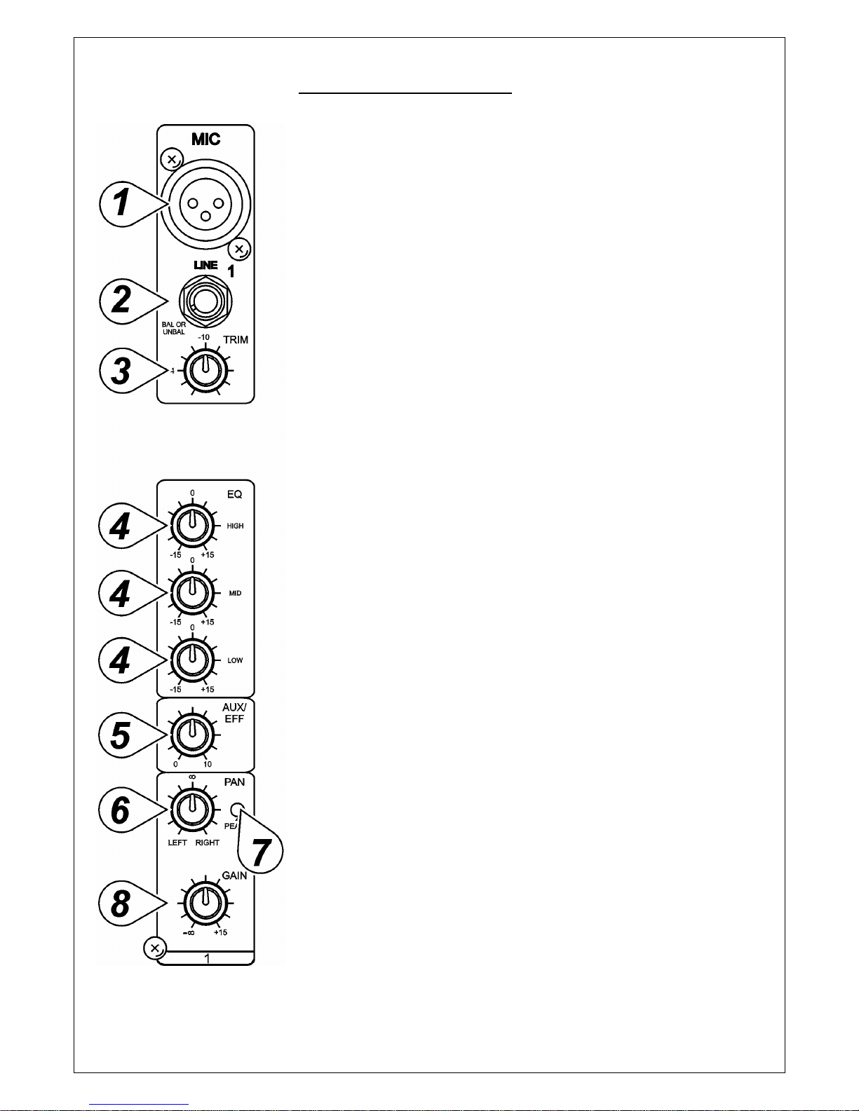
1. MIC INPUT:
Each mono input channel offers a balanced microphone input via the
XLR connector and also features a switchable +48 V phantom power
supply for condenser microphones. The XLR jack is configured for: Pin1
=ground, Pin2 = positive (+), Pin3 = negative (-).
2). LINE IN:
The Line input is designed to accept balanced or unbalanced line level
signals such as those from keyboards, drum machines, or samplers.
There is enough gain available on the line input to accept even lower
level signals, such as those from an unbalanced microphone or guitar
output. If a balanced signal is to be connected to the line input, then a
1/4" TRS (stereo) phone plug should be wired for: Tip = positive (+), Ring
= negative (-), Sleeve = ground.
Note: Only either the MIC or the Line input of a given channel can be
connected at one time. Never connect both simultaneously to the same
channel.
3). TRIM CONTROL:
The TRIM Control adjusts the input sensitivity (channel gain) of the MIC
and line inputs on the mono input channels. This control can be adjusted
to accommodate input signals from a wide variety of sources, from the
high outputs from keyboards or drum machines to the small signal
outputs of microphones. This wide range eliminates the need for
MIC/Line switching. The best balance of S/N and dynamic range will be
achieved if you adjust the TRIM Control on each channel separately so
that the Peak Indicator LED (7) for that channel lights occasionally.
Note: This control should always be turned fully counterclockwise
whenever you connect or disconnect a signal source to one of the inputs.
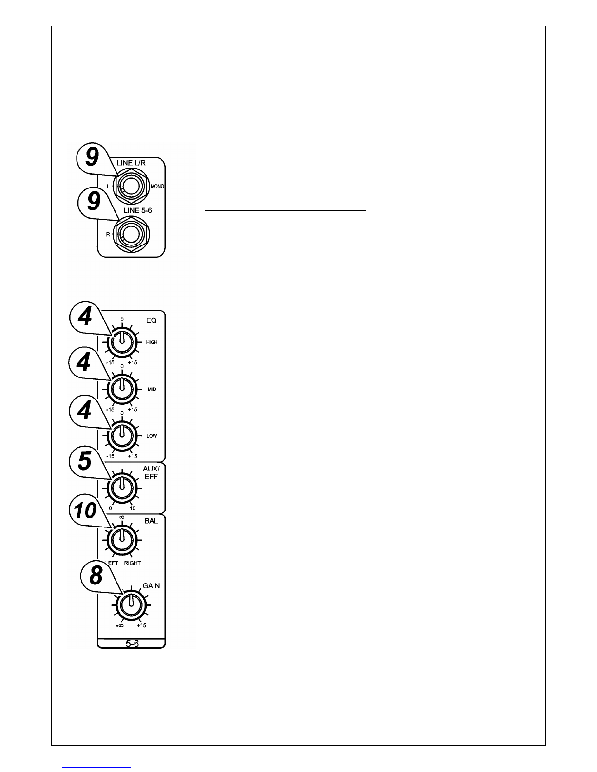
4). EQUALIZER CONTROLS:
All mono input channels are fitted with three-band EQ. The upper (HIGH)
and lower (LOW) shelving controls have their frequencies fixed at 12 kHz
and 80 Hz respectively. The mid range control has a peaking response,
with Q fixed at 2 octaves, frequency at 2.5 KHz. All three bands have up
to 15 dB of cut and boost, with a center detent for "off".
5). AUX/EFF SEND CONTROL:
The AUX/EFF controls are mono and post-EQ and post-fader and the
signal level sent to the AUX/EFFECTS bus will be affected by the
channel fader setting. The AUX configurations is ideal for almost all
monitoring purpose: for example, for a separate stage monitor mix in live
performances or a studio room monitor in recording applications, such as
for a headphone cue system. The EFF controls the adjustment of level
sent by each channel to the internal DSP (Digital Sound Processor).
6). PAN CONTROL:
The Channel Pan positions the output of the channel in the stereo field of
the Master Mix. Its constant-power design ensures there are no level
discrepancies whether a signal is hard-panned, center-stage, or
somewhere in-between.
7). PEAK LED INDICATOR:
The Peak LED illuminates when a channel is going into overload. It
detects the peak level after the EQ and will light at 3 dB before clipping to
warn that the signal is approaching overload. You do not want the Peak
LED to light except very intermittently during a take or a mix. If it does
light persistently, reduce input gain with the TRIM Control (3).