Avery Weigh-Tronix XLR Series Owner's manual

XLR Agricultural Remote Display
XLR-6, XLR-8 AND XLR-12 Models
Installation and Technical Instructions
AWT35-500576
Issue AF

XLR6_8_12_i_en_500576.book
Avery Weigh-Tronix is a trademark of the Illinois Tool Works group of companies whose ultimate parent company is
Illinois Tool Works Inc (“Illinois Tool Works”). Copyright © 2015 Illinois Tool Works. All rights reserved.
No part of this publication may be reproduced by making a facsimile copy, by the making of a copy in three dimensions of a two-dimensional
work and the making of a copy in two dimensions of a three-dimensional work, stored in any medium by electronic means, or transmitted in
any form or by any means, including electronic, mechanical, broadcasting, recording or otherwise without the prior written consent of the
copyright owner, under license, or as permitted by law.
This publication was correct at the time of going to print, however Avery Weigh-Tronix reserves the right to alter without notice the
specification, design, price or conditions of supply of any product or service at any time.

XLR-6, XLR-8 and XLR-12 Installation Instructions 3
Table of Contents
Chapter 1 General Information and Warnings ........................................................................................5
About this Manual ..............................................................................................................5
Text Conventions ........................................................................................................5
Special Messages .......................................................................................................5
Installation ..........................................................................................................................6
Routine Maintenance .........................................................................................................6
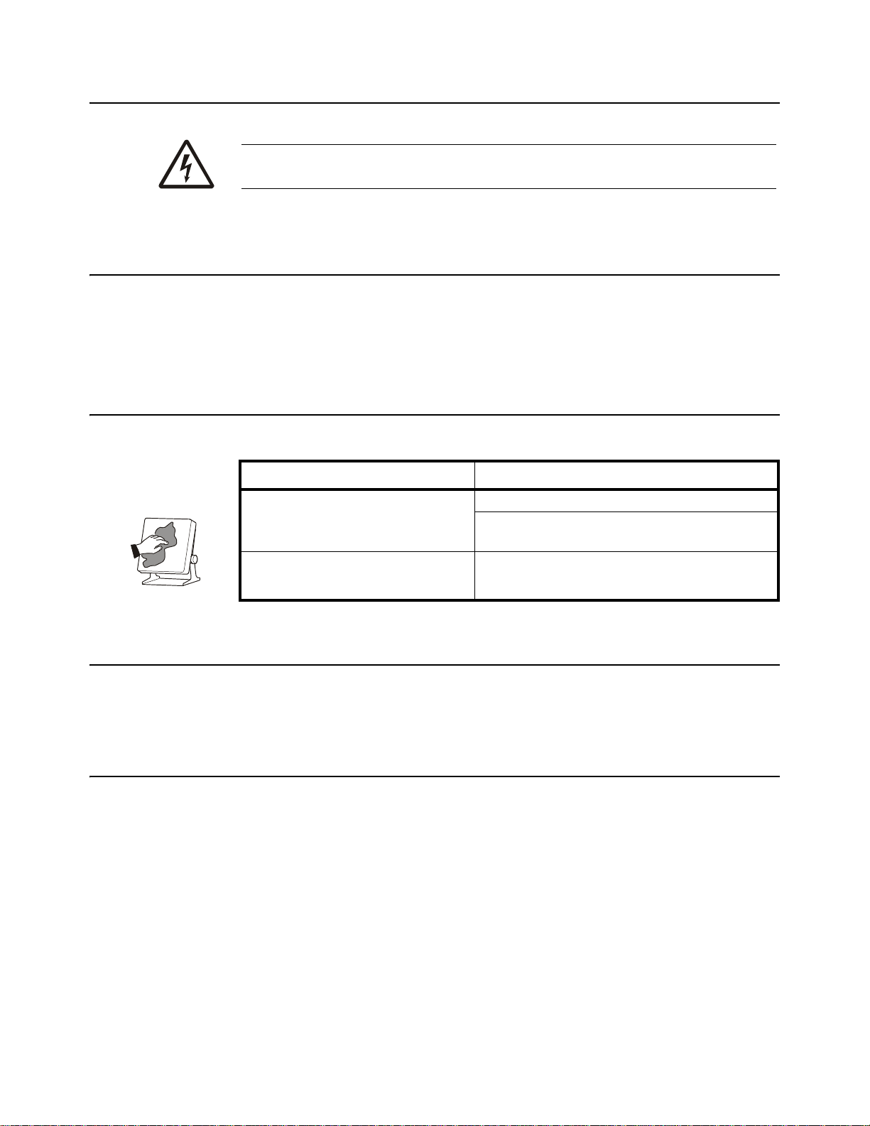
Cleaning the Machine ........................................................................................................6
Training ..............................................................................................................................6
Sharp Objects ....................................................................................................................6
Declaration of Conformity (CE approval) ...........................................................................7
FCC and EMC Declarations of Compliance .......................................................................8
Technical Support ..............................................................................................................8
Chapter 2 Introduction ..............................................................................................................................9
Chapter 3 Installation ..............................................................................................................................10
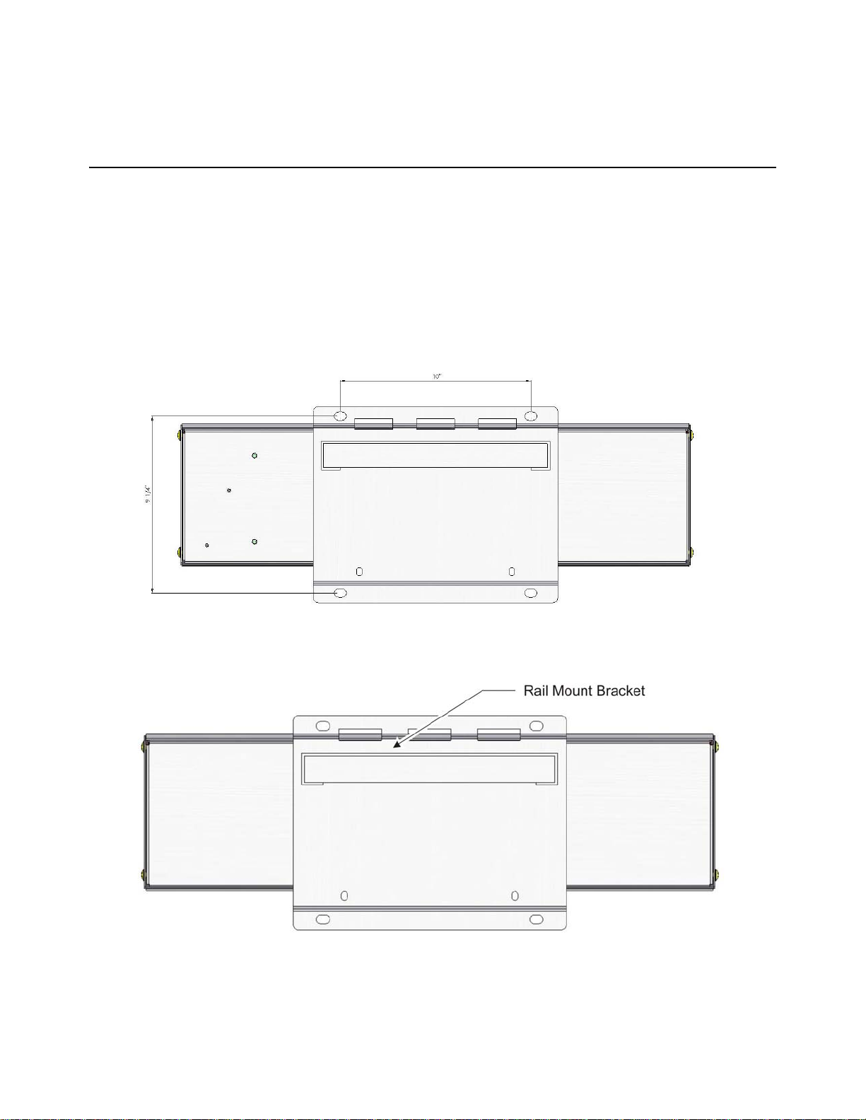
Mounting Brackets ...........................................................................................................10
Adapter Mounting Plate ...................................................................................................11
Stainless Steel Shield ......................................................................................................11
Connecting the Display to Your Equipment .....................................................................12
XLR-8 / XLR-12 Connections ....................................................................................12
XLR-6 Connections ...................................................................................................13
Cables .......................................................................................................................14
Stainless Steel Shield Installation ....................................................................................15
Setup of AWT Ag Indicators for Use With XLR Displays .................................................16
Setup for 640 Series Indicators .................................................................................16
Setup for 1040 and 2040 Series Indicators ...............................................................17
Setup for 2060 Indicators ..........................................................................................17
Setup for 3060 Touch Screen Indicators ...................................................................18
Using two XLR's with 2060 or 3060 Indicators ..........................................................18
Setup for Digi-Star Indicators ....................................................................................19
Chapter 4 Communicating With the Remote Display ...........................................................................20
Computer Control Protocol ..............................................................................................20
Transmit a Weight String ...........................................................................................21
Transmit Status Characters .......................................................................................21
Transmit an Alphanumeric Message / Data String ....................................................21
Control Commands ...................................................................................................22
Sample Data Strings Sent to the Display ..................................................................22
Connector Pin outs ..........................................................................................................23
Chapter 5 Learn a New Transmitter Code (channel 1) .........................................................................24
Chapter 6 Specifications and Parts Lists ..............................................................................................25
Specifications ...................................................................................................................25
Service Parts List .............................................................................................................26
Accessory Parts List ........................................................................................................27

4 XLR-6, XLR-8 and XLR-12 Installation Instructions

XLR-6, XLR-8 and XLR-12 Installation Instructions 5
1 General Information and Warnings
1.1 About this Manual
This manual is dividedinto chapters by the chapter number and the large text at the top
of a page. Subsections are labeled as shown by the 1 and 1.1 headings shown above.
The names of the chapterand the next subsection level appear at the top of alternating
pages of the manual to remind you of where you are in the manual. The manual name
and page numbers appear at the bottom of the pages.
1.1.1 Text Conventions
Key names are shown in bold and reflect the case of the key being described. This
applies to hard keys and onscreen or soft keys.
Displayed messages appear in bold italic type and reflect the case of the displayed
message.
1.1.2 Special Messages
Examples of special messages you will see in this manual are defined below. The
signalwordshave specificmeaningstoalertyoutoadditionalinformation ortherelative
level of hazard.
ELECTRICAL WARNING!
THIS IS AN ELECTRICAL WARNING SYMBOL.
ELECTRICAL WARNINGS MEAN THAT FAILURE TO FOLLOW
SPECIFIC PRACTICES OR PROCEDURES MAY RESULT IN
ELECTROCUTION, ARC BURNS, EXPLOSIONS OR OTHER HAZARDS
THAT MAY CAUSE INJURY OR DEATH.
WARNING!
This is a Warning symbol.
Warnings mean that failure to follow specific practices and procedures may
have major consequences such as injury or death.
CAUTION!
This is a Caution symbol.
Cautions give information about procedures that, if not observed, could result
in damage to equipment or corruption to and loss of data.
NOTE: This is a Note symbol. Notes give additional and important information, hints
and tips that help you to use your product.

6 XLR-6, XLR-8 and XLR-12 Installation Instructions
1.2 Installation
1.3 Routine Maintenance
Always turn off the machine and isolate from the power supply before starting any
routine maintenance to avoid the possibility of electric shock.
Make sure that it is placed securely on a flat and level surface.
1.4 Cleaning the Machine
1.5 Training
Do not attempt to operate or complete any procedure on a machine unless you have
received the appropriate training or read the instruction books.
1.6 Sharp Objects
Do not use sharp objects such as screwdrivers or long fingernails to operate the keys.
DANGER: RISK OF ELECTRICAL SHOCK. NO USER SERVICEABLE
PARTS. REFER TO QUALIFIED SERVICE PERSONNEL FOR SERVICE.
Table 1.1 Cleaning DOs and DON’Ts
DO DO NOT
Wipedowntheoutsideofstandardproducts
withacleancloth,moistenedwithwaterand
a small amount of mild detergent
Attempt to clean the inside of the machine
Use harsh abrasives, solvents, scouring cleaners or
alkaline cleaning solutions
Spray the cloth when using a proprietary
cleaning fluid Spray any liquid directly on to the display windows

XLR-6, XLR-8 and XLR-12 Installation Instructions 7
1.7 Declaration of Conformity (CE approval)
The following XLR-6, XLR-8, and XLR-12 part numbers are CE approved:
Model Part Number
XLR-6 AWT05-508584
XLR-8 AWT05-507376
XLR-12 AWT05-507377

8 XLR-6, XLR-8 and XLR-12 Installation Instructions
1.8 FCC and EMC Declarations of Compliance
United States
Canada
European Countries
1.9 Technical Support
24/7 Customer Support
Avery Weigh-Tronix is dedicated to customer service. We understand downtime is not
an option for AG producers and we're ready to help anytime. The technical support
team for all Avery Weigh-Tronix agri-business scales is available 24 hours a day 7 days
a week.
Ag Technical Support GroupUSA and Canada:
Toll free Phone: (800) 458 - 7062
Outside USA: (507) 238-8261
Tech Support Phone 7:00 am to 5:00 pm CST (800) 458-7062 Ext. 8261
Tech Support Phone/ after hours answering 5:00 pm to 7:00 am CST (800) 458-7062
Service e-mail:
usservice@awtxglobal.com
This equipment has been testedand found to comply with the limits for a Class A digital device, pursuant to Part 15 of the FCCRules.
These limits are designed to provide reasonable protection against harmful interference when the equipment is operated in a
commercial environment. This equipment generates, uses, and can radiate radio frequency energy and, if not installed and used in
accordance with the instruction manual, may cause harmful interference to radio communications. Operation of this equipment in a
residential area is likely to cause harmful interference in which case the user will be required to correct the interference at his own
expense.
This digital apparatus does not exceed the Class A limits for radio noise emissions from digital apparatus set out in the Radio
Interference Regulations of the Canadian Department of Communications.
Le présent appareil numérique n’émet pas de bruits radioélectriques dépassant les limites applicables aux appareils numériques de
la Classe A prescrites dans le Règlement sur le brouillage radioélectrique edicté par le ministère des Communications du Canada.
WARNING: This is a Class A product. In a domestic environment, this product may cause radiointerference inwhichtheusermaybe
required to take adequate measures.

XLR-6, XLR-8 and XLR-12 Installation Instructions 9
2 Introduction
The XLR-6, XLR-8 and XLR-12 remote displays incorporate the most features and
highest performance standards of any agricultural weighing display; making them the
best choice for remote viewing applications.
The XLR series features:
lScrolling 8 or 12 character full Alphanumeric Display.
lUltra wide viewing angles up to 120 degrees.
lMulti interface support including: Avery Weigh-Tronix, Digi-Star and RS-232
Computer interfaces.
lQuad (single for XLR-6) LED digits offering bold and easy to read digits in
direct sunlight.
lDedicated bar graph assists in loading of ingredients.
lLarge G and N annunciator for clear Gross/Net indication.
lBuilt-in standard Radio Clicker for ingredient advancement.
lAuto brightness control dims the display for ease of reading display at night
time (XLR-8 and XLR-12 only).
lEasy to use communication protocol for custom applications.
lSame installation bracket and bolt pattern across all 3 models.
Figure 2.1 XLR-8 and XLR-12 Remote Display
Figure 2.2 XLR-6 Remote Display
NOTE: Remove the protective film on the XLR display. If the film is left on, it will
bake on the display over a period of time and decrease visibility.

10 XLR-6, XLR-8 and XLR-12 Installation Instructions
3 Installation
3.1 Mounting Brackets
The XLR-6, XLR-8 and XLR-12 all have the same mounting bracket options and bolt
pattern.
The display is to be mounted on a solid mounting bracket or surface. The antenna wire
at the bottom right side of the unit should never be cut or pinched during installation.
The XLR remote display is equipped to support equipment that already has a
preexisting rail mount type bracket which is commonly used (refer to section 3.2). The
display can alternatively be mounted using 4 mounting holes shown below. Use
minimum 3/8-16 UNC, 3/4" bolts or equivalent to mount.
Figure 3.1 Standard Mounting Bracket
Figure 3.2 Rail Mount Bracket

XLR-6, XLR-8 and XLR-12 Installation Instructions 11
3.2 Adapter Mounting Plate
When utilizing the Rail Mount bracket (refer to Figure 3.2), there is an adaptermounting
plate (PN AWT20-504460), see Figure 3.3.
Weld or mount the plate to a surface. You can use hose clamps through the slots
marked with a Ain Figure 3.3 to mount it to a pole or post.
There must be a 1/2 space between the plate and the mounting surface to allow room
for the XLR to fit over the mounting plate.
Slip the mounting plate up into the slot on the back of the XLR and use bolts to attach
the XLR to the mounting plate through the bottom, mating holes marked with the letter
Bin Figure 3.3.
The other holes are used to mount various other Avery Weigh-tronix V-mount brackets
and objects.
Figure 3.3 Adaptor Mounting Plate
3.3 Stainless Steel Shield
It is highly recommendedto use the optional Stainless Steel Shield with the XLR series
remote display. The Stainless Steel shield will help keep dust and moisture off of the
display to improve viewing quality.
Part Number Description
AWT20-508532 Protective Stainless Steel Shield XLR-6
AWT20-504832 Protective Stainless Steel Shield XLR-8
AWT20-504833 Protective Stainless Steel Shield for XLR-12

12 XLR-6, XLR-8 and XLR-12 Installation Instructions
3.4 Connecting the Display to Your Equipment
All connections are made at the bottom of the unit using Amphenol 8-pin RS-232
circular connectors. All power and communications goes through a single cable.
3.4.1 XLR-8 / XLR-12 Connections
If you are connecting to Avery Weigh-Tronix or equipment that uses RS-232
communications, then you will be connecting to connector A (8 pin male). If you are
using Digi-Star equipment then connect to connector B (8 pin female). Use only
supplied cable assemblies from the manufacturer.
Figure 3.4 XLR-8 / XLR-12 Connector Configuration
NOTE: The XLR remote never needs to be opened for wiring. There are no switch
settings or internal adjustments required.
CAUTION: Never pressure wash your display as water may be forced through
the connectors causing electrical problems.

XLR-6, XLR-8 and XLR-12 Installation Instructions 13
3.4.2 XLR-6 Connections
If you are connecting to Avery Weigh-Tronix or equipment that uses RS-232
communications, then you will be connecting to connector B (8 pin male). If you are
using Digi-Star equipment then connect to connector A (8 pin female). Use only
supplied cable assemblies from the manufacturer.
Figure 3.5 XLR-6 Connector Configuration

14 XLR-6, XLR-8 and XLR-12 Installation Instructions
3.4.3 Cables
Remote Display Cable with Power Supply
Extension Cable
Digi-Star Remote Display Cables
Part Number Description
AWT25-500473 10 ft / 3.1 m Cable Assembly, Serial RD with power
AWT25-500477 30 ft / 9.2 m Cable Assembly, Serial RD with power
Part Number Description
AWT25-501728 10 ft / 3.1 m extension cable to use with Serial RD cable assembly. This creates a
disconnect point between the indicator in the cab's cable and the remote display's
cable. Very useful when connecting and disconnecting mixer wagon to tractor.
Part Number Description
AWT25-500928 15 ft / 4.6 m Cable Assembly, Interface to Digi-Star
AWT25-500929 30 ft / 9.2 m Cable Assembly, Interface to Digi-Star

XLR-6, XLR-8 and XLR-12 Installation Instructions 15
3.5 Stainless Steel Shield Installation
1. Loosen the screws (two on each side) on both ends of the XLR remote display.
Refer to Figure 3.6 for screw location.
2. Slide the shield in place so that the 4 slots in the shield ends slide over the
screws.
3. Tighten the screws to secure the shield.
Figure 3.6 XLR-6 Protective Shield Installation
Figure 3.7 XLR-8 Protective Shield Installation
without shield with shield
without shield

16 XLR-6, XLR-8 and XLR-12 Installation Instructions
Figure 3.8 XLR-12 Protective Shield Installation
3.6 Setup of AWT Ag Indicators for Use With XLR Displays
Following are the instructions you need to setup an Avery Weigh-Tronix AG indicator
(Models: 640 Series; 640M, 640, 640XL, 1040/2040, 2060 and 3060) for use with an
XLR remote display
3.6.1 Setup for 640 Series Indicators
When using an XLR series remote display with an 640 Series indicator, an RS-232
serial port is required for the communication. Please verify that the 640Series has one
freeserialportbeforecontinuingthroughthesetupsteps.Seetheillustrationoftheport
connection in Figure 3.9.
Figure 3.9 RS-232 port Connection
To configure to communicate with the XLR remote display, use the settings spelled out
in the list below. You may need to reference the 640 Series Service manual or contact
your Avery Weigh-Tronix provider for support. Multiple ports are available on the 640
Series, either Port1 or Port2 supports the XLR.
without shield with shield

XLR-6, XLR-8 and XLR-12 Installation Instructions 17
640 RS-232 Port Settings for XLR Series Remotes
lBaud = 9600
lParity = None
lData = 8
lHand = None
lLayout = Remote
When these settings are used, the XLR remotes will show the same information that is
shown on the display of the 640 Series indicator. The XM60 transmitter is standard in
the XLR remote. When used, it will perform a programmable function for Input 2 in the
640 Series. Changing this function is done in the 640 Series menus and can be
changed by referencing the 640 Series service manual.
3.6.2 Setup for 1040 and 2040 Series Indicators
When using the XLR Series remotes with the 1040 or 2040 indicators, a serial port is
also required. This is the same connection as used in the 640 Series. Please reference
theportconnectionshowninFigure3.9for referencewhenverifyingthe1040/2040has
the required ports.
1040 and 2040 RS-232 Port Settings for XLR Series Remotes
lBaud = 9600
lParity = None
lData = 8
lHand = None
lLayout = RD40RF
All of the messages and weights that are show on the display of the indicator will be
shown on the XLR remote. The XM60 Transmitter is standard in the XLR remote
displays. When used with the 1040, it will advance to the next ingredient in the recipe.
3.6.3 Setup for 2060 Indicators
All 2060 indicators come standardwithtwo Serial ports. Com port 1 is set as the default
remote display port. Com port 1 is always the serial port closest to the Weigh Bar
connectors.
2060 RS-232 Port Settings for XLR Series Remotes
lBaud = 9600
lData (D-Bits) = 8
lParity = None
lS-Bits = 1
lHand (C-trol) = None

18 XLR-6, XLR-8 and XLR-12 Installation Instructions
3.6.4 Setup for 3060 Touch Screen Indicators
RS-232 Com port 2 or Com port 3 can run the XLR. If Feed Foreman is loaded on the
3060, Com port 3 must be used.
3060 touch screen RS-232 Port Settings for XLR Series Remotes
lBaud = 9600
lParity = None
lData = 8
lStop Bits = 1
lHand = None
lPower = On
3.6.5 Using two XLR's with 2060 or 3060 Indicators
In order to run two XLR remotes with the 2060 or 3060, PN AWT05-505541 (XLR
Series Junction box) will be needed. Decide which XLR will have the active XM60
transmitter. In this setup one XLR will simply display weight and a second will also be
synced to a transmitter. Refer to Figure 3.10 for connection details.
Figure 3.10 RS-232 Junction Box Connections
From Indicator From Power Supply
To XLR with Active Transmitter
To XLR with Inactive Transmitter

XLR-6, XLR-8 and XLR-12 Installation Instructions 19
3.6.6 Setup for Digi-Star Indicators
When using the XLR Series remotes with Digi-Star indicators:
1. Connect the XLR to the J-903 Remote port on the EZ-III indicator models (XLR
series is not compatible with EZ-II indicator models.)
Use the AWT Digi-Star interface cable from Avery Weigh-Tronix (PN
AWT25-500928 or AWT25-500929) or the standard cable supplied by
Digi-Star.
2. Follow instructions below based on the Digi-Star model of indicator you are
interfacing to.
Avery Weigh-Tronix XLR series cables for interfacing to Digi-Star
indicators
lAWT25-500928 15 ft / 4.6 m Cable Assembly, Interface to Digi-Star
lAWT25-500929 30 ft / 9.2 m Cable Assembly, Interface to Digi-Star
EZ3 Indicators with full alpha and alphanumeric keypad (GT460, NT460,
EZ4600, EZ3600V, EZ3400VL, and EZ3400)
1. Enter 234 and press Select.
2. Press Select until EZ3MUX is displayed.
3. Press Enter.
EZ3 Indicators with alphanumeric keypad (EZ2500V, EZ2400V, EZ400,
and GT400)
1. Press Net/Gross first and then press On and hold them both down at the same
time until scrolling message "Press Select or Net…." appears.
2. Press Select until Menu2 appears and press On.
3. Press On until RMDisp appears then the current selection appears (EZ3MUX
or EZ2).
4. Press Select until EZ3MUX appears then press On.
5. Cycle power by turning the indicator off then back on or press On until you get
into weighing mode.

20 XLR-6, XLR-8 and XLR-12 Installation Instructions
4 Communicating With the Remote Display
The XLR display automatically selects which type of communications protocol is being
used. When connecting to Avery Weigh-Tronix or Digi-Star equipment, the display will
automatically translate the display information correctly. No configuring of the display
is required. There are no adjustable settings for this display.
When transmitting weights to the display the annunciator character located on the left
hand side of the display will clearly display a G for gross weight or N for net weight. For
Digi-Star equipment the annunciator character will also flash L when loading
ingredients.
Whenthedisplayisdisplayingalphanumerictextmessages,theannunciator character
is not displayed.
The bar graph located across the bottom indicates how close you are to target when
loading product. This is displayed as % of target weight.
4.1 Computer Control Protocol
If the display information is sent from alternate equipment using RS-232, then the
equipment’s baud rate must be set to 9600 no parity and 1 stop bit (9600 N81).The
display will attempt to analyze and display the weight information automatically.
Custom applications may communicate to the display using a simple command
protocol that allows applications to make full use of all of the displays features.
All commands sent to the display must terminate with a CR character ASCII 13.
NOTE: When connecting to non-Avery Weigh-Tronix equipment, 12V must be applied
to the remote power pin 7 on the connector.
This manual suits for next models
3
Table of contents
Other Avery Weigh-Tronix Monitor manuals