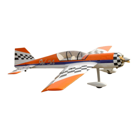
Aviation Models 37.5% Yak 54 User manual

1
Aviation Models
37.5% YAK 54 A
s
sembly Manual
For assistance contact :
Aviation
Models
25022 104th Ave
SE, Suite E
Kent, WA 98030
Product Information:
1
-
253
-
332
-
0786
Ordering Hotline:
1
-
866
-
877
-
8621
Copyright © 2005 by Aviation Models, Inc. All rights reserved.
Second edition rev. 5.12.28

2
WarrantyInformation:
Aviation Models, Inc. guarantees this kit to be free of defects in both material and
workmanship at the time of purchase. This warranty does not cover any comp
o-
nents damaged by use or modification. In no case shall Aviation Models, Inc. l
i-
ability exceed t
he original cost of the pu
r
chased kit
.
Further, Aviation Models, Inc, reserves the right to change or modify this warranty
without notice. In that Aviation Models has no control over final assembly or m
a-
terials used in final a
s
sembly, no liability shall
be assumed or accepted for any
damage resulting from the use by user of the final user assembled product. By the
act of using the user assembled product, the user accepts all resulting l
i
ability.
If the buyer is not prepared to accept the liability assoc
iated with the use of this
product, the buyer is advised to return this kit immediately in new and unused co
n-
dition to the place of pu
r
chase.
While this kit has been flight tested to exceed normal use, if the plane will be used
for extremely high stress flying such as racing or extreme aerobatics the modeler is
responsible for ta
k
ing steps to reinforce the high stress points. If you do not feel
confident to do this, seek advice from e
x
periencedmodelers.
Read through this manual before starting constru
c-
tion. It contains important warnings and instructions
concerning the assembly and use of this model.

3
Warning. This is not a toy. If not properly con
trolled it
can cause injury or death and prop
erty damage.
Included Hardware: Aluminum spinner, fueltank,aircraftgradealuminum
wing
-
tube, aluminum main gear, rubber wheels, tail wheel bracket, alum
i-
num servo arms, aluminum stab tube for r
e
movable stab, control horns,
hinges, wheel pants, SAE bolts and nuts, much more.
Specifications:
Wingspan:
121in
FuselageLength:
108.5 in
Wing Area:
2854 sq. in
Engine:
150cc
Flying Weight:
37.5 lbs
Thank you for buying a Aviation Models airplane. We are proud to produce
one of the best designed, built and covered almost ready to fly
(ARF)
model airplanes available on today's market. If you have any que
s
tions
about your new plane, assembly manual or hardware, feel free to call our
Aviation Models guarantees this kit to be free of defects at the time of pu
r-
chase. This warranty does not cover any components damaged by use or
modification. In no case shall Aviation Models' liability exceed the
original cost of the purchased kit.
Since Aviation Models has no control over final assembly, no liability shall
be assumed or accepted for any damage resulting from the use by user of
the final user assembled product.
Warning. This is not a toy. If not properly controlled it can
cause i
n
jury or death and property damage.

4
Table of Contents
Page
Subject
5
Open and inspect ev
e
rything
5
Using this manual
6
GeneralAcknowledgments
7
Installing Servos in the Wing
9
Hinge the control su
r
faces
11
Pushrods
13 Install the main landing gear & Wheel Pants
16
Install the elevator servos
17
RudderInstallation
19
Tailwheel Assembly
20 Mount the rudder servo and linkage
20
Mount the horizontal stabilizers
21
Mount the engine
22
Throttle servo i
n
stallation
23 Prepare and Mount Cowl
23
Mount the wings
23
Mount the hatch and canopy
24
C
heck and adjust balance
24
Co
n
trol throws
25
Final Caution

5
37.5% Yak 54 Assembly Manual
Step 1. Open and inspect everything
This section should be fairly self e
x
planatory.
In the large box you should have a fuselage with hatch., wing tube and dual stab
tub
es, the elevator/stab asse
m
blies, the rudder, cowl, wheel pants, canopy, and a
package with the landing gear, tail wheel bracket and mi
s
cellaneous nuts and bolts.
Use some acetone on a rag to clean the glue off the tubes. Under all of this is a
falsefloor
, and under that you will find the wings with aile
r
ons attached. The
hinges are installed in the elevators and ailerons, but they are not glued, you have
to do that. The hinges for the rudder are in the hardware pack. We have had good
luck with Pro
-
bond Ul
timate and Gorilla glue, both of which are glues that expand
as they dry cure and fill the voids in the hinges and their sockets.
Check everything for shipping damage and/or manufacturing defects. If there is a
problem, r
e
port it to us NOW
, not after you
start building the plane.
Read the quick start guide at the end of this manual first. It has hel
p
ful hints
and any errata corrections that may be available.
Before proceeding to any assembly, now is a good time to go over the whole plane
and fix any cosmetic flaws. Some cosmetic flaws are to be expected, this fact is r
e-
flected in the price.
Using This Manual
When you start a construction section, it is a good idea to first read that entire se
c-
tion before cu
t
ting or drilling or gluing. For example, if you are about to begin the
section called “Mount the Hatch and Canopy”, then read that entire section b
e
fore
doing anything else. Toward the end of that section, there is an option to paint
frame line on the inside of the canopy. If you’ve already glued it on, it will be im-
possible. Reading the entire section will give you a good feel of where you are
headed and any options available.

6
Knownissuesandimprovements
There are a few areas where, at this unassembled stage, you can improve the final
resul
ts of your assembly project. There are many items that cannot be addressed on
the a
s
sembly line due to cost and possibly because not every improvement would
be welcomed by every builder. Here are a few items that have come up over time.
Go over the coveri
ng with a heat gun or iron
. The covering tends to get loose
over time and with changes in temperature and humidity. It may have come out of
the box with wri
n
kles, I can assure you it did not go into the box that way.
Clean out the hinge holes.
Without rem
oving any wood, use a very sharp X
-
acto
knife and r
e
move any covering that may have been pushed into the hinge holes. It
is very important that the glue sticks to the wood and not to the covering.
Lightweight landing gear and wing tube.
In the 37.5% YAK w
e have tried to
provide as much flexibility as possible with regard to engine choice. It is som
e-
times difficult to be all things to all people. In any case, we have provided very
strong landing gear and wing tubes, which are sui
t
able for any type of engin
e and
flying but add some weight to the finished plane. Some pilots chose to order ca
r-
bon f
i
ber landing gear and/or wing tubes. This can save several ounces of weight.
Hardening holes. The fuselage sides on this plane are made of balsa which in ce
r-
tain
areas is doubled by lite
-
ply. Using wood screws in balsa is diff
i
cult because
balsa is very soft. It’s a good idea whenever you drill a hole that must accept a
wood screw to put a drop of thin CA into the hole and then if necessary re
-
drill the
hole. The
CA will wick into the wood and harden it, adding strength in that area.

7
Installing Servos in Wings and Hinging Ailerons
Locate the servo bay holes and
cut the covering back. Use your
covering iron and tack the cove
r-
ing around the edges.
Install the servo with four servo
screws.
3. Locate the aluminum
arm pr
o-
vided in your hardware package.
After installing your servo into the
servo bays, apply power to the
servo and make sure they are
centered. Check that your
trim and sub
-
trim in your Tran
s-
mitter are centered. Install the
aluminum servo arm so it is
at
90
-
degree angle to the servo
case.

8
Using a 2mm drill bit, drill four
holes through the servo wheel.
(You may also want to purchase
some metal after
-
market servo
wheels or arms for added
strength. If after
-
market arms
are used, they should be 1
-
1/2"
l
ong).
Once the four holes are drilled,
install the metal arm to the
wheel using four 2x10mm bolts.
Use a clamp to help hold the
control surface in a center
position. Use something like
a scrap piece of balsa or lite
-
ply to prevent the clap from
damaging your finish.

9
Hinging
is a very simple matter. We
recommend that you hinge all the
co
n
trol surfaces in two steps
allowing the glue to dry between
steps.
Before you start gluing anything,
test fit each control surface
-
Aileron
to wing, el
e
vator to stabilizer, rudder
to fin/f
use, with the hinges in place.
Make sure the hinges go in the
holes smoothly and that there is
ample room for the hinge “knuckle” so there is no large gap between su
r-
faces. The hinge lines are be
v
eled. The point of the bevel should be at the
center of the
hinge pin, this assures that the hinges are aligned and ce
n-
tered on the hinge line. (see below)
With the servo and arm i
n
stalled,
you can now start to measure the
length of your pushrods.
You can use whatever d
e
vice you
like for a control arm. You can
drill through the moving surface
and thread a bolt through, use a
control ho
rn, or a surface mount
arm. But whatever you choose,
try to keep the pivot point of the
clevis over the hinge point.

10
Once you are certain that they all go together smoothly, take one su
r
face
and remove the hinges. If you have a needle oiler, place 1 or 2 drops of oi
l
into the hinge and work it back and forth. It’s also a good idea to put some
lite oil (like WD40) on a rag, and to wipe the edges of the hinging surfaces
with this rag. The oily residue will keep spilled glue from sticking to the u
l-
tracote covering. Then wipe off any excess oil from the surface. Glue the
hinges into the holes securely using the glue you prefer. I have had good
success with Pro
-
bond polyur
e
thane (not the pro
-
bond yellow furniture
glue) because when drying it foams up slightly and fills the gaps between
the hinge and the mounting hole. Pacer Hinge glue works great for the
same reason.
Make sure the bent hinge is able to go perpendicular to the edge (see pi
c-
ture).
When the glue is dry, do the same
thing with the mating surface,
glue
the hinge legs into the holes
provided. Keep the surfaces as close
together as possible to minimize
gaps. When completed it’s a good
idea to seal the hinge gaps by ironing
a piece of Ultracote covering material into the groove between the su
r-
faces.

11
To make the rudder removable, it is possible to remove the hinge pin from
each hinge (grind off the
recessed end and push the pivot out) and one or
two pieces of wire as the pivot on all the hinges. Use the largest wire that
will fit through the hinge holes. Then to r
e
move the rudder you just remove
the wire, but be sure the wire can’t fall out in flight
.
Repeat this on both elev
a-
tors and both ailerons. For
the rudder you may wish to
wait until later to do the final
installation of the rudd
er, it
makes it easier to handle
the ai
r
plane.
With control surface in center
posi
tion and servo centered,
measure the length of the pus
h-
rod and mark. Make sure you a
l-
low ¼” of threads on each end to
screw into the ball link and co
n-
trol horn.
You can now cut your pushrod to
length and install.

12
Remove the servo arm from
the servo and
thread the ball
link onto the pushrod.
Repeat this process for each
of your servos
–
on each co
n-
trol su
r
face.
Once you have all the servos mounted, it is a good idea to use a
matchbox or other equalizing device, so that there is no binding in the
servos. If such a device is not used, extreme care must be taken to m
e-
chanically match and adjust servo and linkage geometry to avoid bin
d-
ing, or servos fighting each other. If this step is overlooked or not pe
r-
formed with care, loss of control of model is very
likely.
This goes for all control surfaces with multiple servos.

13
Installing the Landing Gear
Locate the landing gear pr
o-
vided with the plane.
Use the four 1/4x20 bolts pr
o-
vided to mount the gear to the
gear plate. Back the bolt from
the inside with the four lock nuts
provided
as well.
The bolts come through the
canister tunnel. You will need a
wrench to hold them in place
while tightening the bolts.

14
Align the wheel pant and tape it
into place. Then hold the wheel
pant and drill the center hole
through the lan
d
ing gear.
Take a smaller drill bit and drill
through the holes in the landing
gear. Then place blind nuts on
the i
n
side of the wheel pant.
When the wheel pant is fi
n
ished
it should look like this.

15
Insert the axel through the wheel
pant with the wheel inside
the
pant and tighten the nut on the
inside of the wheel pant. Use the
provided wheel collars to s
e
cure
the wheel pant.
Use the provided bolts to s
e
cure
the wheel pant into place. Tighten
bolts into the previously inserted
blind nuts for a secure fit.

16
Installing Servos in Horizontal
Stabilizer
M
ount the servo in the servo bay
and install the arm onto the
servo.
You can now start to measure the
length of your pushrods.
Drilling holes for the control
horns:
Follow the same procedure as for
the ailerons to mount your Elev
a-
tor control horns
.
Hinging Elevators:
Follow the same procedure as for
the Ailerons to hinge your Elev
a-
tors.

17
After your control rod is properly
installed into your control su
r-
face, connect the rod to both the
ball link and the clevis. Make
sure the arm is 90 d
e
grees to
the horn.
Stab servo, servo arm, and el
e-
vator control horn. The same
steps apply to the elevator as
with the ailerons. Make sure
each servo is in center position
with the control horn centered.
HingingRudder:
The rudder is removable, and
hinges need t
o be glued to the
rudder first, then to the vertical
stab. Dry fit rudder to vertical
stab. Mark on rudder and on
stab where hinges are located.
Remove rudder from stab, and
remove hinges from rudder. Use
pr
e
ferred hinging glue and pour a
line of glue ove
r each pre
-
slotted
hinging hole in the rudder, allo
w-
ing the glue to pen
e
trate deep into
the groove.

18
Place hinges into the groove and
probe them in and out se
v
eral
times to ensure that the glue has
thoroughly covered the hinge.
Before glue dries, insert
hinge
rod through hole in top of rudder,
and guide it through the hinges,
attaching the non
-
gluedhinge
half, and lining the hinges up on a
straight line. Repeat gluing pro
c-
ess for the vertical stab. Then
push the two surfaces t
o
gether to
complete the hing
ing.
Rudder control horn:
Drill through the hard point in the
rudder and mount your control
horn. Make sure that the control
horn is low enough to clear your
full down elevator travel.
Insert linkage onto control su
r
face
and make sure the linkage i
s
evenlycentered.

19
Tail Wheel Installation:
Install your preferred tail wheel
to the hard wood at the rear
section of the fuselage. Here
is an example of our install
a-
tion.
Here is another picture of the
tail wheel installation.
Rudder Cable:
Take
a straight edge and
mark where the rudder cable
will touch the fuse side.
You are looking for a straight
shot all the way up to your
rudder se
r
vos. Make sure you
have clearance between the
cable and your elevator at full
travel.

20
Mount your servos in the
pr
o-
vided slots. Pre
-
drill the servo
mounting screws and fasten
servos.
Rudder servo installation:
The torque of your servos and
your flying style will be dete
r-
mi
n
ing factors of how many se
r-
vos you will need. If you decide
to run more than two, simply
e
xtend the mount and run them
inline, ganging them together.
Make sure that the distance
from each cable at the mounting
point is the same di
s
tance as
the rudder control horn. This will
allow a slack free pull
-
pull sy
s-
tem.
Mounting the Horizontal Stab
i-
liz
ers.
Insert the provided bolts into the
fuse through the stab and s
e-
cure the stabilizer in place.
Table of contents
Other Aviation Models Toy manuals
Popular Toy manuals by other brands

Mega Bloks
Mega Bloks Xtreme Sports Skate Flip manual

Eduard
Eduard BRASSIN MiG-29 exhaust nozzles manual

Atlas O
Atlas O GP-7 owner's manual

Lionel
Lionel Wild West Set owner's manual

Eduard
Eduard Sunderland Mk.III exterior quick start guide

advanced scale models
advanced scale models Sukhoi SU-26M Assembly instructions