Aviation Models 30% YAK 54 User manual

1
Aviation Models
30% YAK 54 A
s
sembly Manual
For assistance contact :
Aviation
Models
25022 104th Ave SE, Suite E
Kent, WA 98030
ProductInformation:
1
-
253
-
332
-
0786
OrderingHotline:
1
-
866
-
877
-
8621
Copyright © 2005 by Aviation Models, Inc. All rights reserved.
Second edition rev. 5.12.12

2
WarrantyInformation:
Aviation Models, Inc. guarantees this kit to be free of defects in both material and
workmanship at the time of purchase. This warranty do
es not cover any comp
o-
nents damaged by use or modification. In no case shall Aviation Models, Inc. l
i-
ability exceed the orig
i
nal cost of the purchased kit
.
Further, Aviation Models, Inc, r
e
serves the right to change or modify this warranty
without notice
. In that Aviation Models has no control over final assembly or m
a-
terials used in final assembly, no liability shall be assumed or accepted for any
damage resulting from the use by user of the final user assembled product. By the
act of using the user assembled product, the user accepts all resulting l
i
ability.
If the buyer is not prepared to accept the liability associated with the use of this
product, the buyer is advised to return this kit immediately in new and unused co
n-
dition to the place of pu
r
chas
e.
While this kit has been flight tested to exceed normal use, if the plane will be used
for extremely high stress flying such as racing or extreme aeroba
t
ics the modeler is
responsible for ta
k
ing steps to reinforce the high stress points. If you do not
feel
confident to do this, seek advice from experienced modelers.
Read through this manual before starting constru
c-
tion. It contains important warnings and i
n
structions
concerning the assembly and use of this model.
The pictures in this manual may be of
airplanes with different covering schemes.
The planes pictured were of identical construction. Only the color schemes were
different.

3
Warning. This is not a toy. If not properly con
trolled it
can cause injury or death and prop
erty damage.
Included Hardware: Aluminum spinner, fuel tank, aircraft grade aluminum
wing
-
tube, aluminum main gear, rubber wheels, tail wheel bracket, alum
i-
num servo arms, aluminum stab tube for r
e
movable stab, control horns,
hinges, wheel pants, SAE bolts and nuts, much more.
Specifications:
Wingspan:
87"
Length:
75.5"
Flying Weight:
16lbs
Wing
Area:
1411sq.in.
Engine Size:
50cc
CANISTER
READY, COWL RING MOUNT, PRE
-
HINGE
-
SLOTTED SU
R-
FACES,PUSH
-
RODS AND CONTROL LINKAGES INCLUDED, 5” POLISHED
SPINNER
INCLUDED FUEL TANK, WHEELS, LANDING GEAR, MOUNTING
HARWARE, NUTS, BOLTS AND MORE
–
ALL INCLUDED
FULL
PARTS
SUPPORT
IN
STOCK
Additional equipment r
e
quired:
Computer Radio with at least 8 cha
n
nels
2 Elevator servos minimum 100 oz/in. of torque each
2 a
ileron servos, total torque required not less than 120 oz./in. per wing.
Rudder servo(s) at least 180 oz./in.
Throttle servo
Radio operated engine kill switch or servo operated choke strongly su
g
gested
Single or dual radio battery packs at least 1650 mAh
total
Switch[es]for receiver batteries
Miscellaneousservoextensions.
Flexing in linkage can and will cause flutter of the control surfaces which will
destroy the airplane in just a few seconds. Metal gear se
r
vos are required.

4
Table of Contents
Pag
e
Subject
5 Open and inspect ev
e
rything
6 Mount the engine
10 Hinge the control su
r
faces
12 Mount the hatch and canopy
13 Mount the horizontal stabilizers
13 Install the control horns
14 Install the elevator & aileron servos
16 Throttle and (optional) choke servo installation.
17 Install the landing gear
18 Mount the rudder servo and linkage
18 Install a fuel tank and fuel system
19 Prepare and Mount Cowl
20 Mount the wings
20 Final Checks
21 Check and adjust ba
l
ance
21 Control throws

5
30% Yak 54 Assembly Manual
Step 1. Open and inspect everything
This section should be fairly self e
x
planatory.
In the large box you should have a f
u
selage with hatch., wing tube and dual stab
tubes, the elevator/stab asse
m
blies, the rudder, cowl, wheel pants, cano
py, and a
package with the landing gear, tail wheel bracket and mi
s
cellaneous nuts and bolts.
Use some acetone on a rag to clean the glue off the tubes. Under all of this is a
false floor, and under that you will find the wings with ailerons attached. The
hinges are installed in the elevators and ailerons, but they are not glued, you have
to do that. The hinges for the rudder are in the hardware pack. We have had good
luck with Pro
-
bond Ultimate and Gorilla glue, both of which are glues that expand
as they
dry cure and fill the voids in the hinges and their sockets.
Check everything for shipping da
m
age and/or manufacturing defects. If there is a
problem, report it to us NOW, not after you start building the plane.
Read the quick start guide at the end of this manual first. It has hel
p
ful hints
and any errata corrections that may be available.
Before proceeding to any assembly, now is a good time to go over the whole plane
and fix any cosmetic flaws. Some cosmetic flaws are to be expected, this fact is r
e-
f
lected in the price.
Using This Manual
When you start a construction section, it is a good idea to first read that entire se
c-
tion before cutting or drilling or glueing. For example, if you are about to begin
the section called “Mount the Hatch and Canopy”, then read that entire section b
e-
fore doing anything else. Toward the end of that section, there is an option to paint
frame line on the inside of the canopy. If you’ve already glued it on, it will be im-
possible. Reading the entire section will give
you a good feel of where you are
headed and any options available.

6
Knownissuesandimprovements
There are a few areas where, at this unassembled stage, you can improve the final
results of your assembly pr
o
ject. There are many items that cannot be ad
dressed on
the a
s
sembly line due to cost and possibly because not every improvement would
be welcomed by every builder. Here are a few items that have come up over time.
Go over the covering with a heat gun or iron
. The covering tends to get loose
over tim
e and with changes in temperature and humidity. It may have come out of
the box with wri
n
kles, I can assure you it did not go into the box that way.
Clean out the hinge holes. Without removing any wood, use a very sharp X
-
acto
knife and remove any covering that may have been pushed into the hinge holes. It
is very important that the glue sticks to the wood and not to the covering.
Lightweight landing gear and wing tube. In the 30% YAK we have tried to pr
o-
vide as much flexibility as po
s
sible with regard to e
ngine choice. It is sometimes
difficult to be all things to all people. In any case, we have provided very strong
landing gear and wing tubes, which are suitable for any type of engine and flying
but add some weight to the finished plane. Some pilots chose to order carbon f
i
ber
landing gear and/or wing tubes. This can save several ounces of weight.
Hardening holes. The fuselage sides on this plane are made of balsa which in ce
r-
tain areas is doubled by lite
-
ply. Using wood screws in balsa is diff
i
cult be
cause
balsa is very soft. It’s a good idea whenever you drill a hole that must accept a
wood screw to put a drop of thin CA into the hole and then if necessary re
-
drill the
hole. The CA will wick into the wood and harden it, adding strength in that area.
Engine mounting
PLEASE READ THE INSTRU
C
TIONS FOR STEP 2 COMPLETELY BEFORE
CUTTINGANYTHING!
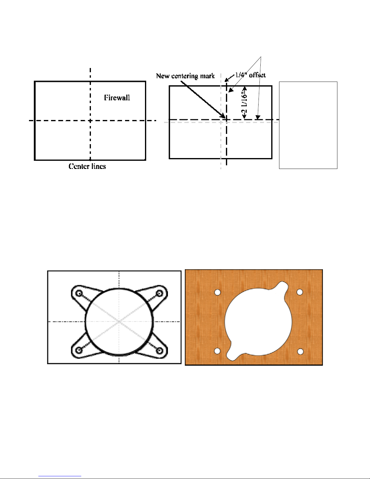
The first thing to do, before anything else goes in the fuselage, is to get the engine
mounted and aligned with the cowl. This can be a little tricky, so take you
r time.
This is perhaps the most difficult part of building this kit, so once you get this
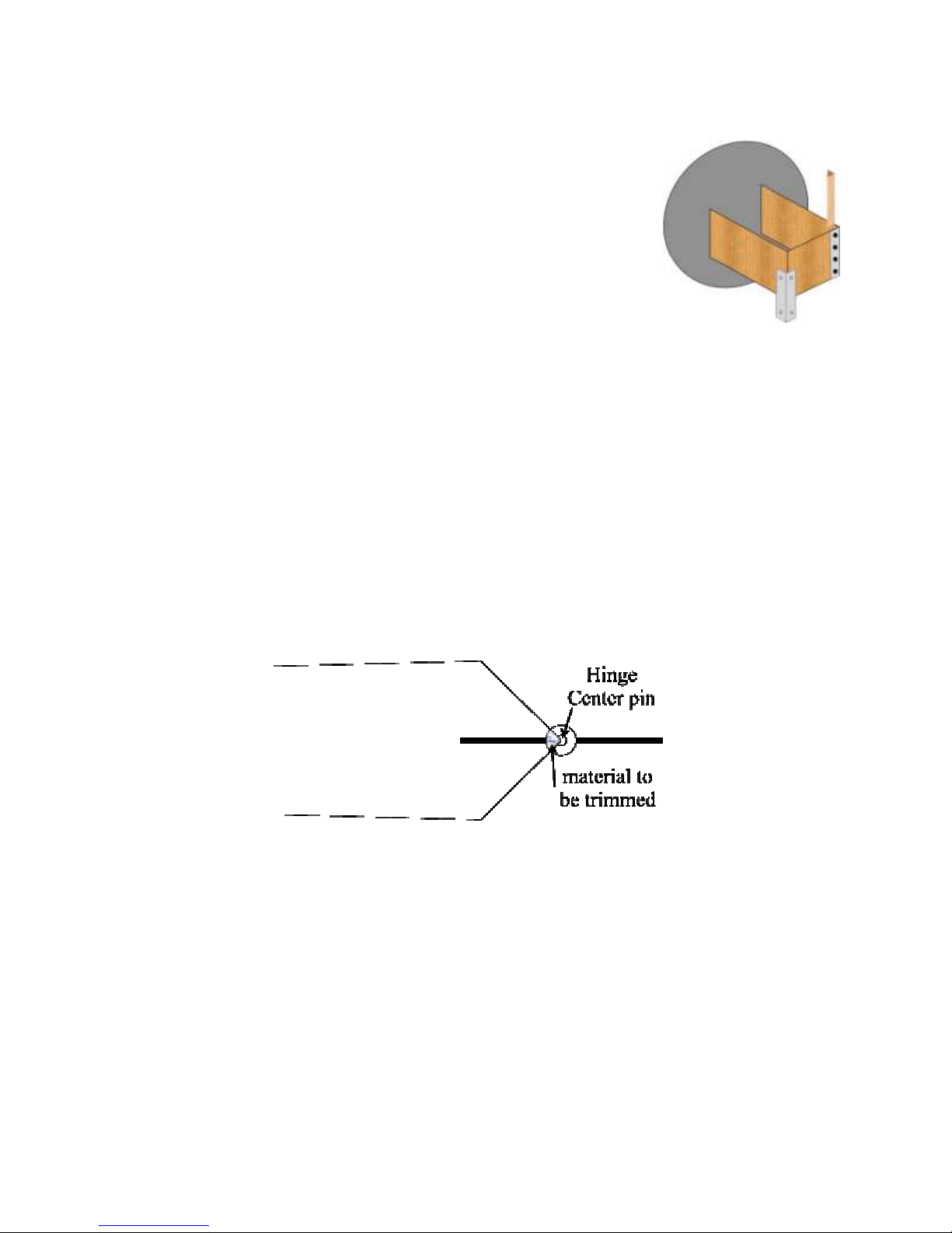
right, you’re on your way to having a great plane. Do this first before you hinge
the ru
d
der.
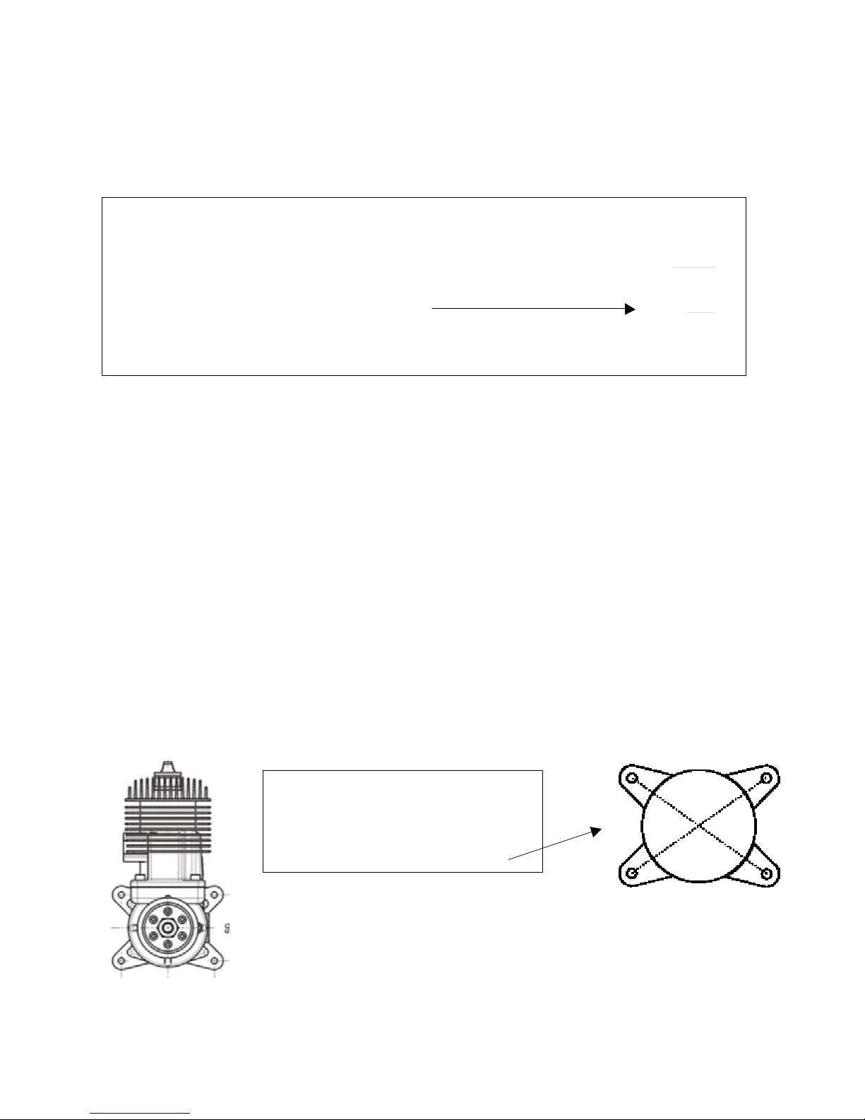
Note that the firewall already has a proper amount of right thrust bu
ilt in, do not
use any other offsets. When you shim the engine out from the firewall use shims of
equal thickness on all 4 corners so that you do not introduce any other thrust a
n-
gles.
This plane is designed around an e
n
gine of 3 to 4 1/2 pounds. If you pl
an to use a
heavier engine (some people plan to use 70
-
75cc, even though that is way ove
r-
powered and overweight) it’s a good idea to double the firewall. I have flown this

7
plane with a 60cc(4.0 lbs) on the front, and it had an insane amount of zip. With
HiTec 5945’s on the elevators, pull
-
pull ru
d
der, and the 4.0 lb. engine on the front,
the CG came out right on the factory recommendation without any batteries inside.
Sim
ply place one battery right in front of the wing tube, and one right behind and
your
CG will be very close. This is just a guide, each plane should be checked i
n-
dividually.
We will prepare our engine box in four steps:
(1)
Calculating the engine box length
(2)
Cutting the engine box
(3)
Marking and preparing our firewall
(4)
Glue and re
-
enforce firew
all
(1)
Calculating the engine box length
{Engine Cowl length (plus) ¼” prop clearance} (minus) engine length = e
n
gineboxlength
To determine your engine cowl length, place the cowl on a flat counter and place a
straight edge across the top. With a rule, measure from the flat counter to the bo
t-
tom of the straight edge.(see figure 1) Write this number down
–
it is your cowl
length(CL). NOTE: The back mounting plate of your cowl is r
e
cessed ¼” from
the e
p
oxy
-
glass edge. Use a ¼” shim under your yardstick so that our zero point
is the back of the pl
y
wood mounting plate.
Measure your engine from the rear of the mounting plate to the surface that the
rear of the prop will rest. (see figure 2) This is your e
n
gine length (EL)
Figure1
Figure2

8
Now, let’s calculate the proper engine box length for your setup.
Cowllength (minus) enginelength=engineboxlength
If you measure the sides of your e
n
gine box, you will see that they are d
ifferent
lengths. This is because some right thrust is built in. Add the 2 measurements and
divide by 2 to get the length at the center.
EXAMPLE: one side measures 6 5/8”(starboard) and the other 6 7/8”(port). Our
average uncut engine box length would be (6 5/8” + 6 7/8”) / 2 = 6 3/4” If we use
the e
x
ample above and wanted our final engine box length to be 6 1/16”, then 6
3/4”(avg. original length)
–
6 1/16”(final length) = 11/16”. I would have to cut
11/16” from each of the e
n
gine box sides. By cutting both sides the same amount,
we do not change our thrust a
n
gle.
Now, let’s mark and prepare our fir
e
wall for engine mounting before we glue it in
place.
First, remove your carburetor and trace your engine mounting plate.
EXAMPLE:
CL = 11 3/4” EL = 5 15/16” so,
11.75
-
5.94
engine box =
5.81
now let’s add ¼” so our prop will
_
.25
ha
ve a little clearance from the cowl
6.06
We would cut our engine box to be 6 1/16” long
After you trace it, cut it out and
then draw diagonals from hole
to hole. When you are done, it
should look similar to this:

9
Nextmark
your firewall with center lines. Label the firewall “Top” and “front“
with a pencil. Now measure & mark the last 2 lines as shown.
We are now ready to mark and drill our firewall for our engine. Take the engine
mount pattern you made in t
he last step and place it over the firewall so that the
center marks of the engine pattern line up with the new centering mark on the fir
e-
wall. Rotate until vertical. Use an ice pick or an awl to push though the center of
each of the 4 engine mounting holes. Make sure you make the hole big enough to
find later. When done, drill the firewall through each awl mark with the appropr
i-
ate size bit for your engine mounting bolts. (10
-
32 hardened, socket head bolts and
blind nuts will do nicely) Also use a hole saw or jig saw to cut out the center until
yourcarburetor passes througheasily.
We are now ready to epoxy the fir
e
wall into the engine box. BE SURE TO PUT
THE TOP AT THE TOP AND THE FRONT TO THE FRONT
–
as labeled in the
previous step. Wipe away excess epoxy. A large blob in the wrong place will pr
e-
vent the proper fit of the triangular stock in the next step. After your wipe away
the excess, a little rubbing alcohol on a paper towel will finish the job nicely.
The¼”offset isto
counte
r
act t
he
right thrust. This
willbringthe prop
shaft back to the
centerof thecowl
asite
x
its.

10
After you glue the fire
wall to the engine box sides,
reinforce it with 1/2” tr
i
angle stock on the inside of the
firewall
-
above and below mid
-
plate. Drill out the center
hole so that the carburetor passes easily through the
firewall. If you want it to be super strong, bolt 2 sma
ll
pieces of aluminum a
n
gle to the front (see diagram).
Hinging
Like I said, the rest is very easy.
Hinging is a very simple matter. We recommend that you hinge all the control su
r-
faces in two steps allowing the glue to dry between steps.
Before you
start gluing anything, test fit each control surface. Aileron to wing, el
e-
vator to stabilizer, rudder to fin/fuse, with the hinges in place. Make sure the
hinges go in the holes smoothly and that there is ample room for the hinge
“knuckle” so there is no
large gap between surfaces. The hinge lines are beveled.
The point of the bevel should be at the center of the hinge pin, this assures that the
hinges are aligned and ce
n
tered on the hinge line.
Once you are certain that they all go together smo
othly, take one surface and r
e-
move the hinges. If you have a needle oiler, place 1 or 2 drops of oil into the hinge
and work it back and forth. It’s also a good idea to put some lite oil (like WD40)
on a rag, and to wipe the edges of the hinging surfaces with this rag. The oily res
i-
due will keep spilled glue from stic
k
ing to the ultracote covering. Then wipe off
any excess oil from the su
r
face. Glue the hinges into the holes securely using the
glue you prefer. I have had good success with Pro
-
bond polyu
rethane (not the pro
-
bond yellow furniture glue) because when dr
y
ing it foams up slightly and fills the
gaps b
e
tween the hinge and the mounting hole. Pacer Hinge glue works great for
the same reason.

11
Make sure the bent hinge is able to go perpendicular to
the edge (see pi
c
ture).
When the glue is dry, do the same thing with the mating surface, glue the hinge
legs into the holes provided. Keep the surfaces as close together as possible to
minimize gaps. When completed it’s a good idea to seal the hinge gaps by ironing
a piece of U
l
tracoat covering material into the groove between the surfaces.
Repeat this on both elevators and both ailerons. For the rudder you may wish to
wait until later to do the final i
n
stallation of the rudder, it makes it easi
er to handle
the ai
r
plane.
To make the rudder removable, it is possible to remove the hinge pin from each
hinge (grind off the recessed end and push the pivot out) and one or two piece of
wire as the pivot on all the hinges. Use the largest wire that wil
l fit through the
hinge holes. Then to r
e
move the rudder you just remove the wire, but be sure the
wire can’t fall out in flight. I have used a very small wheel collar to retain the
hinge wire.

12
Mounting the Hatch & Canopy
The hatch mounts
to the fuselage by
two tabs on each side that are a
t-
tached at the rear of the hatch. They
are already built into the hatch and
should have 6
-
32 blind nuts mounted
in them. Set the hatch in place and
check to see that the 6
-
32 bolts
(supplied) thread ea
s
ily into the blind
nuts. You may have slightly enlarge
the holes in the fuse if the blind nuts
don’t line up perfectly. Check also to
see if the 2 dowels are protruding out
of the front at least ¼”
–
and that they
are glued in s
e
curely. Once you are
sat
isfied, remove the hatch. We will now attach the canopy to the hatch.
The full scale YAK has frame lines in the canopy. These should be molded into
your clear canopy. If you wish to paint these in or dye your canopy, now is the
time. You can paint them on the inside if you do not dye. With a Covering Iron,
touch
-
up any wrinkles in the Ultra
-
Cote covering where your ca
n
opy will sit.
Make sure the Ultra
-
Cote is stuck well to the balsa in this area. Once the ca
n
opy is
glued, you will not be able to get into this area. Carefully trim the canopy to fit the
hatch. Leave a small lip in the front, it makes the attachment more secure. Trial fit
it se
v
eral times until you are happy with it. Remember, you can always trim more
off but it’s hard to put back o
n. Attach the ca
n
opy with whatever is your favorite
method. Some people use tape, some glue the ca
n
opy down, some use small
screws. This is up to you. If you use small screws add some hard wood such as
1/16” ply to back up the balsa wood of the hatch. I
like E
-
6000 clear glue found at
your local hobby store. If you use it, run a small bead(1/8” diameter) all the way
around the canopy. Hol
d
ing the canopy by the edges, open it slightly and carefully
lower it into place. Use a few pieces of electrical tape to hold it in place overnight.
Don’t worry about any E
-
6000 that may squeeze out. It is actually ea
s
ier to clean
after it hardens. You can trim it carefully with a sharp X
-
acto and roll it off.

13
Install horizontal stab
i
lizer
Use a sharp hobby knife to carefully trim the covering around the holes in the fuse
for the stab tube and the bolt holes on each side. Slide the aluminum
tube(supplied) through the fuse, and slide the stab
i
lizers onto the tubes from each
side. Make sure that both stabs are snu
g against fuse. Using the 6
-
32allen
bolts(supplied), attach the stabs to the fuse.
Install the Control Horns
Mount the provided control horns to each
control surface on the hard points. Try and
get the control horn base as close to the
leading edge of the control su
r
face. This will
provide the proper geometry and allow the
control surface to move both dire
c
tions
equally. For the elevators, place each horn
1” from the fuse, and the exact same di
s-
tance from the hinge line. Otherwise, the
geometry will be different and
it will be diff
i-
cult to adjust the throw amount to be equal
in both directions. (See di
a
grams below)
Stab
Elev
a
tor

14
Elevator Servo Insta
l
lation
Aileron Servo Installation
Find the open servo bay on the left
and right side of the fuselage in the
tail. Remove covering.
Attacha
servo extension to the servo cord
long eno
ugh to reach the receiver,
and tie this servo connector t
o-
gether with de
n
tal floss or whatever
you prefer. Slide the exte
n
sion
through the servo hole and fish the
end through the fuse with a piece
of wire with a hook or whatever you
want to use. There is
a channel
cut in the bo
t
tom each former. If
you run the e
x
tensionsthrough
these holes it keeps the wires from
flopping around in flight. Servos
should be s
e
cured with all screws.
Cut back the covering and i
n
stall
the rudder and elev
a
tor servos
onto th
e pre
-
installedhardwood
mounting rails.
Find the aileron servo bay in each
wing. Cut back the covering. There
is a string attached inside . Pull it
loose and use it to pull the servo
wire through the channel in the
wing. Once again, add a servo
wire
extension if necessary and
secure. Install the servo onto the
pre
-
installed hard wood rails.
Mount the aileron control horn pe
r-
pendicular to the servo arm in the
pre
-
installed hardwood moun
t
ing
base.
Hard Point
90*

15
A servo mounting box is supplied. G
lue
it together using thick CA. Mount it in
the front compartment. Space it from
the sidewall to accommodate your e
n-
gine. This was installed with a 60cc
engine and spaced with 2 pieces of ¼”
X ½” balsa. Make sure the servo arm
clears the tank and any other obstacles
when it moves. The piece of plastic
pushrod just helps absorb a little of the
engine vibration.
If you wish to use a servo to control
your choke, you can cut the mid
-
plate
appropriately to drop in your servo.
Use 2 pieces of 1/16” ply a
s doublers
for the screws to have some meat .
The pros is that it give an added
measure of safety (extra kill method)
and is co
n
venient. The cons is that it
adds a little extra weight and may
slightly effect performance. Also a
little more battery drain
. A mechan
i-
cal choke is another option and is pi
c-
tured.
The bellcrank and hardware for a
mechanical choke hookup is not pr
o-
vided but can be purchased inexpe
n-
sively at your local hobby shop.
Position the bell
-
crank so that the
pushrod exits the fuse abou
t ¾” in
front of the landing gear notch. If you
use a canister muffler, this entire
linkage will have to be repositioned.

16
Main Landin
g Gear Installation
Tail Wheel Install
a
tion
Using the four 8
-
32 X 1” long bolts
provided, and four 8
-
32 locknuts pr
o-
vided. Mount the landing gear to the
main gear plate as sh
own in the pi
c-
ture. The gear sweep slightly bac
k-
ward.
Use a 2.5 mm or 3/32” drill bit to drill 3
moun
t
ing holes.
Put a few drops of thin CA into the
holes to harden the wood.
Let it dry
.

17
Rudder Control Horn Setup
Use three, 3x4mm self
-
tapping
screws to secure the tail w
heel
bracket to the holes drilled in the
last step.
Using two 8
-
32x3/4” allen bolts,
run them through the gear and
through the holes in the pant.
Take a small square piece of
plywood and glue it to the inside
of the pant. Now take two 8
-
32
blind nuts and tighten the allen
bolts. Once the blind nuts are
tight add a small amount of glue
to the blind nuts to hold them in
place. Glue another piece of ply
to the opposite side of the pant to
catch the axel. This will pr
o
vide
some additional s
tr
ength.
Mount the rudder control horn to the
rudder the same way as the elevators
and ailerons. Make sure that with full
up elevator you have plenty of clea
r-
ance between the control horn and
the elevator. If you do not have the
proper clearance the elevato
r will hit
your pull
-
pull wire. Once your control
horn is mounted you can now install
the pull
-
pull wire. Make sure that the
wire goes straight to the rudder servo
in the fuse.

18
Trim the cut
-
out in the center of
the ru
d
der servo tray to fit your
rudder servo.
Glue the stiffeners to the bottom
of the ru
d
der servo tray.
The tray will fit approximately in
thisp
o
sition. You may want to
delay this process until you have
everything i
n
stalled & then move
this forward or aft in order to a
d-
just CG.
Most will be able to glue it in this
position and adjust CG with ba
t-
tery plac
e
ment.
Cut 2 pieces of ¼” X ½” balsa stick 72
mm long each. Epoxy one on
each
side of the fuse. These will fit under
the tray & between the stif
f
eners.
When the epoxy cures, trial fit the tray
by dropping it onto the 2 rails. If ev
e-
r
y
thing looks good, apply epoxy to the
top of the rails and position the tray.

19
Engine cooling and clearance
Run the pull
-
pull wires down the
fuselage, and make sure the c
a-
bles are not
rubbing on anythin
g
.
Attach the large aluminum servo
arm securely to an existing servo
wheel and attach cables with
hardwareprovided.
Cut out the cowl in the required spots
so you have plenty of clea
r
ance
around the muffler and cyli
n
der.
Also open
up the box on the bottom of
the cowl in o
r
der to cool the engine
during flight. If you do not provide
enough exit for the air, the e
n
ginewill
overheat.
The installation of the tank (supplied)
and fuel lines is very straightforward.
Pl
ace a piece of foam under the tank
to prevent fuel foaming and strap it
with tie
-
wraps or Velcro.

20
Wing Mounting
Final Checks
Take a few minutes to re
-
check each serv
o to make sure all screws are in place and snug.
If you use metal gear servos(a good idea), place one drop of thread locker on the screws
that hold the arms on the servos. Re
-
check all control horns, and all linkage for slop or
looseness. This would gre
atly increase the chance of flutter and could destroy your ai
r-
plane. This is a 3D/Aerobatic airplane with large surfaces. Be careful to keep everything
tight and control your speed when flying.
Put on your prop and spinner. Put in all radio and batteri
es. Mount all switches & attach
all wiring. A
s
semble the airplane, we will now check the CG.
Once the cowl is ready to mount,
slide it onto the fuselage and attach
using6
-
32 bolts and washers
pr
o-
vided. Two screws go through the
fir
e
wall into the cowl ring
–
two go
through the ring into the firewall.
Blind
-
nuts are already installed to r
e-
ceive them.
Mark the root rib of each wing 6 ½”
from the leading edge. Transfer the
mark to the undersi
de of the wing. We
will use this measurement in a bit to
check our Center of Gravity (CG).
Use the supplied nylon mounting bolts
to attach the wing onto the f
u
selage.
Make sure that the wing bolts are in
place and snug before each flight to
prevent the w
ing from coming off du
r-
ing flight.
Table of contents
Other Aviation Models Toy manuals
Popular Toy manuals by other brands

Mega Bloks
Mega Bloks Xtreme Sports Skate Flip manual

Eduard
Eduard BRASSIN MiG-29 exhaust nozzles manual

Atlas O
Atlas O GP-7 owner's manual

Lionel
Lionel Wild West Set owner's manual

Eduard
Eduard Sunderland Mk.III exterior quick start guide

advanced scale models
advanced scale models Sukhoi SU-26M Assembly instructions