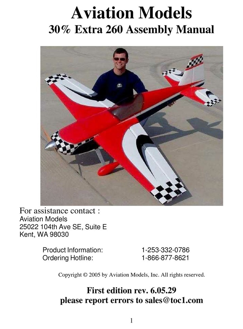
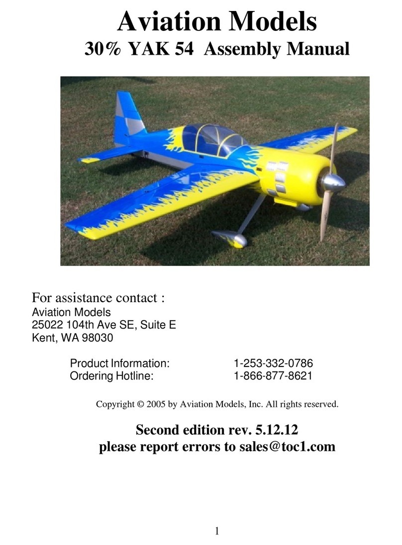
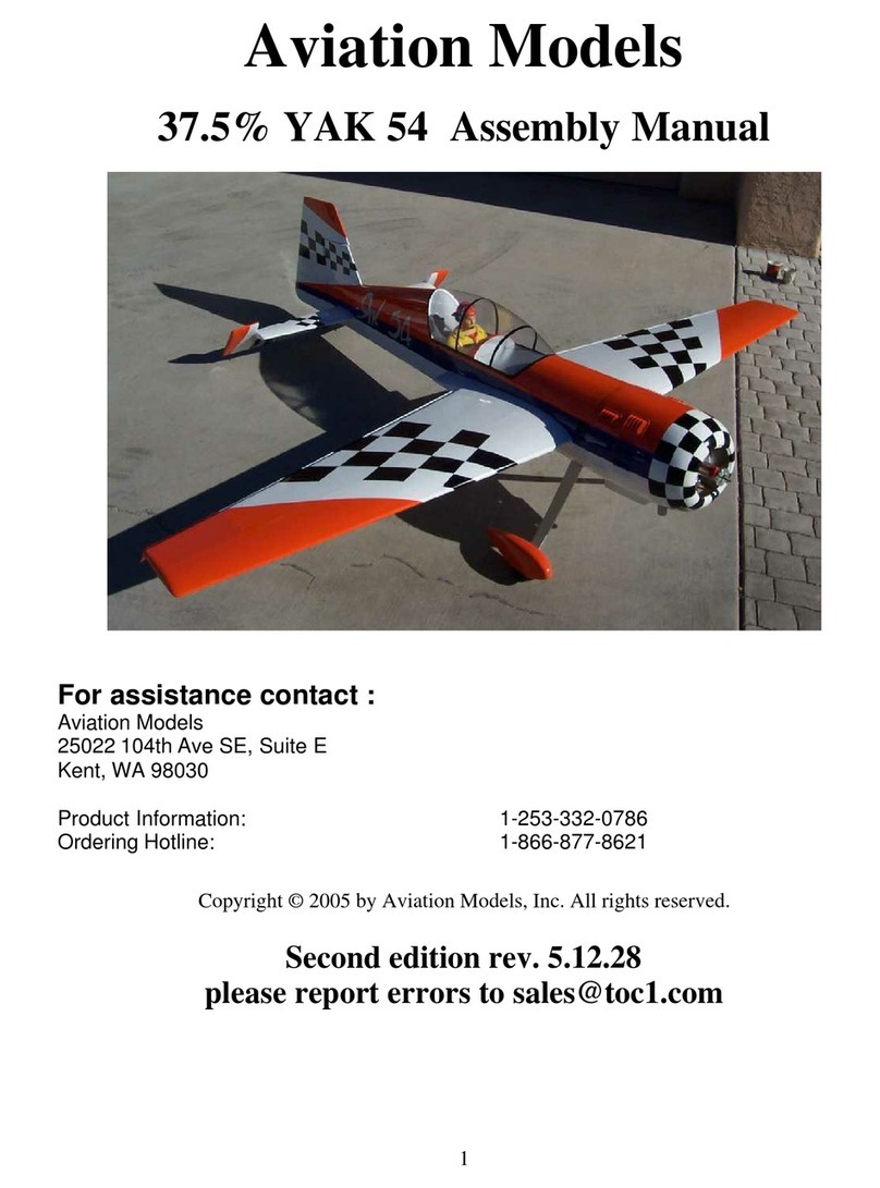
Aviation Models YAK 54 User manual

2
WarrantyInformation:
Aviation Models, Inc. guarantees this kit to be free of defects in both material and
workmanship at the time
of purchase. This warranty does not cover any
comp
o
nents damaged by use or modification. In no case shall Aviation Models,
Inc. l
i
ability exceed the orig
i
nal cost of the purchased kit
.
Further, Aviation Models, Inc, r
e
serves the right to change or modify this warranty
without notice. In that Aviation Models has no control over final assembly or
ma
terials used in final assembly, no liability shall be assumed or accepted for any
damage resulting from the use by user of the final user assembled product. B
y
the act of using the user assembled product, the user accepts all resulting l
i
ability.
If the buyer is not prepared to accept the liability associated with the use of this
product, the buyer is advised to return this kit immediately in new and unused
co
n
dition to the place of pu
r
chase.
While this kit has been flight tested to exceed normal use, if the plane will be used
for extremely high stress flying such as racing or extreme aeroba
t
ics the modeler is
responsible for ta
k
ing steps to reinforce the high
stress points. If you do not feel
confident to do this, seek advice from experienced modelers.
Read through this manual before starting constru
c
tion.
It contains important warnings and i
n
structions
concerning the assembly and use of this model.
The pic
tures in this manual may be of airplanes with different covering schemes.
The planes pictured were of identical construction. Only the color schemes were
different.

3
Warning. This is not a toy. If not properly con
trolled it
can cause injury or
death and pro
p
erty damage.
Operation of this model should at all times be in
compliancewithAcademyofModelAeronauticssafety
rules.
CANISTER READY, COWL RING MOUNT,PRE-HINGE-SLOTTED SURFACES,
PUSH-RODS AND CONTROL LINKAGES, 5” POLISHED
ALUMINUMSPI
NNER,
FUEL TANK, AIRCRAFT
GRADE ALUMINUM WING
-
TUBE, ALUMINUM MAIN
GEAR,
RUBBER WHEELS, ALUM
I
NUM SERVO ARM, ALUMI
NUM STAB TUBE FOR
RE
MOVABLE STAB, HINGES
, WHEEL PANTS,
MOUNTING HARDWARE, NUTS,
BOLTS AND MORE –ALL INCLUDED
.
Specifications:
Wingspan:
95 in.
Wing Area:
1
74
2
sq.
in
.
Fuselage length:
89.3 in
.
Total flying weight:
19.5 lbs
Engines:
75
-
80CC
Flexing in linkage can and will cause flutter of the control surfaces which will
destroy the airplane in just a few seconds. Metal gear se
r
vos are required.

4
Table of Contents
Page
Subject
5 Open and inspect everything
6 Using This Manual
7
Hinging
8 Mount Aileron Servos
9 Aileron Linkage
10 Install the Landing Gear
12
E
ngine Mounting
16 Engine Pictures
17 Hinging the Rudder
18
Rudder Servo/Pull
-
Pull System
21 Elevator Servos and Linkage
23 Wheel Pants
26
Fuel Tank /Throttle/Choke
27
Prepare and Mount Cowl
27
Canopy
28
Mount the wings
29 Component Layout
29
Check and Adjust balance
30 ControlThrows

5
Step 1. Open and inspect everything
This section should be fairly self e
x
planatory.
In the large box you should have a f
u
selage with hatch., wing tube and dual stab
tubes, the elevator/stab asse
m
b
lies, the rudder, cowl, wheel pants, canopy, and a
package with the landing gear, tail wheel bracket and mi
s
cellaneous nuts and bolts.
Use some acetone on a rag to clean the glue off the tubes. Under all of this is a
false floor, and under that you will fi
nd the wings with ailerons attached. The
hinges are installed in the elevators and ailerons, but they are not glued, you have
to do that.
The hinges for the rudder are in the hardware pack. We have had good
luck with Pro
-
bond Ultimate and Gorilla glue, both of which are glues that expand
as they dry cure and fill the voids in the hinges and their sockets.
Check everything for shipping da
m
age and/or manufacturing defects. If there is a
problem, report it to us NOW, not after you start building the plane.
Before proceeding to any assembly, now is a good time to go over the whole plane
and fix any cosmetic flaws. Some cosmetic flaws are to be expected, this fact is
re
flected in the price.

6
Using This Manual
When you start a construction section, it is a go
od idea to first read that entire
se
c
tion before cutting or drilling or gluing. For example, if you are about to begin
the section called “Mount the Hatch and Canopy”, then read that entire section
b
e
fore doing anything else. Toward the end of that secti
on, there is an option to
paint frame line on the inside of the canopy. If you’ve already glued it on, it will
be i
m
possible. Reading the entire section will give you a good feel of where you
are headed and any options available.
Known issues and improv
ements
There are a few areas where, at this unassembled stage, you can improve the
final results of your assembly pr
o
ject. There are many items that cannot be
addressed on the a
s
sembly line due to cost and possibly because not every
improvement would be welcomed by every builder. Here are a few items that
have come up over time.
Go over the covering with a heat gun or iron
. The covering tends to get
loose over time and with changes in temperature and humidity. It may have
come out of the box with wrinkles, I can assure you it did not go into the box
that way.
Clean out the hinge holes.
Without removing any wood, use a very sharp
X
-
acto knife and remove any covering that may have been pushed into the
hinge holes. It is very important that the glue sticks to the wood and not to the
covering.
Lightweight landing gear and wing tube. In the 33% YAK we have tried to
pr
o
vide as much flexibility as po
s
sible with regard to engine choice. It is
sometimes difficult to be all things to all people. In any case, we hav
e
provided very strong landing gear and wing tubes, which are suitable for any
type of engine and flying but add some weight to the finished plane. Some
pilots chose to order carbon f
i
ber landing gear and/or wing tubes. This can
save several ounces of weight.
Hardeningholes.
The fuselage sides on this plane are made of balsa which
in ce
r
tain areas is doubled by lite
-
ply. Using wood screws in balsa is
diff
i
cult because balsa is very soft. It’s a good idea whenever you drill a hole
that must accept a wood screw to put a drop of thin CA into the hole and then
if necessary re
-
drill the hole. The CA will wick into the wood and harden it,
adding strength in that area.

7
Hinging
Hinging is a very simple matter. We recommend that you hinge all the control su
r
fa
ces in
two steps allowing the glue to dry between steps.
Before you start gluing anything, test fit each control surface. Aileron to wing, el
e
vator to
stabilizer, rudder to
fin/fuse, with the
hinges in place. Make
sure the hinges go in
the holes smooth
ly
and that there is
ample room for the
hinge “knuckle” so
there is no large gap
between surfaces.
The hinge lines are beveled. The point of the bevel should be at the center of the hinge
pin, this assures that the hinges are aligned and ce
n
tered on the hinge line.
Once you are certain that they all go together
smoothly, take one surface and r
e
move the hinges. If
you have a needle oiler, place 1 or 2 drops of oil into
the hinge and work it back and forth. It’s also a good
idea to put some lite oil (lik
e WD40) on a rag, and to
wipe the edges of the hinging
surfaces with this rag. The oily
res
i
due will keep spilled glue
fromstic
k
ing to the ultracote
covering. Then wipe off any
excess oil from the su
r
face.
Glue the hinges into the holes
securelyusing the glue you
prefer. I have had good
success with Pacer Hinge
glue because when dr
y
ing it
foams up slightly and fills the gaps b
e
tween the hinge and the mounting hole
Make sure the bent hinge is able to go perpendicular to the
edge (see pic
ture).

8
When
the glue is dry, do the same thing with the mating surface, glue the hinge legs into
the holes provided. Keep the surfaces as close together as possible to minimize gaps.
Wipe off excess glue and clean up carefully. When the glue is completely dry, it’
s a
good idea to seal the hinge gaps by ironing a piece of U
l
tracote covering material into the
groove between the surfaces.
Repeat this process on all control surfaces. For the rudder you may wish to wait until
later to do the final i
n
stallation of the rudder, it makes it easier to handle the ai
r
plane.
To make the rudder removable, it is possible to remove the hinge pin from each hinge
(grind off the recessed end and push the pivot out) and one or two piece of wire as the
pivot on all the hinges. Use the largest wire that will fit through the hinge holes. Then to
r
e
move the rudder you just remove the wire, but be sure the wire can’t fall out in flight. I
have used a very small wheel collar to retain the hinge wire.
Mount the Aileron Servos
1.
Use appropriate servo extensions so
that servo wires will be long enough to go
from their mounting position to the
interior of the fuselage. Then remove
the covering from the servo mounting
holes. Use
the string provided to pull
the servo wire through the interior
channel in the wing until it exits at the
wing root.
2.
Mount the servos in place using
proper servo mounting screws as
pictured below.
Temporarily connect the servos, receiver,
switch, a
nd battery pack. Turn on
Transmitter and receiver switch. Place
all transmitter trims at the center position.
All servos should centered.

9
3.
Mount the arm to the servo wheel.
4.
Mark location of the control horn.
The linkage should be perpendicul
arto
hinge line and the control horn should
be mounted to the hard
-
point built into
the aileron.
Take care when positioning control
horns. The pivot point of the clevis
should be as much as is possible directly
over the hinge point.

10
Landing Gear
Locate the hard
-
points. Drill and
mount the control horns using the
hardware provided.
Tighten the bolts provided. Do not
over
-
tighten. You could crush
thewood
or strip the plastic horn backplate.
Repeat this process for each control
surface. Try to keep all control horn
locations symmetric. For example, if the
left elevator horn is 3 7/16” from the
fuselage, then the right elevator horn
should also b
e 3 7/16” from the fuse. Etc.
We want to keep the geometry identical if
possible
--
same angles, same distances.
Bolts and locking nuts are provided to
mount the main landing g
ear.
The main gear are constructed to have
a slight sweep to them. Position the
gear so that they sweep slightly
forward.

11
You will need a wrench to back up the
nuts so that they don’t spin as you
tighten the bolts.
Install blind nuts and install Tailwheel
with
bolts provided. Attach a steering wire
as shown below.
Position the Tailwheel so that
the swivel point is directly
over the hinge point of the
rudder. Mark and drill
mounting holes.

12
Engine mounting
PLEASE READ THE INSTRU
C
TIONS FOR STEP 2 COMPLETELY BEFORE
CUTTING ANYTHING!
The first thing to do, before anything else goes in the fuselage, is to get the engine
mounted and aligned with the cowl. This can be a little tricky, so take your time.
This is perhaps the most difficult part of building this kit, so once you get this right,
you’re on your way to having a great plane.
Do this first before you hinge the
ru
d
der.
Note that the firewall already has a proper amount of right thrust built in, do not
use any other offsets. If you shim the engine out from the firewall use shims of
equal thickness on all 4 corners so that you
do not introduce any other thrust
an
gles.
This plane is designed around an e
n
gine of 5 to 5 1/2 pounds. If you plan to use a
heavier engine (some people plan to use 90
-
100cc, even though that is way
over
powered and overweight) it’s a good idea to double th
e firewall.
We will prepare our engine box in four steps:
(1)
Calculating the engine box length
(2)
Cutting the engine box if necessary
(3)
Marking and preparing our firewall
(4)
Glue and re
-
enforce firewall
Tighten tail wheel carefully.

13
(1)
Calculating the engine box length
{Engine Cowl length
(plus) ½”
-
3/4” prop clearance (PC} (minus) engine length =
en
gineboxlength
To determine your engine cowl length, place the cowl on a flat counter and place a
straight edge across the top. With a rule, measure from the flat counter to the
bo
t
tom of
the straight edge.(see figure 1) Write this number down
–
it is your
cowl length(CL). NOTE: The back mounting plate of your cowl is r
e
cessed
¼” from the e
p
oxy
-
glass edge. Use a ¼” shim under your yardstick so that our
zero point is the back of the pl
y
wood mounting plate.
Measure your engine from the rear of the mounting plate to the surface that the
rear of the prop will rest. (see figure 2) This is your e
n
gine length (EL)
Figure1
Figure 2
Now, le
t’s calculate the proper engine box length for your setup.
{
CL
-
EL} + PC = engine box length
EXAMPLE:
CL = 13” EL = 6” so,
13”
-
6”
7”
now let’s add ¼” to ¾” (personal preference) so our prop will
.5”
have a little clearance from the cowl
7.5”
We would cut our engine box to be 7.5” long. In this case, our engine box is only
71/8”
long. So we won’t cut it but rather use four 3/8” standoffs from the firewall.

14
If you measure the sides of your e
n
gine box, you will see that they are different lengths.
This is because some right thrust is built in. Add the 2 measurements and divide by 2 to
get the length at the center.
EXAMPLE: one side measures 7”(starboard) and the other 7 1/4”(port). Our average uncut
engine box length would be (7” + 7 1/4”) / 2 = 7 1/8” If we use the e
x
ample above and
wanted our final
engine box length to be 7.5”, then 7 1/8”(avg. original length)
–
7.5”(final
length) =
-
3/8”. A negative number indicates that our engine box is too short so we would use
four 3/8” standoffs to bring it to the needed length. If it had been a positive
number,we
would cut the engine box by that amount. By cutting both sides the same amount, we do not
change our thrust an
gle.
Now, let’s mark and prepare our fir
e
wall for engine mounting before we glue it in place.
First, remove your carburetor and trace your engine mounting plate.
Next mark your firewall with center lines. Label the firewall “Top” and “front“ with a
pencil. Now measure & mark the last 2 lines as shown.
The measurement labeled X will vary, depending on your engine, but you want the shaft
After you trace it, cut it out and then draw
diagonals from hole to hole. When you
are done, it should look similar to this:
The ¼” offset is to
counte
r
act the ri
ght
thrust. This will
bring the prop shaft
back to the center of
thecowlasite
x
its.

15
of your engine to be aligned with the center line of the wing.
We are now ready to mark and drill our firewall for our engine. Take the engine mount
pattern you made in the last step and place it over the firewall so that the center marks of
the engine pattern line up with the new centering mark on the fir
e
wall. Rotate until
vertical. Use an ice pick or an awl to push though the center of each of the 4 engine
mounting holes. Make sure you make the hole big enough to f
ind later. When done,
drill the firewall through each awl mark with the appropr
i
ate size bit for your engine
mounting bolts. (10
-
32 hardened, socket head bolts and blind nuts will do nicely) If
you use short standoffs or none at all, your firewall will
need to be cut out for the
carburetor. Use a hole saw or jig saw to cut out the center until your carburetor passes
through easily.
We are now ready to epoxy the fir
e
wall into the engine box. BE SURE TO PUT THE
TOP AT THE TOP AND THE FRONT TO THE FRONT
–
as labeled in the previous step.
Wipe away excess epoxy. A large blob in the wrong place will pr
e
vent the proper fit of
the triangular stock in the next step. After your wipe away the excess, a little rubbing
alcohol on a paper towel will finish the job nicely. Clamp in place until glue is cured.
After you glue the firewall to the engine box
sides, reinforce it with 1/2” tr
i
angle stock on
the inside of the firewall
-
above and below
mid
-
plate. Drill out the center hole so that
thecarburet
or passes easily through the
firewall. If you want it to be super strong,
bolt 2 small pieces of aluminum a
n
gleto
the front (see diagram).

16

17
Hinging the Rudder
If you are not going to make the rudder removable, then attach it to the
fin with the hinging method previously described.
To make the rudder removable, you will need a length of spring steel wire the same
diameter as the existing hinge pins. Remove the hinge pins from 3 hinges by
grinding 1/32” off of one end with the cutting wheel
of your dremel tool. Push
the cut end with a sharp object, catch
the other end with pliers and pull out
the hinge pins. Carefully lay aside
both pieces as a pair. Don’t let either
piece flip over. Repeat with 2 more
hinges. Cut a length of spring ste
el
wire about 14” long. Coat the wire
with light oil. Thread the 3 hinges on
to the wire and space them so that
they will insert into the 3 slots on the back of the fin. Glue them into the fin using
the same procedures outlined previously. Leave the wire in place until the glue is
cured.
When it is dry, glue the rudder in
place
–
again using the same
procedure. While the glue is still
soft, bend a 90 in one end of the
hinge
pin and slide in place. Let
all of the glue dry thoroughly.

18
Position your rudder servo in the tray
provided with the wheel toward the
engine. Mount with servo screws.
Turn on radio and center all servo trims.
Position aluminum arm (provided) over
the wheel, mark and
drill. Attach
aluminum arm with small bolts and lock
nuts.
There is a
slit
on each side of the fuse
about 1” up from the bottom and just
forward of the stab tube hole. Make a ¼”
slit with your hobby knife thru the covering.
Take the cable provided and
unwrapit
taking care not to put a knot in it. Cut it in
half
–
producing 2 pieces, each about 4
feet long. Pass 1 piece of cable through
each slit and down the inside of the fuse
toward the rudder servo.

19
Carefully drill the rudder to accept the
threaded steering arm. It is important to
drill the hole square in both planes.
Harden the hole with thin CA. Thread
the st
eering arm into place. Equal
amounts should protrude on each side of
the rudder. CA in place.
Thread on the nylon link.
Using the end of the cable that is near
the servo, thread it through a piece of
brass tubing (provided) then the threaded
coupler (provided) and then through the
same brass tubing again. Crimp/smash
the tubing. Place one drop of thin CA in
the smashed tubing. Thread a nylon
ball link on to the threaded coupler and
attach it to the aluminum arm with the
bolts and locknuts provided. Repeat the
process for the oth
er cable. When done
it will look like this.
Center the rudder and immobilize with
tape. Screw the brass threaded coupler
into the nylon l
ink about 1/8”.
Thread the cable through a crimp
–
then
through the hole in the threaded coupler
–
then back through the brass crimp.
(see close
-
up below)

20
Drill the removable hatch in each corner with
a 1/16” bit
and attach with 4 screws provided.
For now, leave the crimp back 1 ½” from the
threaded coupler. With your rudder
centered and immobilized, and your rudder
servocen
tered, apply a steady pull to the
free end of the cable to remove all slack.
Then slide the crimp up to within ~5/8” of the
threaded coupler and smash/crimp.
Table of contents
Other Aviation Models Toy manuals
Popular Toy manuals by other brands

BH Model
BH Model YAK 54 BH.47 Instruction manual book

REVELL
REVELL Concorde British Airways manual

Fisher-Price
Fisher-Price FGW20 quick start guide

Eduard
Eduard IL-2M SHTURMOVIK Assembly instructions

Extreme Flight
Extreme Flight YAK-54 ARF instruction manual

Mega
Mega Mega Blocks Nickelodeon SpongeBob SquarePants Mr. Krabs... Instruction

Value Hobby
Value Hobby Elite Model Aviator 75 ARF instruction manual

Pilot Communications
Pilot Communications Trainer Assembly manual

funtronic
funtronic floor installation manual

Beyblade
Beyblade Wing Defenser instructions

Eduard
Eduard Zoom Mi-24V black interior Mi-35 Assembly instructions

Fisher-Price
Fisher-Price PIXTER COLOR B7711 owner's manual