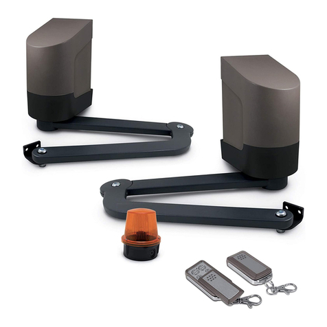
Avidsen WEAT C2N Installation instructions

Installation and owner’s manual
DRIVE KIT FOR
SLIDE GATES
WEAT C2N
This document is part of the kit and must always be kept with it.
Important: Read this manual in full and follow the safety instructions
BEFORE INSTALLING, USING or SERVICING this product.
EN 12–08 V1

WEAT C2 N - V1
ABD
C
Ph NT
T
WEAT B2N
WEAT G2N
WEAT V2N
WEAT C2N
30 mA
10 A
230 VAC
NPh
TEST
The connection must be made according to standards in force* in the country where the
automatic system is installed, for wiring as well as for protection of people and goods.
(You must contact a qualified and experienced person).
The protection must be accessible and, in case of shutdown, make sure that an accidental re-
connection is not possible.
N
T
Neutral (blue wire)
Earth connection
(yellow and green wire)
Ph Phase, at the level of the automatic system connect it
to the terminal near the fuse “D”
A30 mA differential, to be tested once a month with the “test” button. (Ground Fault
Circuit Interrupteur)
BProtection by 10 A circuit-breaker (2 poles: neutral and phase)
CPower cable and sheath, according to the country where installed (RO2V cable of 3 x
1.5 mm² up to 30 metres and 3 x 2.5 mm² above in a 40 mm diameter orange cable
duct, for France)
* NF C 15-100 for France
“Electrical” connection of your automatic system

WEAT C2 N - V1
Caution for or the safety of individuals and property, follow these instructions and keep them in a
safe place.
We recommend you carefully read and follow these instructions. Improper use and programming can be
dangerous and can cause serious injury.
If you are unsure about installing this product, seek assistance from our technical department.
This symbol is used to highlight points that could be a potential source of danger. Ensure procedures
and safety standards in force in the installation country are followed.
This system complies with the essential requirements and other provisions of the 1999/5/CE directive.
The installation of an automated gate or garage door system must comply with the 98/37/CE “Machinery
Directive” and particularly with the
EN 12445:2001; EN 12453:2001; EN 12978:2003; EN13241-1:2003
standards. These standards allow the compliance of an automated system to be declared.
This automated system must be installed, commisioned and maintained by qualified and specialised
individuals.
a - WARNING
- Analyse the risks of your installation, make a list of the essential safety requirements in appendix I of the
machinery directive.
To complete this document, you can, if required, contact a professional installer.
- The manufacturer of this automated system will not be held responsible if installation and usage guidelines are
not followed.
- Improper installation or adjustment can cause serious injury to users or to the installer.
- The following warnings are an integral and essential part of the product and must be provided to users.
- Read these warnings carefully because they provide important information about installation, use and
maintenance.
- Keep this manual and give it to individuals who will use the installation when you no longer use it.
- Incorrect installation or improper use of this product could be very dangerous.
- The manufacturer will not be held responsible for the integrity of the product, and for the safety and
operation of it, if incompatible devices and/or components are installed.
- For the repair or construction of parts, original replacement parts must only be used.
- The installer must provide all information regarding the functioning, maintenance and use of each of the parts
and the overall system.
- The installation, electrical connections, and adjustments must be professionally done by a qualified and
specialised individual.
b – CORRECT PRODUCT SELECTION
Check that the product for residential use that you have purchased suits your existing gate and that you have all
the necessary parts to ensure “safety”. Particularly check the technical features (weight and size of the gate, full
or open-work, sliding or stable door etc.)
You must have all the parts to ensure “safety” either in the kit or in option (for example the sensor bar for
open-workl sliding doors)
If you are unsure, contact a professional.
c – CHECK THE CONDITION OF YOUR GATE
Make sure that your gate can support your automated system, by checking the solidity of hinges or sliders, that
the structures are able to take the screwed and moveable automated system parts, that the clearance area is
clear and well visible, that it is in general good condition and that it opens and closes easily when you use it ma-
nually….
1. GENERAL SAFETY INSTRUCTIONS

WEAT C2 N - V1
Concrete structures must be professionally made; if required, contact a professional.
A gate or door in poor condition or badly installed cannot be automated. If you are unsure, contact a
professional.
d – RECOMMENDATONS FOR INSTALLING YOUR AUTOMATED SYSTEM
Badly handled or damaged parts must be returned to us for checking or repair.
- Check that the clearance area for operators (worm screws, arms or sliders) is clear and obstacle-free (cut bushes
and hedges if necessary).
- Do not make any changes to parts of this automated system that are not authorised in this manual. These
changes could make its use very dangerous. The manufacturer will not be held responsible for any damage resul-
ting from these changes and will cancel the guarantee.
- All installation and maintenance must be done with an electrical supply and optional disconnected battery (and
highlight your presence in a passageway with a sign for example).
- Always use appropriate tools which are in good condition.
- Fixed and moveable parts must be solidly and professionally attached and stable for the duration.
- Do not expose any parts of this kit to rain or strong heat during installation. Using the automated system in
these conditions can be very dangerous.
- Do not submerge parts of the automated system in water or any liquid substances. Using the automated
system in these conditions can be very dangerous.
- If liquid gets into the automated system, disconnect it immediately by following the safety procedures for the
electrical network. Using the automated system in these conditions can be very dangerous.
- The installer must check that the temperature during use is complied with.
- The installer must ensure that access to the manual release button is always available.
- The installer must ensure that moveable or fixed parts are protected from shock (protect them if required).
Moveable parts must be clear and obstacle-free.
- The installer must check that there are no crushing or cutting areas. All safety procedures must be followed to
eliminate these problems.
- The alignment of photo-electric cells is very accurate; ensure that their connections are stable and on a flat
surface.
- The flashing light must be visible from the road and is obligatory.
e – ELECTRICAL CONNECTION AND INSTALLATION
The EN 12445 standard outlines the test methods to check the gate’s automated systems.
- The installation, electrical connections, and adjustments must be professionally done by a qualified and specia-
lised individual according to the standards in force in the country where this product is installed (NF C 15-
100 for France).
- Use 3 x 1.5 mm2 cable up to 30 metres long and 3 x 2.5 mm2 beyond that. Protect the unit with a differen-
tial 30 mA circuit-breaker and with a bipolar 10A circuit-breaker. Check your electrical installation is properly
earthed. Have an all-pole cut-out device in the network and an emergency shutdown button close to the
automated system is recommended.
- We recommend you supplement your electrical installation with a surge suppressor.
- The ligthing system in the clearance area around the gate must be grounded or double insulated
- Prior to installation, ensure that covers and protections are properly screwed or well fitted together.
- Only modify the original parameters if required and with care (speed, sensitivity, etc.).
- For safety, at installation, ensure that an individual is close to the gate.
- The electronic card is a high technology sensitive product and does not tolerate mishandling, in particular
around the radio card and its adjustment potentiometers.
- All safety parts must be checked prior to validating the installation.

WEAT C2 N - V1
f – PROTECT THE ENVIRONMENT
- Packaging materials (cardboard, plastic, polystyrene, etc) must not be dumped and must not be left within
children’s reach, because they are a potential source of danger.
g – USERS GUIDE
Do not touch the parts of the automated system and the gate itself when it is moving
(The gate must installed at a distance from children’s play areas).
Remote controls, keyboards or auxiliary controls must only be accessible to authorised individuals.
Warning to users (Must be read prior to first use).
- Keep remote controls away from children (they are not toys)
- Keep children away from moveable parts
- The product must be used for the purpose for which it was designed and must be installed professionally
especially for assembly fittings and bases. Any other use must be considered improper and therefore dangerous.
Also, the information in this document could be changed without notification. It is provided for information. CFI
declines all responsibility.
- Keep products, devices, documentation and all other parts in a safe place.
- Changing the parameters must be done by a qualified and specialised individual.
- Should there be a problem, however minor, cut the electrical supply (disconnect the optional battery), disengage
the motor(s) and call a qualified and specialised individual.
- Regularly checking the condition and proper functioning of photo-electric cells is one of the important points
for the safety of individuals and property.
- You are responsible for maintaining your automated system.
- Connect the electrical supply; after installation you must completely check the safety elements (flashing light,
photo-electric cell, etc.).
Flashing light: Check that it is working properly and can be seen from the road and close to the gate or door.
Photo-electric cells: Check that it is working properly with the closing movement.
Optional sensor bar: Check that it is working properly, use a piece of wood to check it.
Optional emergency button: Check that it is working properly.
Important:
The fitter at the end of the installation must check that the motor conforms to paragraph 5.1.1.5 of the EN
12453 standard (limitation of forces article 5.2.1 of the EN 12453 standard).
Starting of the leaves: The force must be sufficient and not excessive to open and stop the gate, without re-
bound and without distortion, you should, if necessary, adjust the setting VR1 – (FOR), this setting controls the
speed of the leaves, and must be adapted to the type of the gate used (heavy, light, full or open-work….).
Stop on obstacle: To avoid any risk of injury, the force at the end of the leaf shall not exceed 15 kg of driving
force whatever the conditions of use. If necessary, consult a qualified fitter.
If necessary, you have to adjust the setting VR5 (OVL) according to the type of gate used (For safety reasons,
you must be able to stop the course of the gate by hand).
Lighting system of the clearance area around the gate: Check that it is working properly (the lighting duration
is temporised).
Reminder: The person who installed the automated system is responsible for the installation.
h - MAINTENANCE
- Keep the installation in good working, electrical, mechanical condition and regularly check the condition and
proper functioning of the various parts.
We recommend you check your automated system and the safety elements every 6 months at the most or after

WEAT C2 N - V1
every problem or external intervention.
This kit does not need any lubrication; you should check the condition of connections and the various electrical
cables and completely test the safety units (photo-electric cells, flashing light, obstacle stop, sensor bar, emer-
gency shutdown, etc.).
Check the condition of hinges for a leaf gate, wheels for a sliding gate and sliders for a garage door (lubricate
these parts if required)
REMINDER : DO NOT FORGET TO CUT THE 230 V POWER SUPPLY AND THE BATTERIES BEFORE ANY
PROCEDURE ON MOTOR UNITS or POWER SUPPLIES.
- To ensure the product performs at its best, it is essential that those who install the automated system comply
with current legislation and with safety regulations.
- Installation and cleaning must be documented (document to be completed on the next page).
This documentation must be kept by the user and made available to competent staff.
DOCUMENT TO BE COMPLETED WHEN MAINTAINING YOUR AUTOMATED SYSTEM
As previously stated, you must regularly check your automated system every 6 months at the most and note the
points checked and your comments.
This automated system must be checked and maintained by qualified and specialised individuals in com-
pliance with current standards in the country of use.
a – Cut off the electrical supply (disconnect the optional batteries) and then check the electrical cables, the
various connections and working parts. All worn or damaged parts must be replaced.
b – Re-connect the electrical supply and completely check safety elements.
Remote controls: Check the range of the remote control, change the battery if necessary.
Flashing light: Check that it is working properly, check its condition and that it is visible from the road.
Photo-electric cells: Check that it is working properly with the closing movement and is in good condition.
Optional sensor bar: Check that it is working properly, use a piece of wood to check it and check its
condition.
Optional emergency button: Check that it is working properly.
Obstacle stop: Place a 15kg weight in the passageway at the end of the stable door (use a bag of sand or buckets
of water for example); on closing, the gate must stop.
Lighting system of the clearance area around the gate: Check its condition and that it is working properly; if
necessary change the bulb.

WEAT C2 N - V1
Installation address :
Reference of your automated system: WEAT _ _ _
Serial number (above the bar code) : CFI/0811/_ _ W _ _ / _ _ _ _
Date of purchase : _ _ / _ _ / _ _ _ _ Shop:
Installed on: _ _ / _ _ / _ _ _ _ by:
Date Description of procedure Procedure
carried out by:

WEAT C2N – V1 - EN 2
CONTENTS
0. SAFETY INSTRUCTIONS
1. KIT CONTENTS................................................................3
2. COMPLETE INSTALLATION...........................................4
3. SPECIFICATIONS ............................................................4
4. DIMENSIONS....................................................................5
5. TYPICAL CONNECTION..................................................5
6. GATE CHECK...................................................................6
7. LOCATION OF MOTOR ................................................... 8
8. INSTALLATION ................................................................9
9. CONTROL BOX..............................................................10
10. RADIO CONTROLS......................................................15
11. TROUBLESHOOTING GUIDE......................................16
12. SENSOR BARS (FOR SAFETY) OPTIONAL ..............17

WEAT C2N – V1 - EN 3
•1 motor assembly with built-in electronic board.
•1 adjustable base
•4 m reinforced nylon rack
in 50 cm modules
•2 limit stops to be installed on rack
•2 four-channel remote controls
•1 flashing beacon (to be positioned on post so as to be visible
from street)
•1 set of photocells
(position 40 cm max. from bottom of post)
•1 lighting module (required to light the gate’s
path of movement)
•1 operator control relay powered
by a 12 V supply from a door phone
(connect the red and black wires on
the 12 V door phone control and the
2 white wires on the operator board’s
auxiliary control)
Options (not supplied)
WEATEM 4: extra remote control - WEATCC 2: key switch
WECACV 70002: Wireless keyboard - WEATCE 2: 50 cm length of rack
WEATBT B2: backup battery kit that provides for WE 8111 BIS and ATCR 2
WEATAN 2:external antenna for extended range - WEATDT 80301:emergency bar 2 m.
WEATER 3: Two WEATEM 3 remote control units and one12 VDC, 2-channel radio
receiver.
WE 8111 BIS
A
TCR 2
1. KIT CONTENTS

WEAT C2N – V1 - EN 4
Max. weight of leaf 350 kg
Max. width of gate Any
Power supply 230 VAC 24 VAC
Current consumption 0.9-3.5 A
Power 40 W
Force 500 N
Operating temperature -20°C / +55°C
Degree of protection IP44
Limit switches Electromechanical
Opening speed 10 m/min.
2 COMPLETE INSTALLATION
OPTION:
WEATDT 80301
Mesh, grille or slatted type
gates: install optional
safety bar
WEATDT 80301
on the pinch point
3 SPECIFICATIONS

WEAT C2N – V1 - EN 5
4. DIMENSIONS
5. TYPICAL CONNECTION
Battery kit
(option)
WEATBT B2
Flashing beacon
Emergency bar
(option)
WEATDT 80301
230 V~ mains power supply
Neutral
Live
230 V
~
mains power
earth
After protecting the
earthed power supply with
a 10 A two-pole circuit
breaker and a 30 mA
Ground Fault Cicrcuit
Interrupter , connect it to
the terminal block inside
the motor assembl
y
.

WEAT C2N – V1 - EN 6
In order for correct gate operation, both the gate and the operator must meet certain construction and
operation requirements. Damage may result if these requirements are not met.
Smooth opening and closing is the main requirement. A good gate is one that can be opened simply by
pushing on it with a hand.
GATE CONSTRUCTION: The gate’s structure must be adjustable and true. No automatic latches should be
fitted on the gate.
BOTTOM TRACKS: For smooth gate opening and closing, the track must be true and perfectly horizontal
(levelled). The track may have a round or V-shaped section, as illustrated by Figure 1.
Important: a bumper must be placed on the bottom track to stop the moving gate (Fig. 2) and prevent it
sliding off the track and falling over and injuring someone.
TOP TRACKS: A minimum of two tracks must be installed. The tracks must be linear to ensure gate stability.
A few installation examples are illustrated in Figure 3.
ROLLERS: The shape and dimensions of the rollers must be compatible with section of the bottom tracks.
The rollers must be fitted near each end of the gate and must be kept in good condition to ensure smooth
opening and closing.
Fig. 4
6. GATE CHECK
Rounded section
V
-
shaped section
Fig. 3

WEAT C2N – V1 - EN 7
Installing the rack and limit cams
Important: the kit comes with four 50 cm lengths of rack to be installed to the left of the gate and four 50 cm
lengths to be installed to its right. The limit cams must be installed at both ends (see drawing below). To do
so, interlock all four sections with tenons to the left then interlock the four sections with mortises to the right.
Install to right of gate
Install to left of gate

WEAT C2N – V1 - EN 8
fig. 4
7. LOCATION OF MOTOR
The pinion and rack must be separated by a
clearance of 2 or 3 mm.
If this clearance is greater, the pinion will not be
able to drive the rack.
If it is less, the gate’s entire weight will be placed on
the pinion.
Grub screw
Nut E
Nut F
2 to 3 mm
40 mm
10 mm

WEAT C2N – V1 - EN 9
Preliminary checks:
Before installing the motor, make sure:
The gate slides smoothly (rollers properly lubricated),
The gate is fitted with mechanical stops (opening and closing).
Installing the motor:
Unless otherwise indicated, all measurements are given in millimetres.
•After pouring a concrete pad and allowing it to cure, insert anchor bolts into the pad and fasten the base.
The base should be clean and level. Maintain the axis between the edge of the plate and the rack B.
Route the cable conduits through the holes Ain the plate (see Figure 1).
•Fasten the motor to the base using the four screws supplied C. Adjust the motor horizontally by sliding it
into the slots in the anchor lugs D(Fig. 2).
•If the motor is fastened to an irregular surface, adjust the motor vertically. To do so, use grub screws and
three nuts on each screw, as illustrated in Figure 3. Adjust the nuts Eand F until the motor is vertical.
•Adjust the motor so that it is horizontal both depthwise and widthwise.
•Fastening the rack: loosen the motor, slide the gate over and fasten the rack along its entire length. A
clearance of 2 or 3 mm must separate the pinion and the rack from one end of the rack to the other
(Fig. 4).
•Adjusting the stops: fasten the stops G on the rack (Fig. 5) so that the gate will stop approx. 20 mm
before the end stops, which must be fitted. To do so, use a 3 mm bit to drill two holes into the rack. Use
the stop as a jig. Fold the front of the stops slightly to make it easier to guide the switch onto the stops.
To prevent premature wear, fit the drive unit so that
the pinion moves at a 90° angle (see illustration
o
pp
osite
)
.
8. INSTALLATION
Direction of o
p
enin
g
Direction of opening

WEAT C2N – V1 - EN 10
Unlocking and locking the drive unit
Insert the appropriate key into the slot on the
device. Turn the key clockwise to release the
lever and pull out the lever as illustrated.
Spare parts:
Use original spare parts only.
Do not install the drive on inclined gates.
Make all connections with the electrical power supply turned off.
Connecting and turning on the unit
•Read the General Safety Instructions before installing the operator.
•Install a switch / isolating switch on the mains in accordance with current standards.
•Connect the power and control cables by following the requirements below:
The STOP button or switch connected must be equipped with a manual release. If you do not
wish to use it, bridge the STP input to ground (ground terminals are symbolised by ↓).
Make sure all the inputs on the terminal block are wired correctly and in proper working order
.
Motor force
Pedestrian control
Emergency stop
Auxiliary control
10 A fuse
Learn button
P2/RADIO
Battery pack
Motor
Obstacle detection
Learn button
P1/SET
Backu
p
transforme
r
Radio channel
selector switch
Photocells
Limit switches
Radio antenna
Beacon
The Off button or switch connected must be equipped with a manual release. If you do not
wish to use it, bridge the STP input to ground.
9. ELECTRONIC CONTROL BOARD
Pause time Obstacle reaction time
FOR PAU OBS OVL

WEAT C2N – V1 - EN 11
See page 12 for the
motor wires
WE 8111 Bis, supplied
ATCR 2, supplied
Optional
antenna
WEATAN 2
Manual control
(
button
,
door
p
hone
,
etc.
)
Partial o
p
enin
g
control
EMERGENCY STOP
Button with normally closed contact
(The kit is supplied with the 2 terminals bridged. Remove
the bridge if you install a button or an emergency bar)
Optional emergency bar instead of our series
connected with a Stop button:
*Remove the wire linking the 2 terminals.
Touching the emergency bar stops the gate.
Remove the obstacle and reset with the remote
control.
12V flashing beacon
No specific polarity
Motor limit
switches, see
p.12
Control for lighting the
gate's path.
white red
Neutral
Live
230 V~
protected
blackwhite
2-wire door phone or video
door phone
Automatic mode is not possible if photocells are not fitted
If the red LED inside the RX
p
ortion is lit, the
p
hotocells are ali
g
ned.
Do not forge
The shunt between
COM and GND
Alignment
LED: ON if
alignment
correct
COM TXF COM VA PHO
Lamp : 100 W max.
Delay fixed : 2 min 30

WEAT C2N – V1 - EN 12
RIGHT
MOTOR
ASSEMBLY
LIMIT SWITCHES: brown - white - black MOTOR WIRES: red-black
FOP
LIMIT SWITCH
MOTOR WIRES: black-red
LIMIT SWITCHES: brown - white - black
LEFT
MOTOR
ASSEMBLY
LIMIT SWITCH
To
p
view
V
iew from motor side
V
iew from motor sideTo
p
view
FCL
FOP
Limit switch connection: ori
g
inal
OPENS TO RIGHT
OPENS TO LEFT
white brown black white
white brown
black white
After protecting the earthed power
supply with a 10 A two-pole circuit
breaker and a 30 mA Ground Fault
Circuit Interrupter, connect it to the
terminal block inside the motor
assembly.
Neutral
Live
230 V~ mains
p
ower su
pp
l
y
earth

WEAT C2N – V1 - EN 13
QUICK START-UP
Press button P1/SET for
3 seconds
End of learn procedure
Gate opens for 4
seconds then closes
Motor stops
Paragem do
motor
Green LD1 lit steadily
Gate closes
Safety mechanisms and
motor registered
Motor stopped after 3
seconds
Gate opens
Motor stops
QUICK START-UP
Connect the unit, the power supply, the motor, the photocells and the beacon.
Leave the GATE half open.
Then
Green LD1 off

WEAT C2N – V1 - EN 14
Learn mode
Press the P1/SET button for three seconds.
Learn mode is activated when the green SET LED lights up and with the start up of the motor.
1) The unit performs a pre-opening operation for approx. three seconds.
a) if the gate closes instead of opens, cut the power to the unit and reverse the motor wires.
b) repeat the learn procedure from the start.
2) The unit closes the gate until it comes to a stop and is fully closed.
3) The unit opens the gate completely to learn how long the operation takes and when exactly it should start
slowing down (90% into the operation). Opening ends when the stop is reached by the obstacle check.
4) After a three-second pause, the unit closes the gate completely and exits learn mode.
Changing the settings
If need be, after performing the initial gate test, adjust the following board settings using the trimmers on the
board:
-motor force (trimmer VR 1)
-pause time (trimmer VR 2)
-obstacle response time (trimmer VR 3)
-sensitivity (trimmer VR4)
Warning: for reasons of safety, you should be able to stop the gate using your hand
(15 kilograms pressure on the edge of the door).
The pause time trimmer can also be used to select automatic or jog mode. Turning the trimmer to the end of
the scale will activate automatic mode with a variable pause time of between 0 and 90 seconds. Turning the
trimmer all the way to the bottom of the scale (jog mode) will inhibit automatic mode
ELECTRONIC BOARD SETTINGS
FORCE PAUSE TIME OBSTACLE RESPONSE SENSITIVITY
TIME
‘+’ maximum
jog
‘-’ pause time in
automatic mode
‘-’ lower motor
force
‘+’ stronger
motor force
‘-’ lower
response time
‘+’ higher
response time
‘-’ more sensitive
‘+’ less sensitive
To activate the new
settings, repeat the
learn procedure in
full (page 13).
FOR
PAU
OBS
OVL
Table of contents
Other Avidsen Garage Door Opener manuals
Popular Garage Door Opener manuals by other brands

Doco
Doco RES STF Manuals

Bircher Reglomat
Bircher Reglomat INTRA 50 operating instructions

SAMT
SAMT RGD350 Installation instructions and user guide

SOMFY
SOMFY Elixo 500 3S io installation instructions

Chamberlain
Chamberlain Security + 9902C owner's manual

SOMFY
SOMFY Dexxo Pro 800 - 1000 RTS installation manual