TARGET AUTOMOTIVE LASERTRACK LT 400 User manual

3
Preface 4
Area of application of the Target Lasertrack 5
Contents of the package and optional accessories 5
Important information 6
Installation 6
Transponder alignment 7
Calculation table for the installation of the transponder 8
Testing the operation 9
Important information for all users 9
Frequently asked questions about Target Lasertrack 10
Installation of the LT445 control circuit board and the
LT420 basic transponder 11
Programming the Target Lasertrack 12
Technical specifications 13
Conditions of guarantee 14
Connection diagram 76
Table of contents
Manual Target Lasertrack
English

4
You have just purchased a Target LaserTrack and are now the owner of a very advanced Class 1 laser
remote control system which can be used for various actions. The system is unique because it allows you
to open your automated gate, garage door or turn on or offthe outdoor lighting fully automatically, i.e.
without pressing a button, at a distance equal to that of radiographic remote control systems.
The unique code of your vehicle is automatically recognized by the basic transponder(s) as soon as you
are within range through the patented “trigger and reply” technology.
The Class 1 laser technology used is safe, reliable and is more user-friendly than conventional remote
control systems.
The automotive industry has also discovered the advantages of laser technology. Nissan already
introduced an “adaptive cruise control system” which automatically determines the distance to the cars in
front of it and which adjusts the speed accordingly if required. Laser technology is also widely applied for
distance measuring systems that can be mounted in the vehicles after these have left the factory.
We believe our system can increase the comfort of driving and wish you many happy years using your
Target L aserTrack.
We recommend you read this manual thoroughly in order to get fully acquainted with the system.
Target Automotive BV
Preface
5
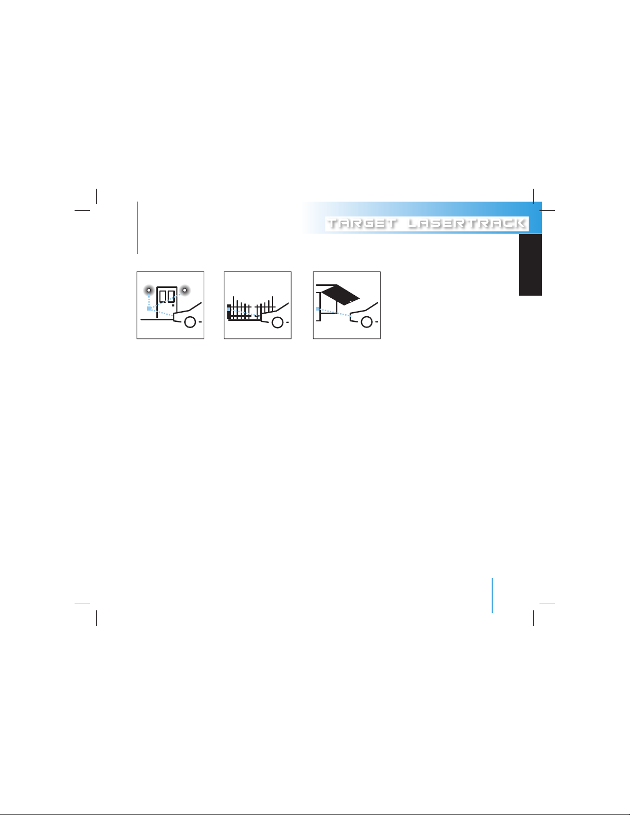
1. Exterior lighting 2. Access control 3. Garage doors
The Target Lasertrack is delivered in 3 packages:
LT 400 Vehicle System:
■1 LT 400 car transponder (refer also to the accessories)
■1 LED
■1 Piezo signal device
■1 Water leveller
■All required connection and fastening material
LT 430 House System:
■1 LT420 basic transponder
■1 Control circuit board LT445
■1 Water leveller
■All required connection and fastening material
LT 450 Complete System:
■1 LT 400 car transponder
■1 LT420 basic transponder
■1 LT445 control circuit board
■1 Piezo signal device
■1 LED
■1 Water leveller
■All required connection and fastening material
Manual Target Lasertrack
Area of application of the Target Lasertrack
English

6
Accessories (optional)
A special waterproof LED transponder for motorcycles is available. For motorcycles order the Target
LT400-M. The control elements of this set are completely waterproof and weatherproof. This system also
has a special optical signalling system that is always visible to the motorcyclist.
Important information
Nearly all laser systems using infrared light emit their information on a frequency of 904 nanometre
(this is the wave length which emits infrared laser light). This is also true for the LaserTrack. This wave
length has become the worldwide standard. Even the police laser guns emit speed measurements on
this wave length. Target LaserTrack is the only system that has intelligent electronic technology that
can recognize the signals of laser guns and other laser systems that use the same wave length; e.g.
hunting or surveyor range finders, police laser systems or vehicles fitted with laser based adaptive
cruise control systems. After recognizing a an infrared signal that is not its own, Target LaserTrack
temporarily shuts itself offto prevent failures and, for example, to allow a laser speed measurement to
take place. You are informed of this through a visual and audio signal.
Installation
Follow the instructions below to the letter to ensure that the system performs optimally.
Mounting and connecting the LT400 car transponder
1. Mount the transponder preferably in the middle at the front of the vehicle (preferably very near
to the number plate). The transponder may also be mounted behind the grill. The free passage
opening should be larger when the distance from the transponder to the opening is greater.
Refer to the calculation table on page 8.
2. Mount the transponder using the tee bolt and mounting bracket included in the package. Refer to
Transponder Alignment on page 7.
3. Ensure the transponder is aligned correctly. Refer to Transponder Alignment on page 7.
4. Lead the transponder cable through the engine compartment. Use the cable guides already present
when possible. Do not pull the cable too tightly and do not kink the cable. Lead the cable through
the existing grommet to the interior. Connect as indicated in the diagram on page 76.
Important information

7
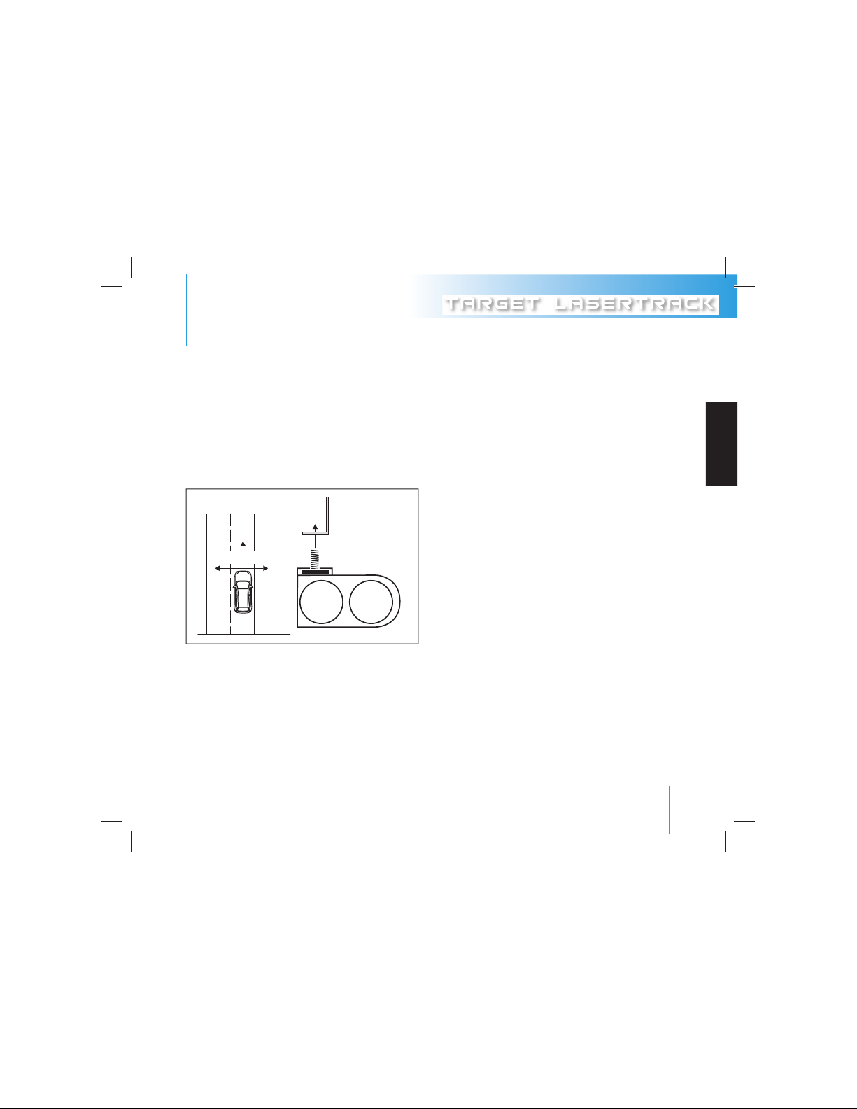
The correct alignment of the transponder is very important. It should be aligned correctly vertically
and horizontally. Vertical alignment: Upwards/Downwards. The transponder can be adjusted upwards
or downwards by turning the angle iron included in the package. This is the vertical alignment. Make
sure the vehicle is level. Use the water leveller included in the package to adjust the vertical position.
Place the water leveller just above the transponder and fasten the transponder in the correct position.
Horizontal alignment: Left/Right. The transponder can be turned around itself using the tee bolt. This
is the horizontal alignment. The transponder should be placed at a right angle of the vehicle.
90°90°
Manual Target Lasertrack
Transponder alignment
English

8
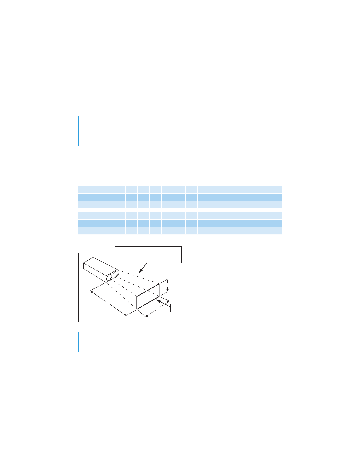
Use the table below when mounting the transponder in the grill or behind a vent hole of the vehicle.
Mounting the Target LaserTrack using the parameters below guarantees maximum performance.
Measurements are in millimetres
Minimum height (H) 6 8 9 10 11 13 14 15 16 18 19 20 21
Minimum width (W) 16 18 21 23 26 28 31 33 36 38 41 43 46
Maximum depth (D) 0 12 24 36 48 60 72 84 96 108 120 132 144
Minimum height (H) 23 24 25 26 28 29 30 32 33 34 35 37 38
Minimum width (W) 48 51 53 56 58 61 63 66 68 71 74 76 79
Maximum depth (D) 156 168 180 192 204 216 228 240 252 264 276 288 300
Calculation table for the installation of the transponder
H
W
D
Cross-section of laser beam increases
with increase in distance D
Grill/vent opening

9
The correct operation of the system can be tested after the Target LT400 has been installed according
to the instructions:
1. Switch the system on by starting the vehicle (if the switch has been added then it must be set to ON).
Result: The system emits a short audio signal and the LED is switched on for 2 seconds. The LT400
will be in test mode for 10 seconds only.
2. Test the operation of the laser receiver using an infrared remote control device (for audio or video
equipment). Hold the remote control device in front of the transponder lens (at a distance of
approximately 10 cm) and at the same time press a button of the remote control device.
Result: The system emits a warning signal and the LED is switched on.
3. Stop pressing the button of the remote control device when you are satisfied that the system is
functioning correctly.
Result: After the last received signal the LED will be switched on for 10 seconds. After the 10 seconds
have elapsed the system will emit two short audio signals. The LT400 is now in the stand-by mode.
Important information for all users
■Check frequently whether the lens of the transponder is dirty. The effect of dust and grit on the
functioning of the system is very limited. Objects that cover the lens completely, such as leaves or
insects, should be removed at once.
■Check frequently whether the housing and the lens of the transponder show signs of damage.
Contact your dealer if the lens is damaged.
■A dealer should check the tuning of the transponder periodically (for example, when the vehicle is
serviced).
Manual Target Lasertrack
Testing the operation
English

10
1. Can other Target LaserTrack users gain access to my grounds or garage?
No, Target LaserTrack has more than 4.5 thousand million unique codes. Only vehicles for which the
code has been programmed in the basic transponder can gain access.
2. Does the Target LaserTrack laser beam damage the eye?
No, the Target LaserTrack is a Class 1 laser and is, therefore, completely safe.
3. Can I control other systems or equipment than those mentioned in the manual using the
Target L aserTrack?
Yes, in principle all electrical systems can be switched on and offremotely using the Target
LaserTrack. We recommend contacting the dealer for the system before applying the Target
LaserTrack.
4. Does the Target LaserTrack meet all the legal requirements and can I legally use the system
anywhere?
Yes, the Target LaserTrack meets the highest European standards for automotive accessories.
Although interference with other equipment such as laser guns cannot be ruled out, the system
may be used everywhere for the purpose it was developed. The system may not be used for other
purposes than that for which it was developed by the manufacturer.
5. Is the Target LaserTrack influenced by police laser guns or other infrared laser systems?
Yes, every laser gun or other laser systems that emits on a frequency of 904 nanometre is
recognized by the Target LaserTrack as an external source of interference. The Target LaserTrack
shall always switch itself offafter a few seconds to prevent mutual interference.
Frequently asked questions about the Target Lasertrack

11
Installation of the LT445 control circuit board and the LT420 basic transponder
Mounting the LT420 basic transponder
1. The LT420 basic transponder is mounted in the same way as the LT400 car transponder. Ensure that
the transponder is mounted at a location where it can detect the arriving vehicle. Avoid mounting it
behind bushes or other obstacles.
2. Mount the LT420 at the same height or as near to it as possible as the LT400 on your vehicle. This
is especially important to guarantee the communication between the vehicle transponder and basic
transponder at a short distance.
3. Make sure the cable is long enough to reach the location where the control circuit board is mounted.
4. We recommend using 2 x 25 mm drill holes site by site.
5. Take care not to push too hard on the front lens of the LT420 when fixing in position - Do not use
sharp instruments.
6. Ensure that the cable cannot be pinched. Especially when the system is used to open and close gates.
7. Connect the plug of the LT420 to the control circuit board.
8. Connect power to the home controller circuit board using the power supply provided or utilise power
from the gate controller or garage door controller if 20-27 V AC or DC.
Two LT420 transponders can be connected to the control circuit board (depending on the actual
circumstances).
Connecting the LT445 control circuit board to the gate or garage door
The control circuit board is connected to the garage door or gate differently depending on the brand
and type of door or gate. Refer to the garage or gate system dealer for instructions for the connection
of the system to your gate or door.
The switching offcan be delayed by 5 to 120 seconds when the potentiometer is connected to the
control circuit board. Turn the potentiometer in the direction of the arrow to increase the delay.
The control circuit board should be placed in a separate waterproof cabinet if it cannot be placed inside
the gate or garage door switch box.
Manual Target Lasertrack
Installation and connection
English

12
1. Park your vehicle at a few meters distance and in line with the basic transponder. Make sure that the
LT400 is in stand-by mode.
2. Press the BUTTON-1 or BUTTON-2 button (depending on the group it is connected to) on the
control circuit board for 2 seconds.
Result: The corresponding LED blinks. LED 10 shall blink for 10 seconds and it will subsequently start
flashing when the code from the LT400 is received. The code of the vehicle is saved in the memory.
OR
Result: The corresponding led blinks repeatedly for 30 seconds after which it returns to the usual
flashing pattern. This means that the code of the vehicle has not been received. Check the position of
the vehicle and the basic transponder and repeat the procedure from step 2 onwards.
A maximum of 50 vehicles can be programmed into the system in the above manner. Program the
second transponder in manner described above if you have connected two LT420 transponders to a
single control circuit board.
Important: The car transponder concerned has to be reset after programming the LT400 car transponder.
The LT400 switches offafter a programming cycle to prevent the gate or garage door to be opened
immediately.
Deleting vehicles from the basic system memory
All the codes saved in the memory of the connected transponder shall be deleted if you press BUTTON-
1 or BUTTON-2 for more than 5 seconds. The LED shall blink 5 times to confirm it.
The vehicles that should have access should be programmed into the memory again. All codes are
retained in the event of a loss of power.
Programming the Target Lasertrack

13
LT400
Type of emitter Indium Gallium Arsenide laser diode, Class 1
Type of receiver Infrared photodiode with optical and electronic amplifier
Wave length 904 nanometre
Unique codes > 4.500.000.000
Measurements in millimetres Transponder 75 x 39 x 22 (l x w x h)
Transponder housing Aluminium, waterproof
Supply voltage 13.8 volt DC (nominal)
Acoustic signalling 87 dBA.
Period of transmission after trigger Maximum 8 seconds, reset time is 60 seconds
Power consumption 500 mA max.
LT420
Type of receiver Infrared photodiode with optical and electronic amplifier
Wave length 904 nanometre
Max. number of memory slots LT400 50
Measurements in millimetres Transponder 75 x 39 x 22 (l x w x h)
Transponder housing Aluminium, waterproof
Supply voltage through the LT445
LT455
Supply voltage AC/DC 20–27 V (max.)
Maximum relay load 3 A 12 – 250 V AC / DC
Switching delay min. 5 - max. 120 sec. Variable through a potentiometre
Max. number of connected
LT420 transponders 2
Power consumption 300 mA max. (with 2 connected LT420 transponders)
Manual Target Lasertrack
Technical specifications
English

14
1. The manufacturer guarantees the reliability of the system. The guarantee is valid for a term of 24
months for what concerns manufacturing and/or material failure and the following (excluding all other):
- If and when the system is used for the purpose for which it was designed and is mounted and
used in the correct manner and under circumstances that can be deemed to be normal, and all this
according to the regulations and/or instructions of the manufacturer.
- If and when the buyer has met all his responsibilities and the buyer informs the dealer at once, and
no later than one week, after detecting the failure or fault and the dealer finds the system in the
state in which the system was at the moment the fault or failure was discovered.
2. The guarantee is valid if and when the buyer has fully registered the product on
www.target-automotive.nl within two weeks after the purchase date.
3. The guarantee is not valid if and when any work has been or is carried out on the system within the
guarantee period without the prior written permission of the manufacturer.
4. The guarantee claim will be processed after the defect system or the part concerned has been shown to
the dealer.
5. To meet the obligations under the guarantee the manufacturer is only legally entitled and obliged to
deliver or repair the system or parts thereof concerned, at the discretion of the manufacturer.
6. The manufacturer is not bound by the guarantee to carry out or pay for the disassembling or
installing of the system or parts thereof. Postage and handling costs are at the expense of the buyer.
7. The manufacturer is never liable for any damage to persons or goods caused by the malfunction or
not functioning of the system.
8. Only Dutch law is applicable to deliveries of the system.
Edition 3/2008
Conditions of Guarantee

15
Deutsch
Vorwort 16
Anwendungsgebiet für den Target Lasertrack 17
Inhalt der Verpackung und Wahlzubehör 17
Wichtige Information 18
Ausrichten des Transponders 19
Umrechnungstabelle für den Transpondereinbau 20
Funktionskontrolle 21
Wichtige information für jeden Benutzer 21
Die am häufigsten gestellten Fragen über Target Lasertrack 22
Einbau der Steuerungsplatine LT445 und des Haupttransponders LT420 23
Programmieren Ihres Target Lasertrack 24
Technische daten 25
Garantiebedingungen 26
Anschlussplan 76
Inhalt
Bedienungsanleitung Target L aser track

16
Mit dem Kauf des Target LaserTrack haben Sie eine sehr moderne Klasse 1 Laser-Fernsteuerung
erworben, die Sie für viele verschiedene Anwendungsgebiete einsetzen können. Das einzigartige an
diesem System ist, dass Sie vollautomatisch, also ohne “einen Knopf” zu drücken, Gartentür, Garagentor
oder Außenbeleuchtung fernbedient aktivieren und deaktivieren können und die den Vergleich mit
den Funkfernsteuerungen nicht zu scheuen braucht. Aufgrund der patentierten “trigger and reply”
Technologie wird der eindeutige Code Ihres Fahrzeugs, wenn Sie in den Empfangs-/Sendebereich
gelangen, automatisch durch den (die) Haupttransponder erkannt. Die hierfür verwendete Klasse 1
Lasertechnologie ist sicher, zuverlässig und bietet größeren Bedienungskomfort als eine konventionelle
Fernbedienung. Auch die Automobilindustrie hat die Vorteile des Lasers erkannt. So hat Nissan bereits
einen neuartigen “ACC” Tempomaten vorgestellt, der den Abstand zum davor fahrenden Fahrzeug
automatisch ermittelt und falls erforderlich die Geschwindigkeit des eigenen Fahrzeugs vollautomatisch
anpasst. Laser wird ebenfalls im großen Rahmen bei Entfernungsmesssystemen eingesetzt, die
nachträglich in Fahrzeugen eingebaut werden können.
Wir sind davon überzeugt, dass unser System wesentlich an einem hohen Fahrkomfort beitragen wird,
und wünschen Ihnen somit mit Ihrem Target LaserTrack ein jahrelanges Vergnügen.
Um die Funktion des Systems zu verstehen, empfehlen wir Ihnen, diese Anleitung sorgfältig
durchzulesen.
Target Automotive BV
Vorwort

17
Deutsch
1. Aussenbeleuchtung 2. Zugangskontrolle 3. Garagentore
Der Target Lasertrack wird in 3 Paketen geliefert:
LT 400 Fahrzeugsystem:
■1 Autotransponder LT 400 (siehe auch Zubehör)
■1 LED
■1 Piezoelektrischer Schallgeber
■1 Wasserwaage
■Alle benötigten Anschluss- und Einbaumaterialien
LT 430 Haussystem:
■1 Haupttransponder LT420
■1 Steuerungsplatine LT445
■1 Wasserwaage
■Alle benötigten Anschluss- und Einbaumaterialien
Wahlzubehör (optionell)
Das folgende Wahlzubehör ist erhältlich: Es ist ebenfalls ein Spezialtransponder für Motorräder
lieferbar. In diesem Fall muss der Target LT400-M bestellt werden. Die Bedienungselemente dieser
Einheit sind vollständig Wasser- und Witterungsbeständig ausgeführt. Außerdem ist dieses System mit
einer besonderen optischen Warneinrichtung ausgestattet, die für den Motorradfahrer in jeder Situation
gut sichtbar ist.
Bedienungsanleitung Target L aser track
Anwendungsgebiet für den Target Lasertrack
LT 450 Komplettsystem:
■1 Autotransponder LT 400
■1 Haupttransponder LT420
■1 Steuerungsplatine LT445
■1 Piezoelektrischer Schallgeber
■1 LED
■1 Wasserwaage
■Alle benötigten Anschluss- und Einbaumaterialien

18
Praktisch alle Lasersysteme, die Infrarotlicht verwenden, senden Ihre Information im Bereich von 904
Nanometer aus (dies ist eine Wellenlänge in der das Infrarotlaserlicht ausgesendet wird). Dies gilt auch
für LaserTrack. Diese Wellenlänge ist weltweiter Standard. Auch die von der Polizei für Geschwindigkei
tskontrollen eingesetzten Laserpistolen verwenden diese Wellenlänge. Im Gegensatz zu allen anderen
Lasersystemen ist der Target LaserTrack als einziger mit einer intelligenten Elektronik ausgestattet,
die in der Lage ist Laserpistolen und andere Lasersysteme zu erkennen, die die gleiche Wellenlänge
benutzen. Nach dem Erkennen eines “nicht eigenen” Infrarotsignals schaltet sich Ihr Target LaserTrack
automatisch nach einigen Sekunden kurzzeitig aus, um Störungen zu verhindern und eine Lasergesc
hwindigkeitsmessung zu ermöglichen. Sie werden mit Hilfe eines optischen und akustischen Signals
hierüber informiert.
Einbau
Um sicher zu stellen, dass das System optimal funktioniert müssen die nachfolgenden Anweisungen
genauestens eingehalten werden.
Befestigen und Anschliessen des LT400 Autotransponders
1. Montieren Sie den Transponder vorzugsweise an einer zentralen Stelle an der Vorderseite des
Fahrzeugs (vorzugsweise unmittelbarer Nähe des Nummernschildes). Der Transponder kann auch
hinter dem Kühlergrill montiert werden. Achten Sie bei der Montage hinter dem Kühlergrill darauf,
dass die erforderliche “Durchlassöffnung” größer wird, je weiter der Transponder von der Öffnung
entfernt ist. Verwenden Sie hierfür die Umrechnungstabelle auf Seite 20.
2. Montieren Sie den Transponder mit Hilfe des mitgelieferten T-Bolzens und des Befestigungsbügels
(siehe Ausrichten des Transponders auf Seite 19).
3. Sorgen Sie dafür, dass der Transponder korrekt ausgerichtet ist (siehe Ausrichten des Transponders
auf Seite 19).
4. Verlegen Sie das Transponderkabel durch den Motorraum. Benutzen Sie dabei soviel wie möglich
die vorhandenen Kabelführungen. Ziehen Sie das Kabel nicht zu stramm und sorgen Sie dafür, dass
das Kabel nicht zu stark geknickt wird. Verlegen Sie das Kabel durch die vorhandene Tülle in den
Innenraum. Schließen Sie alles an, wie im Schaltbild auf Seite 76 angegeben.
Wichtige Information
19
Deutsch
Es ist wichtig, dass der Transponder korrekt ausgerichtet wird. Dies gilt sowohl für die vertikale als
auch die horizontale Position. Vertikal: Nach oben/nach unten. Durch Verdrehen des mitgelieferten
L-Profils kann der Transponder nach oben und nach unten nachgestellt werden. Dies ist die vertikale
Ausrichtung. Sorgen Sie dafür, dass das Fahrzeug waagerecht steht. Verwenden Sie zum Einstellen der
vertikalen Position die mitgelieferte Wasserwaage. Legen Sie diesen flach oben auf den Transponder
und befestigen Sie den gut bis sobald die korrekte Position erreicht ist.
Horizontal: Links/rechts. Der Transponder kann mit Hilfe des T-Bolzens um seine eigene Achse gedreht
werden. Dies ist die horizontale Ausrichtung. Der Transponder muss senkrecht zur Längenachse des
Fahrzeugs stehen.
90°90°
Bedienungsanleitung Target L aser track
Ausrichten des Transponders
20
Benutzen Sie die nachfolgende Umrechnungstabelle beim Einbau des Transponders im Kühlergrill oder
hinter einer Ventilationsöffnung des Fahrzeugs. Der Einbau mit Hilfe dieser Parameter garantiert die
optimale Funktion des Target LaserTrack.
Maße in Millimetern
Minimale Höhe (H) 6 8 9 10 11 13 14 15 16 18 19 20 21
Minimale Breite (W) 16 18 21 23 26 28 31 33 36 38 41 43 46
Maximale Tiefe (D) 0 12 24 36 48 60 72 84 96 108 120 132 144
Minimale Höhe (H) 23 24 25 26 28 29 30 32 33 34 35 37 38
Minimale Breite (W) 48 51 53 56 58 61 63 66 68 71 74 76 79
Maximale Tiefe (D) 156 168 180 192 204 216 228 240 252 264 276 288 300
Umrechnungstabelle für den Einbau des Transponders
H
W
D
Der Querschnitt des Laserstrahls wird
gemäß der Vergrößerung des Abstandes
D größer
Kühlergrill-/Belüftungsöffnung

21
Deutsch
Nach dem vorschriftsmäßigen Einbau des Target LT400 kann das System auf seine korrekte Funktion
getestet werden.
1. Schalten Sie das System ein indem Sie das Zündschloss einschalten (falls der Schalter eingebaut ist,
diesen in Stellung “Ein” bringen).
Resultat: das System erzeugt ein akustisches Signal und die LED leuchtet für 2 Sekunden. Der LT400
befindet sich nun für 10 Sekunden im Testmodus.
2. Testen Sie die Funktion des Laserempfängers mit Hilfe einer Infrarot-Fernbedienung (von Ihrer Audio-
/ Videoanlage). Halten Sie die Fernbedienung vor die Linse des Transponders (ca. 10 cm Abstand)
während Sie eine der Tasten auf der Fernbedienung drücken.
Resultat: das System erzeugt ein akustisches Signal und die LED leuchtet.
3. Wenn Sie davon überzeugt sind, dass es korrekt funktioniert lassen Sie die Taste auf der ernbedienung
los.
Resultat: Nach dem letzten empfangenen Signal leuchtet die LED für 10 Sekunden. Nach diesen 10
Sekunden erzeugt das System 2 kurze akustische Signale. Der LT400 ist nun in Standby.
Wichtige Information für jeden Benutzer
■Kontrollieren Sie die Linse des Transponders regelmäßig auf Verschmutzung. Staub und Salzanschlag
beeinflussen die korrekte Funktion des Systems nur gering. Dinge die die Linse volständig
verdecken, wie Blätter und Insekten, müssen direkt entfernt werden.
■Kontrollieren Sie das Gehäuse und die Linse des Transponders ebenfalls regelmäßig auf
Beschädigungen. Nehmen Sie mit Ihrem Händler Kontakt auf, wenn die Linse beschädigt zu sein
scheint.
■Lassen Sie den Transponder regelmäßig (beispielsweise bei einer Fahrzeuginspektion) durch Ihren
Händler auf korrekte Einstellung kontrollieren.
Bedienungsanleitung Target L aser track
Testen auf korrekte Funktion

22
1. Haben andere Benutzer von Target LaserTrack auch Zugang zu meinem Gelände oder zu
meiner Garage?
Nein, Target LaserTrack verfügt über mehr als Viereinhalb- Milliarden eindeutige Codes. Nur
Fahrzeuge, bei denen der Code im Haupttransponder programmiert ist, erhalten Zugang.
2. Kann der Laser von Target LaserTrack eine Beschädigung der Augen verursachen?
Nein, der Target LaserTrack ist ein sogenannter Klasse 1 Laser und ist daher vollständig sicher.
3. Kann ich mit dem Target LaserTrack auch andere Systeme / Apparate steuern als die in der
Anleitung aufgeführten?
Ja, im Prinzip können alle elektrischen Systeme mit dem Target LaserTrack ferngesteuert ein- oder
ausgeschaltet werden. Bevor Sie hierzu übergehen, empfehlen wir Ihnen mit Ihrem Händler, bei dem
Sie das System angeschafft haben, Kontakt aufzunehmen.
4. Entspricht der Target LaserTrack allen gesetzlichen Bestimmungen und darf ich das System
überall legal benutzen?
Ja, Target LaserTrack entspricht den höchsten Europäischen Bestimmungen auf dem Gebiet von
Automobilzubehör. Obwohl gegenseitige Störungen anderer Geräte, wie Laserpistolen nicht
ausgeschlossen werden können, dürfen Sie das System, für den Zweck für den es entwickelt wurde,
überall benutzen. Es ist nicht zulässig, das System für andere Zwecke zu verwenden, als der
Hersteller es entwickelt hat.
5. Wird die Funktion vom Target LaserTrack durch Laserpistolen der Polizei und andern Infrarot-
Lasersystemen beeinflusst?
Ja, jede Laserpistole oder jedes andere Lasersystem, das mit 904 Nanometern arbeitet wird durch
den Target LaserTrack als eine externe Störungsquelle erkannt. In alle Fällen schaltet sich Ihr
LaserTrack nach einigen Sekunden aus, um so gegenseitige Störungen zu verhindern.
Häufig gestellte Fragen über Target Lasertrack
This manual suits for next models
2
Table of contents
Languages:


