AXEN AXHW-20a-200L Specification sheet

Sanitary Water Heat Pump
‐Operation and Installation Manual -
AXHW-20a/200L;AXHW-20a/250L;AXHW-20a/300L

1
TABLE OF CONTENT
INTRODUCTION........................................................................................................................................................2
This manual.........................................................................................................................................................2
The unit................................................................................................................................................................ 2
SAFETY INSTRUCTIONS........................................................................................................................................3
Warning................................................................................................................................................................3
Caution.................................................................................................................................................................5
ITEMS INSIDE PRODUCT BOX............................................................................................................................. 6
OVERVIEW OF THE UNIT.......................................................................................................................................7
Parts and descriptions.......................................................................................................................................7
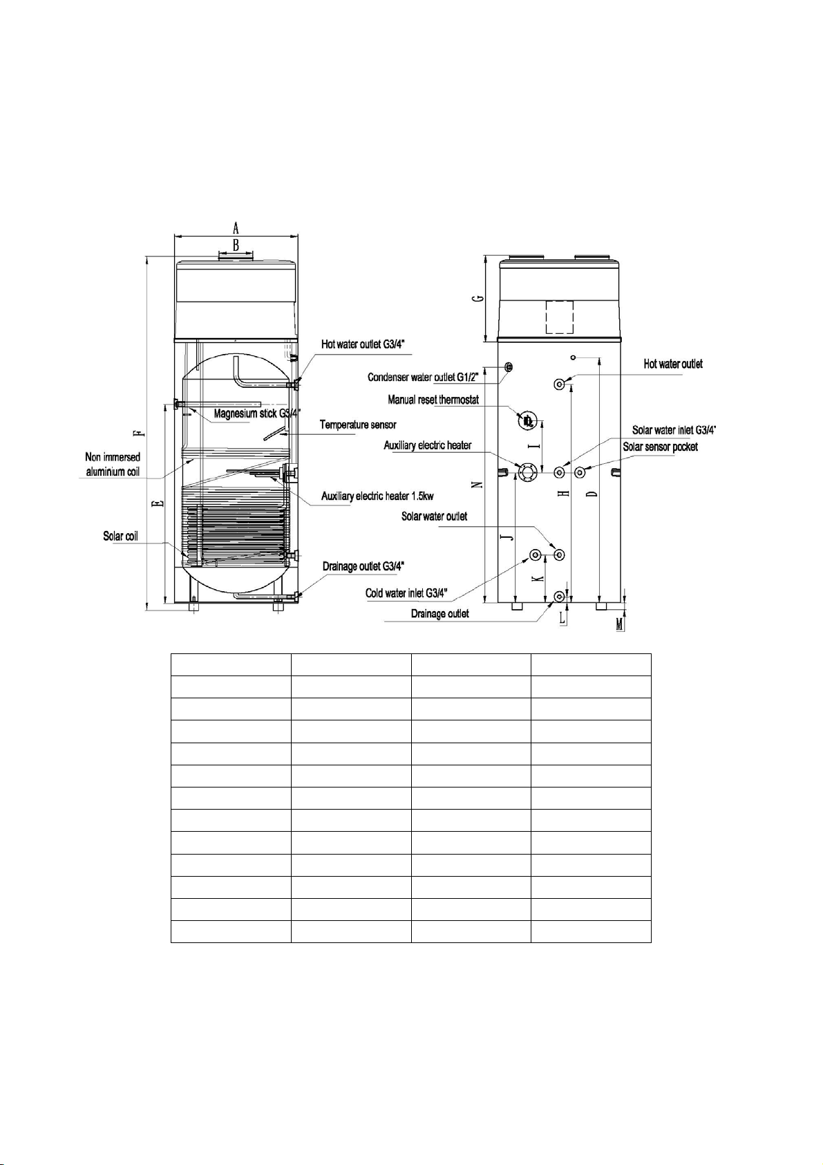
Dimensions......................................................................................................................................................... 8
How to replace the magnesium stick..............................................................................................................9
Schematic overview of the water and refrigeration circuit.......................................................................... 9
INSTALLATION.........................................................................................................................................................10
Transportation...................................................................................................................................................10
Required service space...................................................................................................................................11
Installation overview........................................................................................................................................ 12
Installation positions........................................................................................................................................ 14
Water loop connection.....................................................................................................................................15
Water affusion and water emptying.............................................................................................................. 15
Wire connection................................................................................................................................................16
Trial running...................................................................................................................................................... 16
OPERATION THE UNIT......................................................................................................................................... 17
User interface and operation..........................................................................................................................17
LCD icons.......................................................................................................................................................... 20
PARAMETER CHECKING AND ADUSTMENT.................................................................................................. 22
Parameter list....................................................................................................................................................22
Malfunctioning of the unit and error codes.................................................................................................. 23
MAINTENANCE....................................................................................................................................................... 25
TROUBLESHOOTING............................................................................................................................................ 26
ENVIRONMENTAL INFORMATION..................................................................................................................... 26
DISPOSAL REQUIREMENTS............................................................................................................................... 26
WIRING DIAGRAM..................................................................................................................................................27
TECHNICAL SPECIFICATION.............................................................................................................................. 28
AXHW-20a/***...................................................................................................................................................28
TEMPERATURE SENSOR R-T CONVERSION TABLE...................................................................................30
READ THIS MANUAL CAREFULLY BEFORE STARTING UP THE UNIT. DO NOT THROW IT
AWAY.KEEP IT IN YOUR FILES FOR FUTURE REFERENCE.
BEFORE OPERATING THE UNIT, MAKE SURE THE INSTALLATION HAS BEEN CARRIED
OUT CORRECTLY BY A PROFESSIONAL DEALER. IF YOU FEEL UNSURE ABOUT
OPERATION, CONTACT YOUR DEALER FOR ADVICE AND INFORMATION.

2
INTRODUCTION
This manual
This manual includes the necessary information about the unit. Please read this manual carefully
before you use and maintain the unit.
The unit
The hot water heat pump is one of the most economical systems to heat the water for family domestic
use. Using free renewable energy from the air, the unit is highly efficient with low running costs. Its
efficiency can be up to 3 ~ 4 times more than conventional gas boilers or electrical heaters.
Waste Heat recovery
Units can be installed near the kitchen, in the boiler-room or the garage, basically in every room which
has a large number of waste-heat so that the unit has the higher energy efficiency even with very low
outside temperatures during the winter.
Hot water and dehumidification
Units can be placed in the laundry room or clothing room. When it produces hot water it lowers the
temperature and dehumidifies the room as well. The advantages can be experienced particularly in the
humid season.
Storage room cooling
Units can be placed in the storage room as the low temperature keeps the food fresh.
Hot water and fresh air ventilation
Units can be placed in the garage, gym, basement etc. When it produces hot water, it cools the room and
supplies fresh air.
Compatible with different energy sources
Units can be compatible with solar panels, external heat pumps, boilers or other different energy
sources.
Ecological and Economical Heating
Units are the most efficient and economical alternative to both fossil fuel boilers and heating systems. By
making use of the renewable source in the air, it consumes much less energy.
Compact design
Units are especially designed for offering sanitary hot water for family use. Its extremely compact
structure and elegant design are suitable for indoor installation.

3
Multiple Functions
The special design of the air inlet and outlet makes the unit suitable for various ways of connections.
With different ways of installation, the unit can work as just a heat pump but also as a fresh air blower, a
dehumidifier, or an energy recovery device.
Other features
Stainless steel tank and a magnesium stick assure the durability of components and the tank.
Highly efficient compressor with the R134a refrigerant.
Electrical element available in the unit as a back-up, assuring constant hot water even in extreme cold
winters.
‐
SAFETY INSTRUCTIONS
To prev ent inj ury t o the user, othe r pe ople , or pr ope rty damag e, t he fol lowi ng i nst ruct ions mus t be
followed. Incorrect operation due to ignoring of instructions may cause harm or damage.
Install the unit only when it complies with local regulations, by-laws and standards. Check the main
voltage and frequency. This unit is only suitable for earthed sockets, connection voltage 220 – 240
V~/50Hz.
The following safety precautions should always be taken into account:
-Be sure to read the following WARNING before installing the unit.
-Be sure to observe the cautions specified here as they include important items related to safety.
-After reading these instructions, be sure to keep it in a handy place for future reference.
Warning
Do not install the unit yourself.
Incorrect installation could cause injury due to fire, electric shock, the unit falling or leakage of water.
Consult the dealer from whom you purchased the unit or a specialized installer.
Install the unit securely in a place.
When insufficiently installed, the unit could fall causing injury. The bearing surface should be flat to
bear the weight of the unit and suitable for installing the unit without increasing noise or vibration.
When installing the unit in a small room, please take measures (like sufficient ventilation) to prevent
the asphyxia caused by the leakage of refrigerant.
Use the specified electrical wires and attach the wires firmly to the terminal board
(connection in such a way that the stress of the wires is not applied to the sections).
Incorrect connection and fixing could cause a fire.

4
Be sure to use the provided or specified parts for the installation work.
The use of defective parts could cause an injury due to possible fire, electric shocks, the unit falling
etc.
Perform the installation securely and please refer to the installation instructions.
Incorrect installation could cause an injury due to possible fire, electric shocks, the unit falling,
leakage of water etc.
Perform electrical work according to the installation manual and be sure to use a dedicated
section, fused with 16A.
If the capacity of the power circuit is insufficient or there is an incomplete electrical circuit, it could
result in a fire or an electric shock.
The unit must always have an earthed connection.
If the power supply is not earthed, you may not connect the unit.
Never use an extension cable to connect the unit to the electric power supply.
If there is no suitable, earthed wall socket available, have one installed by a recognized electrician.
Do not move/repair the unit yourself.
If the supply cord is damaged, it must be replaced by the manufacturer or its service agent or a
similarly qualified person in order to avoid a hazard. Improper movement or repair on the unit could
lead to water leakage, electrical shock, injury or fire.
The unit is no intended for use by children.
This appliance is not intended for use by persons (including children) with reduced physical,
sensory or mental capabilities, or lack of experience and knowledge, unless they have been given
supervision or instruction concerning use of the appliance by a person responsible for their safety.
Children should be supervised to ensure that they do not play with the appliance.
Do not tear off the labels on the unit.
The labels are for the purpose of warning or reminding, keeping them can ensure your safe
operations.

5
Caution
Do not install the unit in a place where there is a chance of flammable gas leaks.
If there is a gas leak and gas accumulates in the area surrounding the unit, it could cause an
explosion.
Perform the drainage/piping work according to the installation instruction.
If there is a defect in the drainage/piping work, water could leak from the unit and household goods
could get wet and be damaged.
Do not clean the unit when the power is ‘ON’.
Always shut ‘OFF’ the power when cleaning or servicing the unit. If not, it could cause an injury due
to the high speed running fan or an electrical shock.
Do not continue to run the unit when there is something wrong or there is a strange smell.
The power supply needs to be shut ‘OFF’ to stop the unit; otherwise this may cause an electrical
shock or fire.
Do not put your fingers or others into the fan, or evaporator.
The inside parts of the heat pump may run at high speed or high temperature, they could cause
serious injury. Do not remove the grills on the fan outlet and top cover.
The hot water probable need to mix with cold water for terminal usage, too hot water (over 50℃)in
the heating unit may cause injury.
The installation height of power supply should be over 1.8m, if any water may spatter, the unit can
be safe from water.

6
ITEMS INSIDE PRODUCT BOX
Before starting the installation, please make sure that all parts are found inside the box.
The Unit Box
Item Image Quantity
Domestic hot water
heat pump 1
Operation and
Installation Manual 1

7
OVERVIEW OF THE UNIT
Parts and descriptions

8
Dimensions
Model: AXHW-20a/***
200L 250L 300L
AΦ560 Φ640 Φ640
BΦ177 Φ177 Φ177
D1185 1070 1280
E875 790 1030
F1750 1633 1845
G450 450 450
H1025 890 1130
J600 550 680
K250 250 250
L32.5 32.5 32.5
M35 35 35
N1135 1020 1230
Remark:
1) The extra heat source is optional.
2) The Magnesium stick is an anti-corrosion element. It is assembled in the water tank to avoid the

9
creation of fur around the inside tank and to protect the tank, and other components. It can help to
extend the life-span of the tank. Check the magnesium stick every half year and change it if it
has been used out!
How to replace the magnesium stick :
-Turn the power of the unit ‘OFF’ and pull out the plug.
-Drain all the water out of the tank.
-Remove the old magnesium stick from the tank.
-Replace the new magnesium stick.
-Recharge the water.
Schematic overview of the water and refrigeration circuit
Choose the suitable unit
Please refer to the table below to choose the suitable unit.
Family members Tank capacity
2~3people 200L
4~5people 250L
More than 6 people 300L
Note: The table is just for reference.

10
INSTALLATION
Asked your supplier to install the unit. Incomplete installation performed by yourself
may result in a water leakage, electric shock, or fire.
Indoor installation is highly recommended. It is not allow to install the unit at outdoor
or rain achieving place.
The installation place without direct sunlight and other heat supplies is
recommended. If no way to avoid these, please install a covering.
The unit must be securely fixed to avoid noise and shaking.
Make sure that there’s noremoraaroundtheunit.
In the place where there is strong wind, fix the unit in the location protected from the
wind.
Transportation
As a rule, the unit is to be stored and/or transported in its shipping container in upright position and
without water charge. For a transport over short distance (provided that it is done with care), an
inclination angle up to 30 degrees is permitted, both during transport and storage. Ambient
temperatures of –20 to +70 degrees Celsius are permitted.
-Transport using a forklift
When transported by a forklift, the unit must remain mounted on the pallet. The lifting rate should be
kept to a minimum. Due to its top-heaviness, theunitmustbesecuredagainsttippingover.
To prevent any damage, the unit must be placed on a level surface.
-Manual transport
For the manual transport, a wooden/plastic pallet can be used. Using ropes or carrying straps, a
second or third handling configuration is possible. With this type of handling, it is advised that the
maximum permissible inclination angle of 45 degree is not exceeded. If transport in an inclined
position cannot be avoided, the unit should be taken into operation one hour after it has been
moved into final position.
A
TTENTION: DUE TO THE HIGH CENTER OF GRAVITY, LOW OVERTURNING MOMENT,
THE UNIT MUST BE SECURED AGAINST TIPPING OVER.

11
Required service space
Below you will find the minimum space required to be able to complete service and maintenance
tasks on the units.
Note:
-If air inlet and/or outlet pipes are connected, portion airflow and capacity in heat pump unit will
lose.
-If the unit connects with air ducts it should be DN 180mm for pipes or 180mm internal diameter
flexible hose. Total length of the ducts should not be longer than 8m or the maximum static
pressure should not exceed than 60Pa. Be in mind of bending site of the duct no more than 4m.

12
Installation overview
Note: Solar heat exchange coil is optional.
ATTENTION:
-The one-way safety valve must be installed. If not, it could cause damage to the unit, or even
hurt people. The set point of this safety valve is 0.7 MPa. For the installation place please refer
to the pipeline connection sketch.
-The discharge pipe connected to the one-way safety valve is to be installed in a continuously
downward direction and in a frost-free environment.

13
-The water may drip from the discharge pipe of the one-way safety valve and that this pipe must
be left open to the atmosphere.
-The one-way safety valve is to be operated regularly to remove lime deposits and to verify that it
is not blocked. Please beware of burn, because of the high temperature of water.
-The tank water can be drained through the drainage hole on the bottom of the tank.
-After all the pipes installed turn on the cold water inlet and hot water outlet to fill the tank. When
there is water normally following out from water outlet, the tank is full. Turn off all valves and
check all pipes. If any leakage, please repair.
-If the inlet water pressure is less than 0.15MPa, a pressure pump should be installed at the
water inlet. For ensure the long safety using age of tank at the condition of water supply
hydraulic higher than 0.65MPa, a reducing valve should be mounted at the water inlet pipe.
-Filters are needed in the air inlet. If the unit is connected with ducts, filter in there must be put
forward to the air inlet of duct.
-To fluentl y dra in co nden sat e wat er fr om eva pora tor, pleas e ins tal l the un it at t he hor izo ntal flo or.
Otherwise, please make sure the drain vent is at the lowest place. Recommending the
inclination angle of unit to be ground should no more than 2 degree.

14
Installation positions
(1) Waste heat can be useful heat
Units can be installed near the kitchen, in the boiler-room or the garage, basically in every room
which has a large number of waste-heat so that the unit has the higher energy efficiency even
with very low outside temperatures during the winter.
(2) Hot water and dehumidification
Units can be placed in the laundry room or clothing room. When it produces hot water it lowers
the temperature and dehumidifies the room as well. The advantages can be experienced
particularly in the humid season.
(3) Solar panel or external heat pump could be the second heat source
Units can work with solar panel, external heat pump, boiler or other different energy source.
NOTE:
·Choosetherightpathtomovetheunit.
·Thisunitcomplieswiththerelevanttechnicalstandardsofelectricalequipment.

15
Water loop connection
Please pay attention to the below points when connecting the water loop pipe:
1. Try to reduce the water loop resistance
2. Make sure there is nothing in the pipe and the water loop is smooth, check the pipe carefully
to see if there is any leak, and then pack the pipe with the insulation.
3. Install the one way valve and safety valve in the water circulation system.
4. The nominal pipe wide of the field- installed sanitary installations must be selected on the
basis of the available water pressure and the expected pressure drop within the piping
system.
5. The water pipes may be of the flexible type. To prevent corrosion damage, make sure that
the materials used in the piping system are compatible.
6. When installing the pipe-work on the customers’ site, any contamination of the piping
system must be avoided.
Water affusion and water emptying
Water Affusion:
If the unit is used for the first time or used again after emptying the tank, please make sure that the
tank is full of water before turning on the power.
-Open the cold water inlet and hot water outlet.
-Start the water affusion. When there is water normally flowing out from the hot water outlet, the
tank is full.
-Turn off the hot water outlet valve and water affusion is finished.
ATTENTION: Operation without water in water tank may result in damage of auxiliary
e-heater!
Water emptying:
If the unit needs cleaning, moving etc, the tank should be emptied.
-Close the cold water inlet
-Open the hot water outlet and open the manual valve of drainpipe
-Start the water emptying.
-After emptying, close the manual valve.

16
Wire connection
•The specification of the power supply wire is 3*1.5 mm².
•Fuse specification is T 3.15A 250V
•There must be a switch when connecting the unit to the power system. The current of the
switch is 10A.
•The unit must be installed a Creepage Breaker near the power supply and must be
effectively earthed. The specification of the creepage breaker is 30mA, less than 0.1sec.
THE APPLIANCE SHALL BE INSTALLED IN ACCORDANCE WITH NATIONAL WIRING
REGULATIONS.
Trial running
Checks before trial running
•
Check both the water in the tank as well as the water pipe connection.
•Check the power system, make sure that the power supply is normal and the wire
connection is ok.
•Check the inlet water pressure, make sure that the pressure is sufficient (above 0.15Mpa).
•Check if any water flows out from the hot water outlet, make sure that the tank is full of water
before turning on the power.
•Check the unit; make sure everything is ok before turning ‘ON’ the power of the unit, check
the light on the wire controller when the unit runs.
•Use the wire controller to start the unit.
•Listen to the unit carefully when turning ‘ON’ the power of the unit. Turn the power ‘OFF’
when you hear an abnormal sound.
•Measure the water temperature, to check the undulation of the water temperature.
•Once the parameters have been set, the user cannot change the parameters optionally.
Please use a qualified service person to do this.

17
OPERATION THE UNIT
User interface and operation
Operations
1. Power ‘ON’
When turning ‘ON’ the power, whole icons are displayed on the controller screen for 3 seconds.
After checking if everything is ok, the unit enters into the standby mode.
2. button
Press this button and keep for 2 seconds when the unit is standby, the unit can be turned ‘ON’.
Press this button and keep for 2 seconds when the unit is running, the unit can be turned ‘OFF’.
Short press this button to entry or exit the parameter setting or checking.
DOWN ad
j
ust button
Clock/Timer settin
g
button
Set button
UP ad
j
ust button
Unit ‘ON’/’OFF’ button
Electrical heater
‘ON’
/
’OFF’ button

18
3. And buttons
‐These are the multi-purpose buttons. They are used for the temp setting, parameter setting,
parameter checking, clock adjustment and adjustment of the timer.
‐During running status, press or button to adjust the setting temperature directly.
‐Press these buttons when the unit is on clock setting status, the hour(s) and the minute(s) of
the clock time can be adjusted.
‐Press these buttons when the unit is on timer setting status, the hour(s) and the minute(s) of
the timer ‘ON’/’OFF’ can be adjusted.
‐Press and buttons at the same time and hold for 5 seconds, the buttons are locked.
‐Press and buttons at the same time and hold for 5 seconds again, the buttons are
unlocked.
4.button
Clock setting:
-Afterpoweron,shortpress button to entry the clock setting interface, hour and minute icons
“88:88” flash together;
- Short press button to switch hour/minute setting, press the and buttons to set the
exact hour(s) and minute(s);
-Press button again to confirm and exit.
Timer setting:
-Afterpoweron,longpress button for 5 seconds to entry the timer setting interface, the timer
on icon and hour icon “88:” flash together;
-Pressthe and buttons to set the exact hour(s).
-Press button to transfer to minute setting, minute icon “:88” flash, press the and
buttons to set the exact minute(s).
-Press button again to transfer to timer off setting, the timer off icon and hour icon “88:”
flash together.
-Pressthe and buttons to set the exact hour(s).
-Press button to transfer to minute setting, minute icon “:88” flash, press the and
buttons to set the exact minute(s).
-Press button again to save and exit the timer setting interface.
Press button to cancel the timer settings during the timer ‘ON’ (or timer ‘OFF’) programming.

19
NOTE:
1) The timer ‘ON’ and timer ‘OFF’ functions can be set at the same time.
2) The timer settings are repeating.
3) The timer settings are still valid after a sudden power cut.
6.button
1) When the heat pump is ON, press this button to turn ‘ON’ the electrical heater. The heater
icon will be showed, and the electrical heater will work according to the control program
(parameter 3).
2) When the heat pump is ON, press this button and hold for 5 seconds to enable or disable the
fan ventilation function.
3) When the heat pump is OFF, press this button to entry E-heater heating mode.
7.button
1) Check the temperatures and EXV open steps
-Press this button to entry temp and EXV open step checking.
-Press the and buttons to check the temp sensor values and EXV open steps
(parameters A-F).
2) Check the system parameters
-In any status, press this button and hold for 5 seconds, entry the system parameter
checking interface.
-Press the and buttons to check the system parameters.
3) Adjust the system parameters
-Whentheunitisoff,press for 5 seconds, entry the parameter checking interface.
-Press or button to select the parameter, and press button to confirm it.
-Pressthe and buttons to adjust the selecting parameter, then press to confirm
the setting.
If no action to the buttons for 10 seconds, the controller will exit and save the setting
automatically.
NOTE: The parameters have been set; the user cannot change the parameters optionally. Please ask
aqualifiedservicepersontodothiswhenrequired.
8.Error codes
During standby or running status, if there is a malfunction, the unit will stop automatically and
show the error code on the left screen of the controller.
This manual suits for next models
2
Table of contents
Other AXEN Heat Pump manuals
Popular Heat Pump manuals by other brands

Technibel
Technibel PHR 6 Installation instruction

Carrier
Carrier Aquazone 50PTH024 Installation, Start-Up and Service Instructions

Daikin
Daikin RZQ Series FCQ20EVA Service manual

Midea
Midea CBU-06HRFN1-MV0W Owner's manual & installation manual

Daikin
Daikin RXL12QMVJU Service manual

Calyenty
Calyenty RBH 125 Customer's manual

Daikin
Daikin Altherma 3 R F installation manual

ES Nord
ES Nord BA-H050 instruction manual

Calorex
Calorex IPT 8 Series Owners & installation manual

Ferroli
Ferroli LIFE Installation and maintenance manual

American Standard
American Standard AccuLink Charge Assist 4A7A6 Series Installer's guide

TESY
TESY AquaThermica Compact HPWH 3.2 100 user manual