1
1
Company of LeisterGroup
MFM 2100
Series
mass flow controller
1
1
Company of LeisterGroup
MFC 2100
Series
mass flow controller
24V
GND
Y/SDA
A/D-
7/SCL
B/D+
NC
AGND
PID Out
Flow Out
Setpoint
Valve OR
Power
ON OFF
RT
24V
GND
Y/SDA
A/D-
7/SCL
B/D+
NC
AGND
PID Out
Flow Out
Setpoint
Valve OR
Power
ON OFF
RT
24V
GND
Y/SDA
A/D-
7/SCL
B/D+
NC
AGND
PID Out
Flow Out
Setpoint
Valve OR
RxD
TxD Power
GND
24V
GND
24V
24V
GND
Y/SDA
A/D-
7/SCL
B/D+
NC
AGND
PID Out
Flow Out
Setpoint
Valve OR
RxD
TxD Power
GND
24V
GND
24V
24V
GND
Y/SDA
A/D-
7/SCL
B/D+
NC
AGND
PID Out
Flow Out
Setpoint
Valve OR
Power
ON OFF
RT
24V
GND
Y/SDA
A/D-
7/SCL
B/D+
NC
AGND
PID Out
Flow Out
Setpoint
Valve OR
Power
ON OFF
RT
24V
GND
Y/SDA
A/D-
7/SCL
B/D+
NC
AGND
PID Out
Flow Out
Setpoint
Valve OR
RxD
TxD Power
GND
24V
GND
24V
24V
GND
Y/SDA
A/D-
7/SCL
B/D+
NC
AGND
PID Out
Flow Out
Setpoint
Valve OR
RxD
TxD Power
GND
24V
GND
24V
24V
GND
Y/SDA
A/D-
7/SCL
B/D+
NC
AGND
PID Out
Flow Out
Setpoint
Valve OR
RxD
TxD Power
GND
24V
GND
24V
+ +
24V
GND
Y/SDA
A/D-
7/SCL
B/D+
NC
AGND
PID Out
Flow Out
Setpoint
Valve OR
RxD
TxD Power
GND
24V
GND
24V
24V
GND
Y/SDA
A/D-
7/SCL
B/D+
NC
AGND
PID Out
Flow Out
Setpoint
Valve OR
RxD
TxD Power
GND
24V
GND
24V
24V
GND
Y/SDA
A/D-
7/SCL
B/D+
NC
AGND
PID Out
Flow Out
Setpoint
Valve OR
Power
ON OFF
RT
24V
GND
Y/SDA
A/D-
7/SCL
B/D+
NC
AGND
PID Out
Flow Out
Setpoint
Valve OR
Power
ON OFF
RT
24V
GND
Y/SDA
A/D-
7/SCL
B/D+
NC
AGND
PID Out
Flow Out
Setpoint
Valve OR
RxD
TxD Power
GND
24V
GND
24V
24V
GND
Y/SDA
A/D-
7/SCL
B/D+
NC
AGND
PID Out
Flow Out
Setpoint
Valve OR
Power
ON OFF
RT
24V
GND
Y/SDA
A/D-
7/SCL
B/D+
NC
AGND
PID Out
Flow Out
Setpoint
Valve OR
Power
ON OFF
RT
24V
GND
Y/SDA
A/D-
7/SCL
B/D+
NC
AGND
PID Out
Flow Out
Setpoint
Valve OR
RxD
TxD Power
GND
24V
GND
24V
J3
J4
J17
J18
J3
J4
J10
J12
J15
J6
J8
J11
J13
J16
J20
J19
J26
J24
J22
J13
12V Device
24V Device
RS232 TTL
RS232 EIA
RS485 EIA HD
RS485 EIA FD
J3
J4
J17
J18
J3
J4
J10
J12
J15
J6
J8
J11
J13
J16
J20
J19
J26
J24
J22
J13
12V Device
24V Device
RS232 TTL
RS232 EIA
RS485 EIA HD
RS485 EIA FD
J3
J4
J17
J18
J3
J4
J10
J12
J15
J6
J8
J11
J13
J16
J20
J19
J26
J24
J22
J13
12V Device
24V Device
RS232 TTL
RS232 EIA
RS485 EIA HD
RS485 EIA FD
J3
J4
J17
J18
J3
J4
J10
J12
J15
J6
J8
J11
J13
J16
J20
J19
J26
J24
J22
J13
12V Device
24V Device
RS232 TTL
RS232 EIA
RS485 EIA HD
RS485 EIA FD
J3
J4
J17
J18
J3
J4
J10
J12
J15
J6
J8
J11
J13
J16
J20
J19
J26
J24
J22
J13
12V Device
24V Device
RS232 TTL
RS232 EIA
RS485 EIA HD
RS485 EIA FD
J3
J4
J17
J18
J3
J4
J10
J12
J15
J6
J8
J11
J13
J16
J20
J19
J26
J24
J22
J13
12V Device
24V Device
RS232 TTL
RS232 EIA
RS485 EIA HD
RS485 EIA FD
J3
J4
J17
J18
J3
J4
J10
J12
J15
J6
J8
J11
J13
J16
J20
J19
J26
J24
J22
J13
12V Device
24V Device
RS232 TTL
RS232 EIA
RS485 EIA HD
RS485 EIA FD
J3
J4
J17
J18
J3
J4
J10
J12
J15
J6
J8
J11
J13
J16
J20
J19
J26
J24
J22
J13
12V Device
24V Device
RS232 TTL
RS232 EIA
RS485 EIA HD
RS485 EIA FD
J3
J4
J17
J18
J3
J4
J10
J12
J15
J6
J8
J11
J13
J16
J20
J19
J26
J24
J22
J13
12V Device
24V Device
RS232 TTL
RS232 EIA
RS485 EIA HD
RS485 EIA FD
J3
J4
J17
J18
J3
J4
J10
J12
J15
J6
J8
J11
J13
J16
J20
J19
J26
J24
J22
J13
12V Device
24V Device
RS232 TTL
RS232 EIA
RS485 EIA HD
RS485 EIA FD
J3
J4
J17
J18
J3
J4
J10
J12
J15
J6
J8
J11
J13
J16
J20
J19
J26
J24
J22
J13
12V Device
24V Device
RS232 TTL
RS232 EIA
RS485 EIA HD
RS485 EIA FD
J3
J4
J17
J18
J3
J4
J10
J12
J15
J6
J8
J11
J13
J16
J20
J19
J26
J24
J22
J13
12V Device
24V Device
RS232 TTL
RS232 EIA
RS485 EIA HD
RS485 EIA FD
J3
J4
J17
J18
J3
J4
J10
J12
J15
J6
J8
J11
J13
J16
J20
J19
J26
J24
J22
J13
12V Device
24V Device
RS232 TTL
RS232 EIA
RS485 EIA HD
RS485 EIA FD
J3
J4
J17
J18
J3
J4
J10
J12
J15
J6
J8
J11
J13
J16
J20
J19
J26
J24
J22
J13
12V Device
24V Device
RS232 TTL
RS232 EIA
RS485 EIA HD
RS485 EIA FD
FMKIG
FCTgroup.com
www.axetris.com
Headquarters:
Axetris AG, Switzerland
Schwarzenbergstrasse 10
CH-6056 Kaegiswil
Switzerland
phone: +41 41 662 76 76
fax: +41 41 662 75 25
axetris@axetris.com
www.axetris.com
USA:
Leister Technologies LLC
1275 Hamilton Parkway
Itasca, IL 60143
USA
phone: +1 630 760 1000
fax: +1 630 760 1001
axetris@leisterusa.com
www.axetris.com
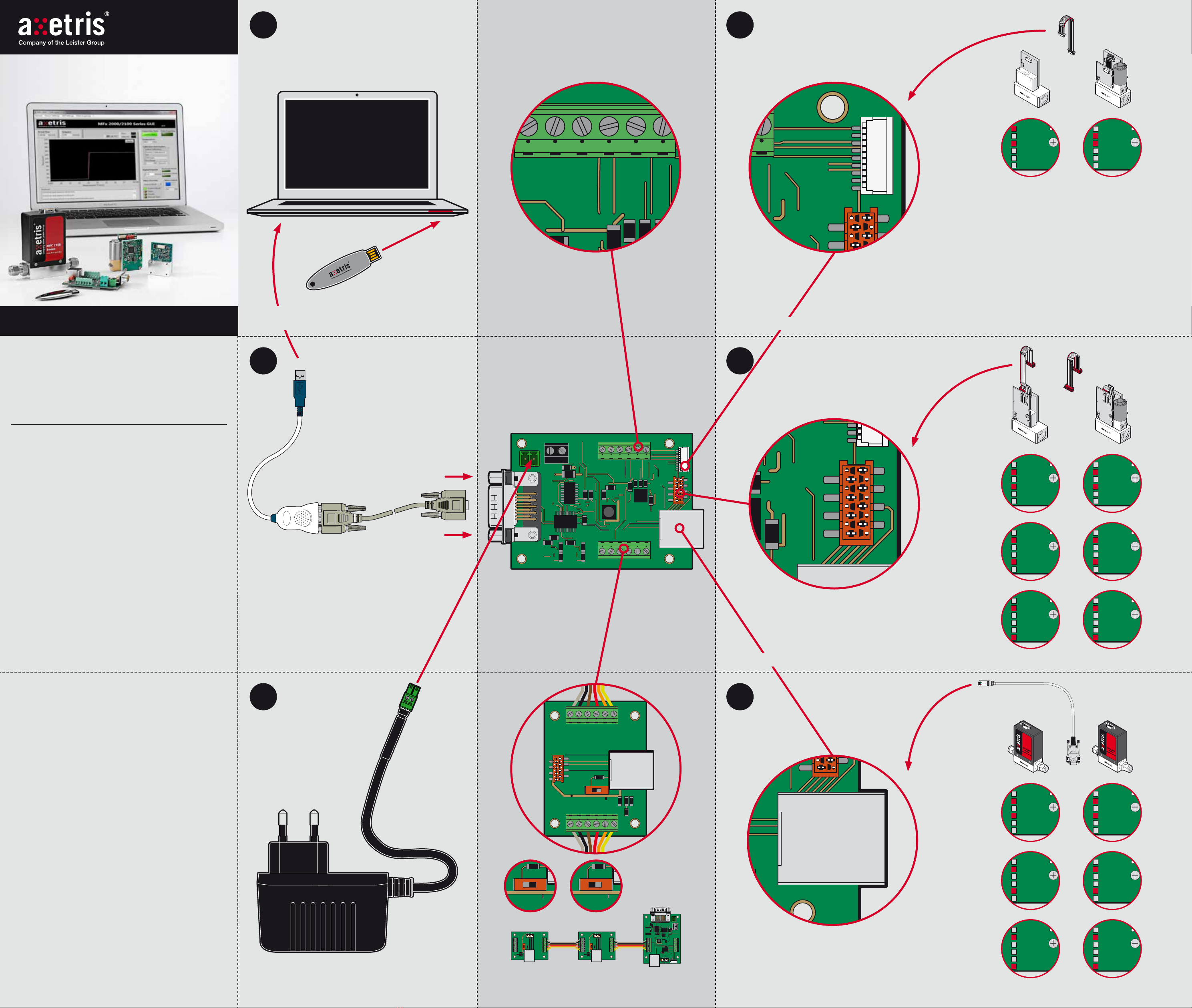
Introduction
Welcome to Axetris Mass Flow Meter and Controller LabKit for fast and
easy evaluation. LabKit interface boards are intended for OEM module
evaluation only and should not be used for commercial applications or
production equipment.
Getting started explains how to connect the Mass Flow Device with the
interface board and the computer. Please follow the instruction exactly.
Do not hesitate to contact your distributor or Axetris in case of questions.
Important
The meter modules MFM 2020 and MFM 2021 need a supply voltage of
12 V DC all other devices need 24 V DC. So it is important to connect the
devices as explained in this document. Failures may lead to a malfunction
or damage of the MFD device.
Features
The Graphical User Interface (GUI) allows digital communication to read
device information like type, serial number and calibration and to read and
write the settings of the MFD device. It allows to adjust the set point (con-
troller only) and to read flow and temperature values. In addition it offers
data logger functionality. For controllers you can select and define rectangular
set point curves over time, to study the dynamics. You can even define arbi-
trary curves to simulate the behaviour of your system as close as possible.
For further information please consult your manuals: “Instruction Manuals
LabKit for Axetris Mass Flow Meters & Controllers” or the “Quick Guide
MFx2000 / 2100 Series Graphical User Interface”. For information of
the device consult the datasheet, the installation manual or the operating
manual of your device.
The Axetris mass flow sensor
All the mass flow devices are based on the Axetris proprietary MEMS
technology. The anemometric mass flow chip sensor is based on platinum
technology, and offers exceptional performance in terms of accuracy,
speed, stability, responsiveness and life time.
Contact
Swiss Made Quality. Axetris is an ISO 9001 certified enterprise.
Specifications are subject to change without prior notice.
Getting started, LabKit for 2000 Series Mass Flow Meters & Controllers, Art. No 603.420
China:
Leister Technologies Ltd.
Building 11, 155 Yuanke Road
Xinzhuang Industry Park
Shanghai 201 109
China
phone: +86 21 6442 2398
fax: +86 21 6442 2338
axetris@axetris.cn
www.axetris.cn
Japan:
Leister Technologis KK
Shinyokohama Bousei Bldg 1F
3-20-12, Shinyokohama, Kohoku-ku
Yokohama 222-0033 / Japan
phone: +81 45 477 36 37
fax: +81 45 477 36 38
axetris@axetris.jp
www.axetris.jp
LabKit Y-Connector board with ON / Off switch
for RS-485 only
LabKit for Axetris Mass Flow Meters & Controllers /
Getting started
Getting started
LabKit for 2000 Series Mass Flow Meters
& Controllers
Power supply,
output voltage 24 VDC
MFM 2120
MFM 2220
MFM 2020
MFC 2122
MFC 2222
MFC 2022
MFM 2140
MFM 2240
MFC 2142
MFC 2242
MFM 2150
MFM 2250
MFC 2152
MFC 2252
Analog connector for
MFM 2020, MFC 2022
MFM 2220, MFC 2222
MFM 2120, MFC 2122
Interface board fronside
Interface board Frontside
Laptop with USB stick
for Software installation
USB conector / RS-232 cabel
Interface board Frontside
Interface board Frontside
2a
2c
1
3
4
2b
Interface board Backside
Interface board Backside
Interface board Backside


