AXIOMTEK iHPC300 User manual

iHPC300
4U Rackmount GPU Workstation
with Intel® Xeon® Scalable
Processor, supports multiple
accelerator Cards
User’s Manual

ii
Disclaimers
This manual has been carefully checked and believed to contain accurate information.
Axiomtek Co., Ltd. assumes no responsibility for any infringements of patents or any third
party’s rights, and any liability arising from such use.
Axiomtek does not warrant or assume any legal liability or responsibility for the accuracy,
completeness or usefulness of any information in this document. Axiomtek does not make any
commitment to update the information in this manual.
Axiomtek reserves the right to change or revise this document and/or product at any time
without notice.
No part of this document may be reproduced, stored in a retrieval system, or transmitted, in
any form or by any means, electronic, mechanical, photocopying, recording, or otherwise,
without the prior written permission of Axiomtek Co., Ltd.
CAUTION
Wrong type of batteries may cause explosion. It is recommended that users only replace with
the same or equivalent type of batteries as suggested by the manufacturer once properly
disposing of any used ones.
©Copyright 2021 Axiomtek Co., Ltd.
All Rights Reserved
August 2021, Version A1
Printed in Taiwan

iii
ESD Precautions
Computer boards have integrated circuits sensitive to static electricity. To prevent chipsets
from electrostatic discharge damage, please take care of the following jobs with precautions:
◼Do not remove boards or integrated circuits from their anti-static packaging until you are
ready to install them.
◼Before holding the board or integrated circuit, touch an unpainted portion of the system
unit chassis for a few seconds to discharge static electricity from your body.
◼When handling boards and components, wear a grounding wrist strap available from
most electronic component stores.
Trademarks Acknowledgments
Axiomtek is a trademark of Axiomtek Co., Ltd.
Intel®and Celeron®are trademarks of Intel Corporation.
Windows®is a trademark of Microsoft Corporation.
AMI is a trademark of American Megatrend Inc.
IBM, PC/AT, PS/2, and VGA are trademarks of International Business Machines Corporation.
Other brand names and trademarks are the properties and registered brands of their
respective owners.

iv
Table of Contents
Disclaimers ......................................................................................................ii
ESD Precautions............................................................................................. iii
Section 1 Introduction............................................. 1
1.1 Features ................................................................................................2
1.2 Specifications ........................................................................................2
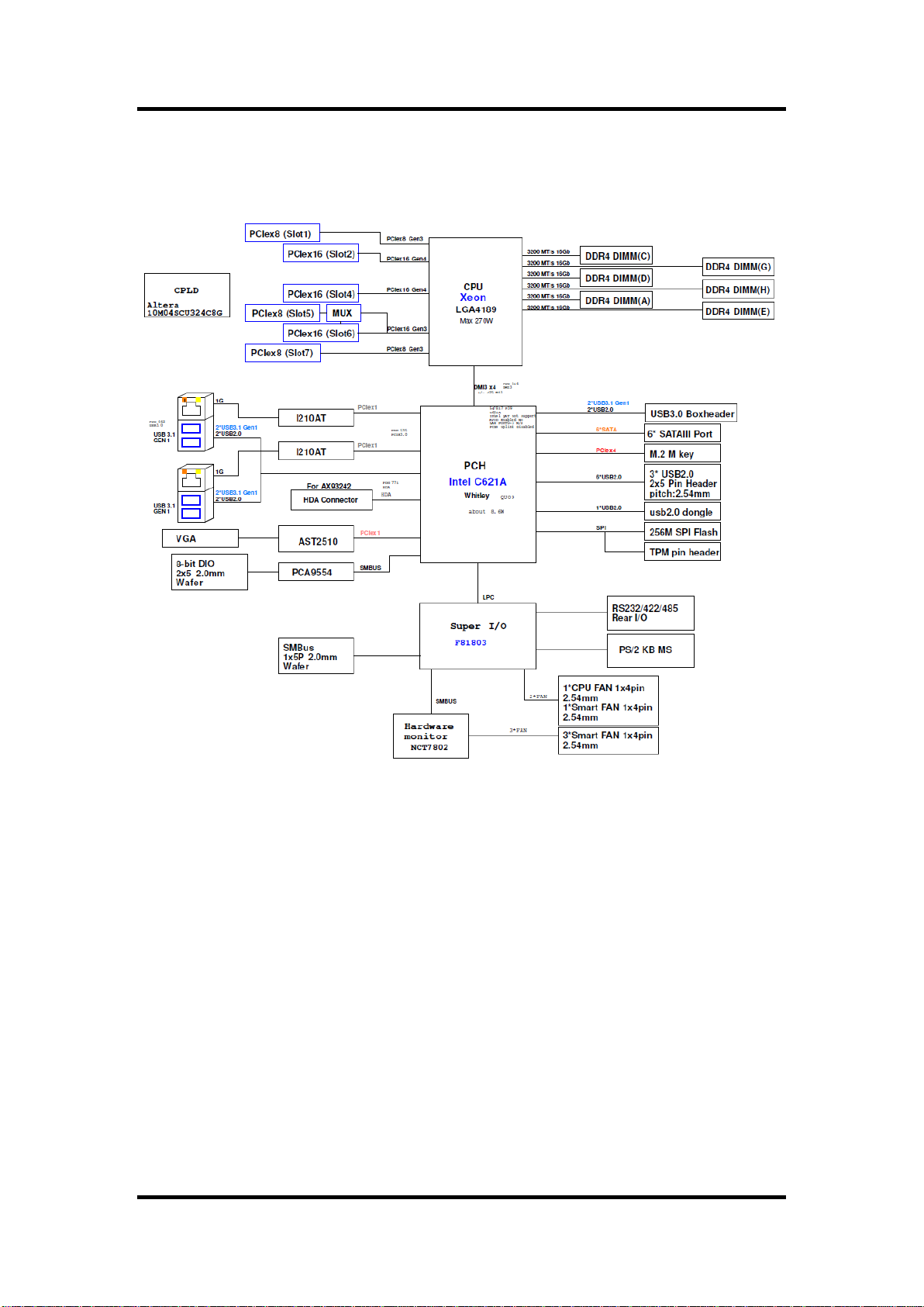
1.3 M/B Block Diagram & System Dimensions............................................4
1.4 Outlets & System Layout.......................................................................6
1.5 Packing list ............................................................................................7
1.6 Jumper Settings ....................................................................................8
1.6.1 Temperature Sensor Source Select (JP2)................................................... 9
1.6.2 PCIe x16 slot bifurcation (JP13) .................................................................. 9
1.6.3 Clear CMOS (JP19) .................................................................................... 9
1.6.4 AT/ATX Mode Select (JP20)...................................................................... 10
1.7 Connectors..........................................................................................11
1.7.1 VGA Connector (CN1)............................................................................... 12
1.7.2 LAN and USB 3.1 Connectors (CN3 and CN4) ........................................ 12
1.7.3 External Sensor Header (CN5) ................................................................... 12
1.7.4 GPIO Header (CN6) .................................................................................. 13
1.7.5 TPM Pin Header (CN11) ............................................................................. 13
1.7.6 M.2 2280 Key M PCIe x4 SSD slot (CN12) .............................................. 14
1.7.7 SMBus Header (CN14) ............................................................................. 14
1.7.8 Voltage Monitor Header (CN15)................................................................ 15
1.7.9 Front Panel Header (CN16) ...................................................................... 15
1.7.10 Power Input Connectors (ATX1, ATX2, CN18 and CN19) ........................ 16
1.7.11 Internal USB 3.1 Gen1 Connector (CN20)................................................ 17
1.7.12 COM1 Connector (COM1) ........................................................................ 17
1.7.13 Fan Connectors (FAN1~FAN3 and FAN5~6)............................................ 18
1.7.14 Internal USB Headers (USB1~4) .............................................................. 18
1.7.15 SATA 3.0 Connectors (SATA1 ~ SATA6)................................................... 19
1.7.16 LAN Active LED connectors (JP3 and JP10) ............................................ 19
1.7.17 Programmable LED connectors (JP4) ...................................................... 19
1.7.18 Keyboard and PS/2 Mouse Connector (PS1) ........................................... 19
1.7.19 Intel® HD Audio Digital Header (HDA1)..................................................... 20
Section 2 Hardware Installation ........................... 21
2.1 Installing the CPU...................................................................................... 21
2.2 Installing the Memory ................................................................................ 25
Section 3 AMI BIOS Setup Utility .......................... 27

v
3.1 Starting................................................................................................27
3.2 Navigation Keys ..................................................................................27
3.3 Main Menu ..........................................................................................29
3.4 Advanced Menu ..................................................................................30
3.5 Platform Configuration.........................................................................41
3.6 Socket Configuration...........................................................................46
3.7 Security Menu .....................................................................................49
3.8 Boot Menu...........................................................................................50
3.9 Save & Exit Menu................................................................................51
Appendix A Watchdog Timer .................................... 53
About Watchdog Timer...................................................................................53
How to Use Watchdog Timer .........................................................................53
Appendix B TPM Module Installation ....................... 55
Appendix C Configuring SATA for RAID.................... 59
Configuring SATA Hard Drive(s) for RAID Function .......................................59
Appendix D Digital I/O............................................... 65
Digital I/O Software Programming..................................................................65

vi
This page is intentionally left blank.

iHPC300 User Manual
Introduction 1
Section 1
Introduction
The iHPC300 is built on the LGA4189 socket Intel® Xeon® Scalable processor and provides
massive parallel computing power and networking flexibility with three PCIe x16 slots, three
PCIe x8 slots, and NVMe M.2 Key M 2280 interface with PCIe x4 signal, supporting up to six
accelerator cards (GPUs and high-speed NVMe storage). This reliable and efficient GPU
workstation also supports six SATA-600 ports with integrated RAID 0/1/5/10 for protection
against data loss. To offer a wide range of I/Os, the iHPC300 has six USB 3.1 Gen1 ports,
seven USB 2.0 ports, one RS-232/422/485 port, two GbE LAN ports with Intel® Ethernet
controller i210-AT, one VGA port, 8-channel programmable digital I/O port, one HD Codec
audio, SMBus, and one PS/2 keyboard and mouse. Trusted Platform Module 2.0 (TPM 2.0) is
also available as an optional feature to ensure critical information security. The iHPC300 can
operate under a wide temperature range from 0°C to +40°C. With increased computing power,
it is suitable for performing deep learning AI, video surveillance, industrial automation and
other diverse applications.”

iHPC300 User Manual
2 Introduction
1.1 Features
⚫LGA4189 socket Intel® Xeon® Processor Scalable, up to 270W, 40 cores
⚫Six DDR4-3200 R-DIMM un-buffered non-ECC/ECC memory, up to 384GB
⚫Expansion slots: 3 PCIe x16 and 3 PCIe x8, supporting up to three accelerator cards
⚫Supports M.2 Key M 2280
⚫TPM 2.0 supported (optional)
1.2 Specifications
⚫CPU
◼LGA4189 Socket Intel®Xeno®Scalable Ice Lake-SP processor up to 270W, 40 cores
⚫Chipset
◼Intel®C621A
⚫BIOS
◼AMI BIOS
⚫System Memory
➢6 x 288-pin DIMM sockets
➢Maximum 384GB DDR4 memory (max. 64GB per slot)
➢Supports 3200MHz
➢Supports the RDIMM un-buffered non-ECC/ ECC memory
⚫Drive Capacity
◼Exposed 3 x 5.25" HDD drive bay and 1 x 3.5" HDD drive bay
◼Internal 3 x 3.5" HDD drive bay or 2 x 3.5" or 1 x 2.5"
⚫Cooling
◼1 x 12 cm PWM front fan
◼2 x 8 cm easy-swap rear fan
⚫Front Panel
◼Indicator: 1 x power LED, 1 x HDD LED, 2 x LAN activity LED & 1 x programmable
LED
◼Controls: 1 x power switch & 1 x system reset
◼Connector: 2 x USB 3.1 Gen1
⚫Watchdog Timer
◼255 levels, 1 ~ 255 sec
⚫Onboard Rear I/O
◼1 x PS/2 keyboard and mouse
◼1 x RS-232/422/485 (BIOS selection)
⚫USB Interface
◼6 x USB3.1(Gen1) ports (4 x real I/O, 2 x internal box header)
◼7 x USB 2.0 ports (6 x internal box header, 1 x 180D TypeA)

iHPC300 User Manual
Introduction 3
⚫Ethernet
◼LAN1: 1000/100/10Mbps Gigabit/Fast Ethernet supports Wake-on-LAN, PXE Boot
ROM with Intel®i210-AT
◼LAN2: 1000/100/10Mbps Gigabit/Fast Ethernet supports Wake-on-LAN, PXE Boot
ROM with Intel®i210-AT
⚫Storage
◼6 x SATAIII with RAID 0/1/5/10
◼1 x M.2 M-Key 2280 with PCIe x4 signal for NVMe SSD
⚫Audio
◼Supports HD audio interface as a 2x8 pin header
◼Supports audio kit AX93242 with MIC-in/Line-in/Line-out/Speaker-out (optional kit)
⚫Display
◼1 x 15-pin D-Sub as VGA connector. Resolution max. up to 1920x1200 @60Hz
◼AST2510
⚫Expansion Interface
◼Slot 1: PCIe x8 (Gen3)
◼Slot 2: PCIe x16 (Gen4)
◼Slot 3: M.2 Key M 2280 (signal: x4)
◼Slot 4: PCIe x16 (Gen4)
◼Slot 5: PCIe x8 (signal: x0 or x8, Gen3)
◼Slot 6: PCIe x16 (signal: x16 or x8, Gen3)
◼Slot 7: PCIe x8 (Gen3)
Note
Default: slot 6 provides PCIe x16 signal, while slot 5 has no signal.
If you want to switch slot 5 and slot 6 signal to PCIe x8 signal, please refer
to section 2.4.2.
⚫SMBus
◼System Management Bus for advanced monitoring/control
⚫Digital I/O
◼8 channels programmable
⚫Power Supply Type (2 SKU: 1200W or 2000W PSU to choose from)
◼1200W: AC input voltage 100 to 240V
◼2000W: AC input voltage 200 to 240V
⚫Operating Temperature
◼0°C ~ 40°C (+32°F to +104°F)
⚫Storage Temperature
◼-20°C ~ 85°C (-4°F to +140°F)
⚫Operating Humidity
◼10% to 95% relative humidity, non-condensing
⚫Dimensions
◼430 mm (16.9") (W) x 174.8 mm (6.9") (H) x 515mm (20.3") (D)
Note
All specifications and images are subject to change without notice.

iHPC300 User Manual
4 Introduction
1.3 M/B Block Diagram & System Dimensions
The following figure shows you the M/B block diagram of iHPC300.

iHPC300 User Manual
Introduction 5
The following diagram shows you system dimensions.

iHPC300 User Manual
6 Introduction
1.4 Outlets & System Layout
The following figures shows you the outlets on the front panels of iHPC300.

iHPC300 User Manual
Introduction 7
1.5 Packing list
The package bundled with your iHPC300 should contain the following items:
⚫iHPC300 unit x 1
⚫CPU clip x 1
⚫Power cord x 1
⚫SATA cable x 2
If you cannot find this package or any items are missing, please contact Axiomtek distributors
immediately.

iHPC300 User Manual
8 Introduction
1.6 Jumper Settings
Pin description
A jumper is a small component consisting of a jumper clip and jumper pins. Install a jumper clip
on two jumper pins to close the jumper pins. Remove the jumper clip from two jumper pins to
open the jumper pins. The following illustration shows how to set up a jumper.
Before applying power to the iHPC300, make sure all of the jumpers are in factory default
position. Below you can find a summary table of all jumpers and onboard default settings.
Note
Turn off power before changing any default jumper settings.
Jumper
Description
Setting
JP2
System temperature sensor source select
Default: internal sensor
External sensor can be installed on 1-2
2-3 Close
JP13
PCIe x16 slot using location slot 5
Default: x16
1-2 Close
JP19
Clear CMOS
Default: Normal operation
1-2 Close
JP20
AT/ATX power mode select
Default: AT mode
1-2 Close
Note
To identify the first pin of a header or jumper, please refer to the following
information:
⚫Usually, there is a thick line or a triangle near the header or jumper pin 1.
⚫A square pad, which you can find on the back of the motherboard, is usually
used for pin 1.

iHPC300 User Manual
Introduction 9
1.6.1 Temperature Sensor Source Select (JP2)
Use these jumpers (3x1-pin p=2.54mm) to set temperature sensor source to operate
from an external sensor or in onboard mode.
Note
An external sensor can be installed at 1-2.
1.6.2 PCIe x16 slot bifurcation (JP13)
Use these jumpers (3x1-pin p=2.54mm) to set signal for slot location 5 and 6 used as
PCIe x16 slot.
Note
If the setting is 1-2 close, slot location 6 is for PCIe x16 signal and slot
location 5 has no signal.
If the setting is 2-3 close, slot location 6 is PCIe x8 signal and slot location
5 is PCIe x8.
1.6.3 Clear CMOS (JP19)
This jumper (3x1-pin p=2.54mm) allows you to clear the Real Time Clock (RTC) RAM in
CMOS. You can clear the CMOS memory of date, time, and system setup parameters
by erasing the CMOS RTC RAM data. The onboard button cell battery powers the RAM
data in CMOS, which includes system setup information such as system passwords.
To erase the RTC RAM:
1. Turn OFF the computer and unplug the power cord.
2. Remove the onboard battery.
3. Move the jumper clip from pins 1-2 (default) to pins 2-3. Keep the clip on pins 2-3
for about 5~10 seconds, then move the clip back to pins 1-2.
4. Re-install the battery.
5. Plug the power cord and turn ON the computer.
6. Hold down the <Del> key during the boot process and enter BIOS setup to re-enter
data.
Function
Setting
External Sensor (CN5)
1-2 close
Onboard Sensor (Default)
2-3 close
Function
Setting
X16 and no signal (Default)
1-2 close
X8 and X8
2-3 close
Function
Setting
Normal operation (Default)
1-2 close
Clear CMOS
2-3 close

iHPC300 User Manual
10 Introduction
1.6.4 AT/ATX Mode Select (JP20)
This 3x1-pin p=2.54mm jumper allows you to select AT or ATX power mode.
Function
Setting
AT mode (Default)
1-2 close
ATX mode
2-3 close

iHPC300 User Manual
Introduction 11
1.7 Connectors
Signals go to other parts of the system through connectors. Loose or improper connection
might cause problems, Make sure all connectors are properly and firmly connected. Here is a
summary table showing the connectors on the hardware.
Connector
Description
CN1
VGA Connector
CN3
LAN + USB3.1 GEN1 Connector
CN4
LAN + USB3.1 GEN1 Connector
CN5
External Sensor Header
CN6
GPIO Connector
CN11
TPM 2.0 Connector (Optional)
CN12
M.2 Connector
CN14
SMBus Header
CN15
Voltage Monitor Header
CN16
Front Panel Header
CN18
24-pin ATX Power Input Connector
CN20
Internal USB3.1 GEN1 Connector
ATX1
ATX 12V Power Input Connector
ATX2, CN19
CPU Power Input Connector
COM1
COM port Connector
FAN1~3, FAN6
System Fan Connectors
FAN5
CPU Fan Connector
USB1
Internal USB2.0 Type A Connector
USB2
Internal USB2.0 Headers
USB3
Internal USB2.0 Headers
USB4
Internal USB2.0 Headers
Slot1,Slot5,Slot7
PCI-Express x8 Slots (Gen3)
Slot2,Slot4
PCI-Express x16 Slots (Gen4)
Slot6
PCI-Express x16 Slots (Gen3)
SATA1~SATA6
SATA III Connector
JP3
LAN1 Active LED Connector
JP10
LAN2 Active LED Connector
JP4
Programmable LED Connector
PS1
PS/2 Connector
HDA1
Audio Connector for AX93242
DIMM1~DIMM6
DDR4 RDIMM Connector

iHPC300 User Manual
12 Introduction
LAN
USB
1.7.1 VGA Connector (CN1)
The 15-pin D-Sub connector is commonly used for VGA display.
1.7.2 LAN and USB 3.1 Connectors (CN3 and CN4)
The motherboard comes with two high performance plug and play Ethernet interfaces
(RJ-45) which are fully compliant with the IEEE 802.3 standard. Connection can be
established by plugging one end of the Ethernet cable into this RJ-45 connector and the
other end to a 1000/100/10 Base-T hub.
The Universal Serial Bus (compliant with USB 3.1 Gen2 (CN3) or USB3.1 Gen1 (CN4))
connectors on the rear I/O are used for installing USB peripherals such as a keyboard,
mouse, scanner, etc.
1.7.3 External Sensor Header (CN5)
The external sensor header is an 1x2-pin p=2.54mm header. The function of CN5 is to
connect an external sensor.
Pin
Signal
Pin
Signal
1
Red
2
Green
3
Blue
4
NC
5
GND
6
GND
7
GND
8
GND
9
VCC
10
GND
11
NC
12
DDC DATA
13
Horizontal Sync
14
Vertical Sync
15
DDC CLK
Pin
LAN Signal
Pin
LAN Signal
L1
Tx+ (Data
transmission positive)
L2
Tx- (Data transmission
negative)
L3
Rx+ (Data reception
positive)
L4
RJ-1 (For 1000 Base-T
only)
L5
RJ-1 (For 1000
Base-T only)
L6
Rx- (Data reception
negative)
L7
RJ-1 (For 1000
Base-T only)
L8
RJ-1 (For 1000 Base-T
only)
A
100 LAN LED (Green)
/ 1000 LAN LED
(Orange)
B
Active LED
Pin
Signal
1
Sys_Temp
2
GND

iHPC300 User Manual
Introduction 13
1.7.4 GPIO Header (CN6)
This header (5x2-pin p=2.00mm) is for digital I/O interface.
Note
The default value of DIO1 to DIO8 is set as GPI with high level.
1.7.5 TPM Pin Header (CN11)
These are 7x2-pin p=2.0mm headers for SPI interface with an AX93515 TPM module.
Note
The screw type is M2*0.4.
Pin
Signal
Pin
Signal
1
DIO1
2
DIO8
3
DIO2
4
DIO7
5
DIO3
6
DIO6
7
DIO4
8
DIO5
9
NC
10
GND
Pin
Signal
Pin
Signal
1
VCC3P3
2
GND
3
MOSI
4
MISO
5
CLK
6
CS2
7
RST
8
PIRQ
9
PP
10
NC
11
NC
12
NC
13
NC
14
MC
13 11 9 7 5 3 1
14 12 10 8 6 4 2

iHPC300 User Manual
14 Introduction
1.7.6 M.2 2280 Key M PCIe x4 SSD slot (CN12)
The iHPC300 comes with one M.2 2280 Key M slot with PCIe x4 signal for NVMe SSD
storage.
Pin
Signal
Pin
Signal
Pin
Signal
Pin
Signal
1
GND
2
+3.3V
3
GND
4
+3.3V
5
PEX3_RX-
6
NC
7
PEX3_RX+
8
NC
9
GND
10
LED_1#
11
PEX3_TX-
12
+3.3V
13
PEX3_TX+
14
+3.3V
15
GND
16
+3.3V
17
PEX2_RX-
18
+3.3V
19
PEX2_RX+
20
NC
21
GND
22
NC
23
PEX2_TX-
24
NC
25
PEX2_TX+
26
NC
27
GND
28
NC
29
PEX1_RX-
30
NC
31
PEX1_RX+
32
NC
33
GND
34
NC
35
PEX1_TX-
36
NC
37
PEX1_TX+
38
M.2_DEVSLP
39
GND
40
NC
41
PEX0_RX-
42
NC
43
PEX0_RX+
44
NC
45
GND
46
NC
47
PEX0_TX-
48
NC
49
PEX0_TX+
50
PERST#
51
GND
52
CLKREQ#
53
PEX0_REFCLKn
54
PEWAKE#
55
PEX0_REFCLKp
56
NC
57
GND
58
NC
59
CONNECTOR
Key M
60
CONNECTOR
Key M
61
CONNECTOR
Key M
62
CONNECTOR
Key M
63
CONNECTOR
Key M
64
CONNECTOR
Key M
65
CONNECTOR Key
M
66
CONNECTOR Key
M
67
NC
68
NC
69
NC
70
+3.3V
71
GND
72
+3.3V
73
GND
74
+3.3V
75
GND
1.7.7 SMBus Header (CN14)
The CN14 (5x1-pin p=2.00mm) is for SMBus (System Management Bus) interface.
Pin
Signal
Pin
Signal
1
SMB_SCL
2
N/C
3
GND
4
SMB_SDA
5
+5V
Table of contents