manuals.online logo
Brands
  1. Home
  2. •
  3. Brands
  4. •
  5. Azbil
  6. •
  7. Humidistat
  8. •
  9. Azbil Neostat HY9000Z User manual

Azbil Neostat HY9000Z User manual

This manual suits for next models

2

Popular Humidistat manuals by other brands

GeneralAire M3 owner's manual

GeneralAire

GeneralAire M3 owner's manual

MS Electronics E914 Product guide

MS Electronics

MS Electronics E914 Product guide

Boneco A7056 Instructions for use

Boneco

Boneco A7056 Instructions for use

Regin TRT50 instruction manual

Regin

Regin TRT50 instruction manual

Vector TCY-BH-U operating instructions

Vector

Vector TCY-BH-U operating instructions

MS Electronics IP65H Product guide

MS Electronics

MS Electronics IP65H Product guide

Nordmann HSN installation instructions

Nordmann

Nordmann HSN installation instructions

GeneralAire E2 Installation and owner's manual

GeneralAire

GeneralAire E2 Installation and owner's manual

Condair 2520273 installation instructions

Condair

Condair 2520273 installation instructions

Vemer HUMI user manual

Vemer

Vemer HUMI user manual

Honeywell H8908A/B installation instructions

Honeywell

Honeywell H8908A/B installation instructions

Regin ED-RUD-2 Series instructions

Regin

Regin ED-RUD-2 Series instructions

Regin HR1 instructions

Regin

Regin HR1 instructions

Skuttle Indoor Air Quality Products SK0-0055-001 installation instructions

Skuttle Indoor Air Quality Products

Skuttle Indoor Air Quality Products SK0-0055-001 installation instructions

Neptronic HRO20 Specification & installation instructions

Neptronic

Neptronic HRO20 Specification & installation instructions

Lucky Reptile Humidity Control II operating instructions

Lucky Reptile

Lucky Reptile Humidity Control II operating instructions

Honeywell H8908B Humidistat installation instructions

Honeywell

Honeywell H8908B Humidistat installation instructions

General Filters MHX3C installation manual

General Filters

General Filters MHX3C installation manual

manuals.online logo
manuals.online logoBrands
  • About & Mission
  • Contact us
  • Privacy Policy
  • Terms and Conditions

Copyright 2025 Manuals.Online. All Rights Reserved.

AB-7259
1
Specifications/Instructions
Neostat
Room Humidistat (Proportional Type)
General
Neostat Model HY9000Z is an electric room humidistat that is
similar in design and size to Neosensor, the electronic room
temperature or humidity sensor.
A moisture-sensitive nylon ribbon is adopted for the
humidistat.
Features
●Simple connection to our actuator allows easy humidity
control.
●Compact (thin) and lightweight.
●Several installation types selectable in combination with
optional auxiliary devices.
Model Numbers
Model number Control action Range Our corporate logo (on the cover)
HY9000Z8000 Printed
HY9000Z8000-1
Proportional* 30 %RH to 80 %RH
Not printed
Note:
* Use Neostat (proportional type) with our Control Motor or ACTIVAL™.
AB-7259
2
Safety Instructions
Please read instructions carefully and use the product as specified in this manual. Be sure to keep this manual near by for ready
reference.
Usage Restrictions
This product is targeted for general air conditioning. Do not use this product in a situation where human life may be affected. If
this product is used in a clean room or a place where reliability or control accuracy is particularly required, please contact our
sales representative. Azbil Corporation will not bear any responsibility for the results produced by the operators.
Warnings and Cautions
WARNING Alerts users that improper handling may cause death or serious injury.
CAUTION Alerts users that improper handling may cause minor injury or material loss.
Signs
Alerts users possible hazardous conditions caused by erroneous operation or erroneous use. The symbol inside 
indicates the specific type of danger.
(For example, the sign on the left warns of the risk of electric shock.)
Notifies users that specific actions are prohibited to prevent possible danger. The symbol inside graphically
indicates the prohibited action.
(For example, the sign on the left notifies that disassembly is prohibited.)
Instructs users to carry out a specific obligatory action to prevent possible danger. The symbol inside graphically
indicates the actual action to be carried out.
(For example, the sign on the left indicates general instructions.)
CAUTION
Use the product under the operating conditions (temperature, humidity, power, vibration, shock, mounting direction,
atmospheric condition, etc.) as listed in the specifications.
Failure to do so might cause fire or device failure.
Use the product within the rated operating ranges as listed in the specifications.
Failure to do so might cause device failure.
Installation and wiring must be performed by qualified personnel in accordance with all applicable safety standards.
All wiring must comply with applicable codes and ordinances.
Before wiring, be sure to turn off the power to the product.
Failure to do so might cause electric shock.
To connect the wires to the screw terminals, use crimp terminal lugs with insulation.
Failure to do so might cause fire or device failure due to short circuit.
Do not disassemble the product.
Doing so might cause electric shock or device failure.
Dispose of the product as industrial waste in accordance with your local regulations.
Do not reuse all or part of this product.
AB-7259
3
Part Numbers of Optional Items
Mount Neostat with the following optional items (sold separately). Order necessary items.
Item Part number/Model number Note
Wall-direct mounting kit Part No. 83165803-001 —
Thermoplate mounting kit Part No. 83165803-011 —
Dedicated mounting kit
Multi-Thermocase mounting kit Part No. 83165803-021 —
Model QY1100A With slide switch
Model QY1100C
Thermoplate for individual room
control
Model QY1100D
With rotary switch
Part No. DY2000A1022 For mounting one Neostat, lengthwise
Part No. DY2000A1023 For mounting one Neostat, crosswise
Part No. DY2000A2023 For mounting two Neostat in
94mm (H) x 192mm (W) outlet box, crosswise
Part No. DY2000A2024 For mounting two Neostat in
106mm (H) x 198mm (W) outlet box, crosswise
Thermoplate
Part No. DY2000A3022 For mounting three Neostat, crosswise
Part No. DY2000A1021 For mounting one Neostat, square
Part No. DY2000A2021 For mounting two Neostat, crosswise
Thermoplate for open wiring
* Thermoplate for open wiring
is used for open wiring
installation.
Part No. DY2000A3021 For mounting three Neostat, crosswise
Auxiliary device
Multi-Thermocase Model TY1100Z —
Dedicated mounting kits for each mounting method
Mounting method Mounting kit Contents
Mounting directly on a
wall
Mounting onto
Thermoplate for open
wiring
Wall-direct mounting kit
(Part No. 83165803-001)
Mounting onto
Thermoplate
Thermoplate mounting kit
(Part No. 83165803-011)
Mounting in
Multi-Thermocase
Multi-Thermocase mounting kit
(Part No. 83165803-021)
One flat-head machine
screw (M3 ×16)
Main unit
Mounting plate
Two pan-head machine screw (M4
×
8)
Man unit
Two tapping screws (M2.6
×
8)
Main unit
66.7 mm
Mounting screws are supplied with
the Multi-Thermocase (optional).
AB-7259
4
Specifications
Item Specification
Proportional bands Approx. 12 %RH fixed (at 50 %RH)
Sensing element Nylon ribbon
Power supply 24 V AC -15/+10 % (50 Hz/60 Hz)
Environmental conditions Rated operating conditions Transport/storage conditions
Ambient temperature 15 °C to 40 °C -20 °C to 50 °C
Ambient humidity 10 %RH to 95 %RH (non-condensing) Max. 95 %RH (non-condensing)
Color Pale gray
Cover PC resinMaterials
Base Modified PPE resin
Weight Approx. 190 g
Installation With the optional mounting kit (sold separately)
Connection Lead wire connection
Accessory Four mounting screws (M3 x 16)
PPE: Polyphenylene ether
Dimensions
Neostat with Wall-direct mounting kit
Note:
* Secure more than 15 mm clearance inside the mounting wall when installing Neostat with Wall-direct mounting kit.
Figure 1. Mounting dimensions (mm): Neostat with Wall-direct mounting kit
Mounting plate
Note:
* Use JIS outlet box/box cover (JIS C8340:1999) with 66.7 mm mounting dimension.
JIS: Japanese Industrial Standards
Figure 2. Dimensions (mm): Mounting plate of Wall-direct mounting kit
Connectors for connection check
Wall-direct
mounting kit
90
77
77
90
77
38.5
16.5
15*
Mounting
surface
Heat sink
77
80
66.7*
80
Mounting screw (M3)
⌀4.2 mounting hole Mounting hole
4.2
AB-7259
5
Neostat with Thermoplate mounting kit
Note:
* Secure more than 12.5 mm clearance from the Thermoplate surface to the inside of the mounting wall when installing Neostat with
Thermoplate mounting kit.
Figure 3. Mounting dimensions (mm): Neostat with Thermoplate mounting kit on Thermoplate
Thermoplate mounting kit
Figure 4. Dimensions (mm): Mounting plate of Thermoplate mounting kit
8
49
22
⌀2.8 mounting hole
77
77
77
Mounting
surface
41
19
12.5*
77
Connectors for connection check
Thermoplate mounting kit
Thermoplate
(optional)
Heat sink
Thermoplate mounting kit
AB-7259
6
Neostat (without the cover) with Multi-Thermocase mounting kit (to mount in Multi-Thermocase)
When installing Neostat in the optional Multi-Thermocase, remove the cover of Neostat.
Figure 5. Mounting dimensions (mm): Neostat (not covered) with Multi-Thermocase mounting kit
Multi-Thermocase mounting kit
Note:
* Assembling dimension with device mounting plate of Multi-Thermocase is 66.7 mm.
Figure 6. Dimensions (mm): Multi-Thermocase mounting kit
72.8
85
85
72.8
72.8
85
52
23
72.8
Multi-Thermocase
mounting kit
55
66.7*
68
⌀3.4 mounting hole
AB-7259
7
Installation
CAUTION
Use the product under the operating conditions (temperature, humidity, power, vibration, shock, mounting direction,
atmospheric condition, etc.) as listed in the specifications.
Failure to do so might cause fire or device failure.
Installation and wiring must be performed by qualified personnel in accordance with all applicable safety standards.
Requirements for installation location
IMPORTANT:
●Installation location of Neostat largely affects humidity control. Carefully select the location.
●Ask our salesperson for use of Neostat in a special application, as mentioned below.
- Chemical (organic solvent) atmosphere may shift the output values.
- Corrosive gas, organic solvent, and other chemicals contained in the atmosphere can cause measuring
error of Neostat, shorten the service life of Neostat, or damage Neostat.
●Do not tighten or loosen the screws (except the screws described in the Installation steps sections). Doing so
might damage Neostat.
Install Neostat on an indoor wall where:
●Representative temperature/humidity (of the room/zone to control) can be measured (approx. 1.5 m high above the floor)).
●Ambient wind velocity is 0.1 to 0.15 m/s.
●There is enough maintenance space left in front of Neostat.
Do not install Neostat on a wall where:
●Heat (generated by office device or equipment, for example) stays on.
●Air circulation is interfered (by furniture or door, for example).
●Humidity sensing is affected by draft, downdraft, and hot/cold air from water pipes/ducts.
●Humidity sensing is affected by weather conditions (including sunlight and outdoor air).
●There is vibration.
●Dew condensation occurs.
●Water drops on.
●Atmosphere that contains corrosive gas, organic solvent, or other chemicals surrounds.
Do not install Neostat outdoors or in a duct.
Do not install Neostat directly or horizontally on a ceiling.
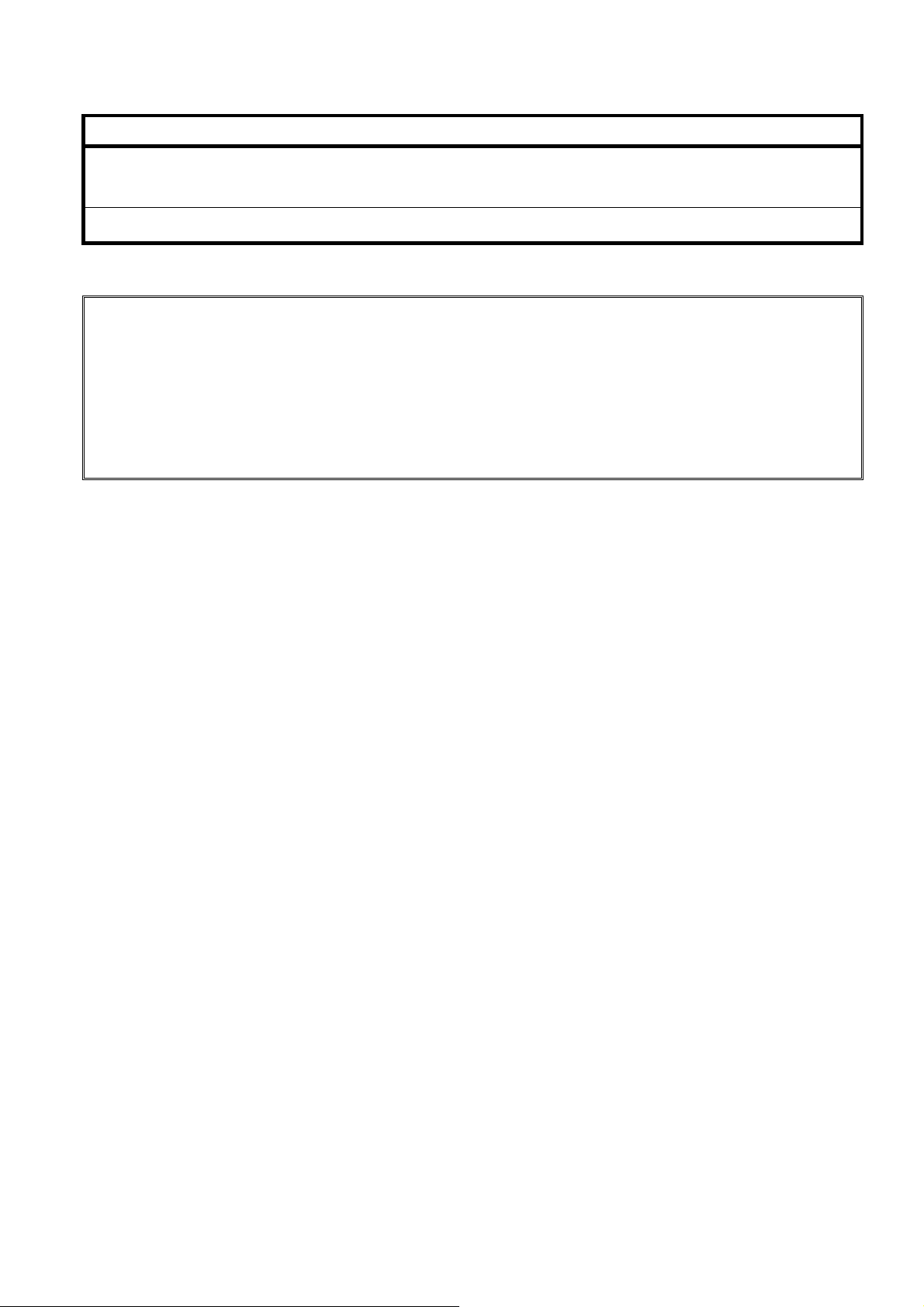
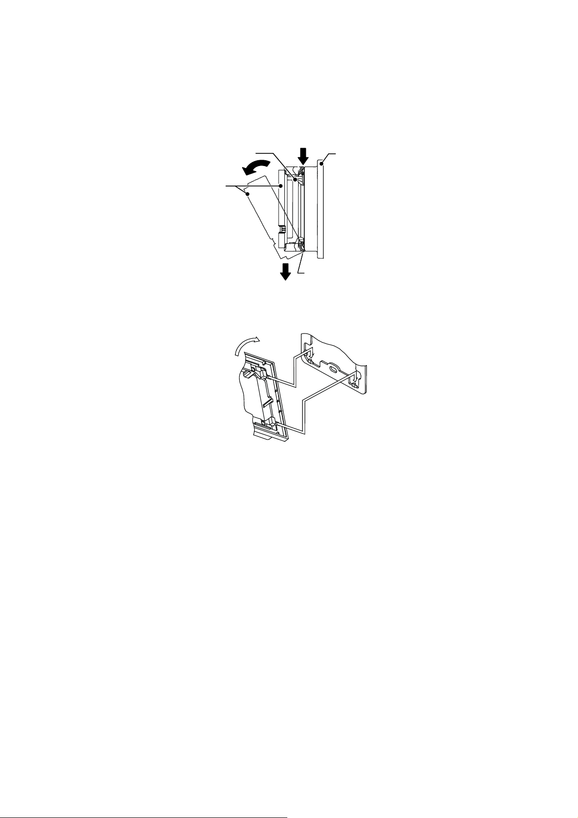
Precautions for installation
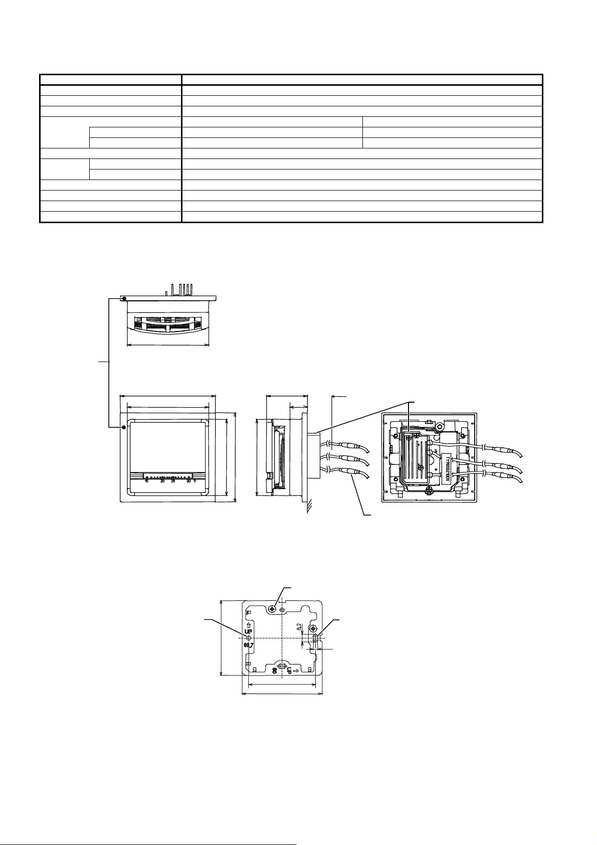
●Secure the clearance for wiring inside the wall (as shown in Figs. 1 and 3).
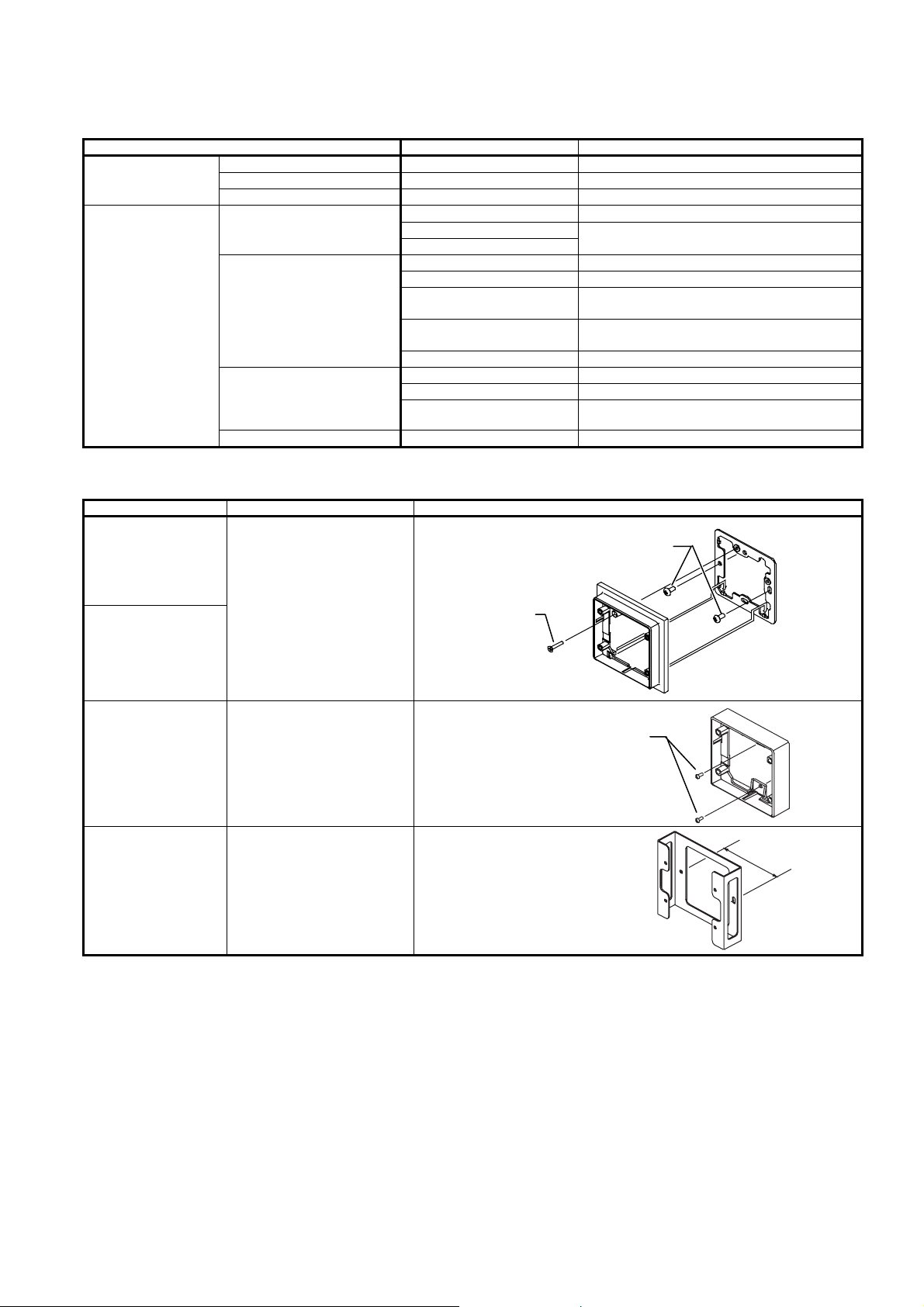
●Install Neostat with the optional dedicated mounting kit (sold separately) suitable for your application.
●Do not allow any refuse such as an electric wire scrap to get inside Neostat.
●Do not allow the lead wires caught between the mounting surface of Neostat and the wall.
●Do not put heavy load on the heat sink, the lead wires, etc. Doing so may distort Neostat, causing failure or affecting
humidity control.
●If air infiltrates to the rear side of the Neostat from the inside of the installed wall through the outlet box, shut off the air by
sealing the outlet box.
●After installation, leave Neostat well so that it adapts to ambient conditions (atmospheric environment).
AB-7259
8
Cover removal
To remove the cover:
Press the spring, located on the upper center part of the Neostat main unit, using a thin object.
To attach the cover:
Engage the tabs, located on the lower part of the cover, with the slots on the lower part of the main unit. Then fix the cover with
the spring, located on the upper center part of the Neostat main unit.
Figure 7. Cover removal
Assembling the Wall-direct mounting kit (the main unit to the mounting plate)
Figure 8. Assembling the Wall-direct mounting kit
Engage.
Mounting plate
Rear side of the main unit
A
ttach.
3. Disengage the tabs.
Wall-direct mounting kit
Cover
1. Press the spring.
Main unit
Tab of the cover
(at 2 locations)
2. Release the top o
f
the cover.
AB-7259
9
Installation steps: Neostat directly on a wall with Wall-direct mounting kit
1) Attach the mounting plate of the Wall-direct mounting kit to the outlet box cover (JIS C8340:1999 Boxes and box covers for
rigid metal conduits (mounting dimension: 66.7 mm)) on the mounting surface with tow pan-head machine screws (M4 x 8)
supplied with Wall-direct mounting kit.
2) Attach the main unit of the Wall-direct mounting kit to the mounting plate with one flat-head machine screw supplied with
Wall-direct mounting kit. (See Fig. 8.)
3) Connect the lead wires of Neostat and the wires from the load. (See Fig. 18.)
4) Remove the cover of Neostat. (See the Cover removal section.)
5) Set the depth change levers on the bilateral sides of the Neostat main unit to the upper position (indicated with "L" shown in
Fig. 15).
6) Mount the main unit of Neostat on the main unit of the Wall-direct mounting kit with four flat-head machine screws (M3 x 16)
supplied with Neostat.
7) Attach the cover back to the Neostat main unit. (See the Cover removal section.)
Figure 9. Installation: Neostat with Wall-direct mounting kit
66.7 mm
Wires
from the load
Mounting plate
of Wall-direct mounting kit
2 pan-head machine screws (M4
×
8)
of Wall-direct mounting kit
Main unit
of Wall-direct mounting kit
Lead wires of Neostat
1 flat-head machine screw
of Wall-direct mounting kit
Main unit of Neostat
4 flat-head machine screws
(M3 ×16) of Neostat
Cover of Neostat
Neostat Wall-direct mounting kit
(sold separately)
Outlet box cover (JIS C8340
with 66.7 mm mounting dimension,
commercially available)
AB-7259
10
Installation steps: Neostat on Thermoplate for open wiring with Wall-direct mounting kit
1) Attach the mounting plate of the Wall-direct mounting kit to the Thermoplate for open wiring on the mounting surface with
two pan-head machine screws (M4 x 8) supplied with Wall-direct mounting kit.
2) Attach the main unit of Wall-direct mounting kit to the mounting plate with one flat-head machine screw (M3 x 16) supplied
with Wall-direct mounting kit. (See Fig. 8.)
3) Connect the lead wires of Neostat to the wires from the load. (See Fig. 18.)
4) Remove the cover of Neostat. (See the Cover removal section.)
5) Set the depth change levers on the bilateral sides of the Neostat main unit to the upper position (indicated with "L" shown in
Fig. 15).
6) Mount the main unit of Neostat on the main unit of the Wall-direct mounting kit with four flat-head machine screws (M3 x 16)
supplied with Neostat.
7) Attach the cover back to the Neostat main unit. (See the Cover removal section.)
Figure 10. Installation: Neostat with Wall-direct mounting kit (on Thermoplate for open wiring)
Neostat Wall-direct mounting kit
(sold separately)
Thermoplate for open wiring
(Wires not led inside the wall,
sold separately)
66.7 mm
Wires
from the load
Mounting plate
of Wall-direct mounting kit
2 pan-head machine screws (M4
×
8)
of Wall-direct mounting kit
Main unit
of Wall-direct mounting kit
Lead wires of Neostat
1 flat-head machine screw
of Wall-direct mounting kit
Main unit of Neostat
4 flat-head machine screws
(M3 ×16) of Neostat
Cover of Neostat