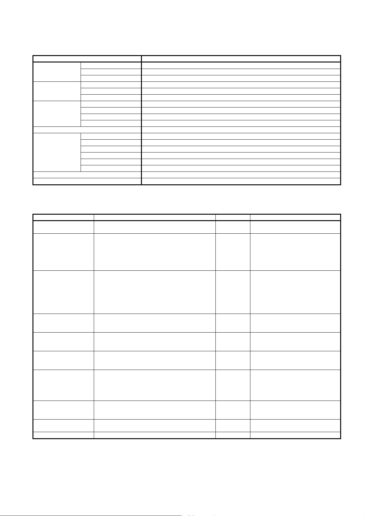
Azbil WY7208W Series User manual

AB-5702
1
Specifications/Instructions
Compact Data Gathering Panel
General
Compact Data Gathering Panel (often abbreviated as CDGP)
Model WY7208W is a terminal transmission device for
status/alarm monitoring, ON/OFF operation, and
measurement/metering of equipment installed in commercial
and other buildings.
One CDGP manages a small number of inputs/outputs (two
to eight points), and its compact body fits inside the building
distribution panel/power control panel. CDGP is thus
suitable for a small- and mid-sized building where the points
to monitor are decentralized.
Features
●Economical:
Price per point is substantially reduced compared to the
price per point of our former remote stations.
●Compact:
No additional remote panel is required to install CDGP at
remote locations. You can use available space in the
distribution panel or power panel.
●Simple wiring:
LAN cable is used for the communication line SC-bus.
Its modular connection facilitates wiring and also
minimizes misconnection.
●Easy setting:
Besides addressing with the rotary switch and functional
setting with the DIP switch, no other setting is required
for setup.
Model Numbers
Model number Description
WY7208W1120 DIO model (Select from the following point configurations using the DIP switch.)
- Start/stop point (maintained contact output) x 2
- Starts/stop, status point (maintained contact output) x 2
- Start/stop, status point (momentary contact output, without unmatched alarm monitoring) x 2
- Start/stop, status point (momentary contact output, with unmatched alarm monitoring) x 2
- Start/stop, status, alarm point (maintained contact output) x 2
- Start/stop, status, alarm point (momentary contact output, without unmatched alarm monitoring) x 2
- Start/stop, status, alarm point (momentary contact output, with unmatched alarm monitoring) x 2
WY7208W2180 DI model (Select from the following functions using the DIP switch.)
- Status, alarm point x 4
- Status point x 8
- Alarm point x 8
- Status point x 4 + alarm point x 4
WY7208W3180 TOT model (totalizer pulse input x 8)
WY7208W4140 AI model (1–5 V DC input or 4–20 mA DC input x 4)
WY7208W5140 RRD model (remote control relay drive output x 4)
WY7208W6140 Pt model (Pt100 input x 4)
Measuring range: -20 °C to 80 °C * This model is connectable to SmartScreen™ / Infilex™ ZM.

AB-5702
2
Safety Instructions
Please read instructions carefully and use the product as specified in this manual. Be sure to keep this manual near by for ready
reference.
Usage Restrictions
This product is targeted for general air conditioning. Do not use this product in a situation where human life may be affected. If
this product is used in a clean room or a place where reliability or control accuracy is particularly required, please contact our
sales representative. Azbil Corporation will not bear any responsibility for the results produced by the operators.
Warnings and Cautions
WARNING Alerts users that improper handling may cause death or serious injury.
CAUTION Alerts users that improper handling may cause minor injury or material loss.
Signs
Alerts users possible hazardous conditions caused by erroneous operation or erroneous use. The symbol inside
indicates the specific type of danger.
(For example, the sign on the left warns of the risk of electric shock.)
Notifies users that specific actions are prohibited to prevent possible danger. The symbol inside graphically
indicates the prohibited action.
(For example, the sign on the left notifies that disassembly is prohibited.)
Instructs users to carry out a specific obligatory action to prevent possible danger. The symbol inside graphically
indicates the actual action to be carried out.
(For example, the sign on the left indicates general instructions.)
WARNING
Be sure to ground the product with ground resistance of less than 100 Ω.
Improper grounding might cause electric shock or malfunction.
Before detaching the terminal cover, be sure to turn off the power to the product. After wiring, be sure to reattach the
terminal cover.
Failure to do so might cause electric shock.
Before wiring and maintenance, be sure to turn off the power to the product.
Failure to do so might cause electric shock or device failure.
Install this product in a location out of reach of unauthorized people. (e.g. Inside of the control panel)
Failure to do so might cause electric shock.
CAUTION (1/2)
Install and use the product in a location that meets the operating conditions (temperature, humidity, power, vibration,
shock, mounting direction, atmospheric condition, etc.) as listed in the specifications.
Failure to do so might cause fire or device failure.
Installation and wiring must be performed by qualified personnel in accordance with all applicable safety standards.
All wiring must comply with applicable codes and ordinances.
Take anti-lightning measures based on regional and building characteristics.
Lightning might cause fire or critical damage to the products without the anti-lightning measures.
Be sure to provide a circuit breaker for the power to the product as the product does not have a power switch.
To connect the wires to the screw terminals, use crimp terminal lugs with insulation.
Failure to do so might cause short circuit that leads to fire or device failure.
Firmly tighten the terminal screws.
Insufficient tightening of the terminal screws might cause fire or overheating.

AB-5702
3
CAUTION (2/2)
Do not use unused/spare terminals on the product as relay terminals.
Doing so might cause malfunction.
If more than the rated power voltage is applied to the product, replace the product with new one for your safety.
Failure to do so might cause fire.
Do not disassemble the product.
Doing so might cause device failure.
When replacing the battery, read the instructions hereinafter and correctly attach the new battery to the product.
Failure to do so might cause overheating, burst, or leakage of the battery.
Dispose of the used battery in accordance with your local regulations.
Do not throw it in fire or in general garbage.
Doing so might cause burst or ignition.
Dispose of this product as industrial waste in accordance with your local regulations. Do not reuse all or a part of this
product.

AB-5702
4
System Configurations
CDGP for BMS
For BMS and devices that are compatible to CDGP, ask our salesperson.
For AI and Pt models of CDGP, up to 20 CDGP are connectable to Infilex ZM via SC-bus.
CDGP for a simple system
Figure 1. System configuration examples
IMPORTANT:
To prevent fire, electric shock, injury, or other damage in the event that this product fails, the customer's
system should provide foolproof, fail-safe, and safety design that includes countermeasures to the spread of
fire and ensures the required degree of reliability and safety.
Web browser
in your PC
SC-bus (Max. 99 units and 1000 m)
CDGP
DIO/DI/RRD model
Model WY7208W1120/
WY7208W2180/WY7208W5140
Chiller plant equip.
/Plumbing equip.
/Lighting equip.
SmartScreen™
Ethernet
SmartScreen
dedicated LAN,
general office
purpose LAN
CDGP
AI/Pt/TOT model
Model WY7208W4140/
WY7208W6140/WY7208W3180
Sensor/
Meter
Infilex
™
FC
Model WY5205W8000/
WY5205W9000
FCU
User terminal
Model QY7205/QY7290
FCU: Fan coil unit
Other connectable devices to NC-bus:
DIF-II/Energy meter
Infilex™GC
Model WY5111
Infilex
™
GD
Model WY5110
NC-bus (Max. 25 units and 500 m, but extendable up to 1000 m with the repeater module.)
SC-bus (Max. 50 units and 1000 m)
CDGP
DIO model
Infilex
™
ZM
Model WY5122
DDC controller
for FCU
Infilex™ZM
Model WY5122
CDGP
DI model
Infilex™FC
Model WY5205
Infilex
™
VC
Model WY5206
Model WY7208W1120 Model WY7208W2180
CDGP
TOT model
CDGP
AI model
Model WY7208W3180 Model WY7208W4140
CDGP
RRD model
CDGP
Pt model
Model WY7208W5140 Model WY7208W6140
DDC controller
for VAV
BACnet®IP
Client PC
BMS: Building management system
DDC: Direct digital control
DIF-II: DGP (Data Gathering Panel) Line Interface II
FCU: Fan coil unit
VAV: Variable air volume unit
BMS

AB-5702
5
Specifications
Basic specifications
Item Specification
Rated voltage 100 V AC to 240 V AC, 50 Hz/60 Hz
Operating voltage 85 V AC to 264 V AC, 50 Hz/60 Hz
Power supply
Power consumption 6 VA
Ambient temperature 0 °C to 50 °C
Ambient humidity 10 %RH to 90 %RH (non-condensing)
Environmental
conditions
Vibration 19.6 m/s2max. at 16.7 Hz for 0.2 hrs
Ambient temperature -20 °C to 60 °C
Ambient humidity 10 %RH to 90 %RH (non-condensing)
Vibration (transport) 9.8 m/s2max. at 10 Hz to 150 Hz (in package)
Transport/storage
condition
Vibration (storage) 3.2 m/s2max. at 10 Hz to 150 Hz
Installation of location Inside of a control panel
Normal Flashing every second
SC-bus error Flashing every 0.25 seconds
Initializing ON
Major alarm ON
Minor alarm Repetition of 1 second ON and 0.25 second OFF
LED indications
Power OFF OFF
Weight 230 g (without package)
Material Modified PPE resin
LED: Light-emitting diode
PPE: Polyphenylene ether
Input/output specifications
Item I/O specification Connection Wire specification
Status alarm input Applied current/voltage: 5 mA DC typ./12 V DC typ.
Connectable output: Dry contact, transistor output
M3.5 terminal JIS CVV 1.25 mm2or JIS IV 1.25 mm2
Max. 50 m long
ON/OFF output Output type: Relay output (dry N.O. contact)
Contact rating: Max. 125 V AC, 2 A
(Inductive load: COSø = 0.4 or more)
Max. 250 V AC, 1 A
(Inductive load: COSø = 0.4 or more)
Minimum applicable load: 10 mA
M3.5 terminal Max. 60 V AC/DC:
JIS CVV 1.25 mm2or JIS IV 1.25 mm2
Min. 60 V AC/DC:
JIS CVV 2.0 mm2or JIS IV 2.0 mm2
Max. 50 m long
Totalizer pulse input Pulse width: Min. 30 ms ON time
Min. 30 ms OFF time
Min. 100 ms ON+OFF time
Applied current/voltage: 5 mA DC typ./12 V DC typ.
Connectable output: Dry contact, transistor output
(open collector output)
Memory backup: Replaceable lithium battery
M3.5 terminal JIS CVV 1.25 mm2or JIS IV 1.25 mm2
Max. 50 m long
1–5 V DC input Input impedance: 100 kΩ
Isolation: Not isolated from other inputs
M3.5 terminal JCS CVV-S 1.25 mm2or
JCS CPEV-S ⌀0.9 mm
Max. 50 m long
4–20 mA DC input Input impedance: 300 Ω
Isolation: Not isolated from other inputs
M3.5 terminal JCS CVV-S 1.25 mm2or
JCS CPEV-S ⌀0.9 mm
Max. 50 m long
Pt100 input Input type: Resistance Temperature Detector (Pt100)
Sensing range: -20 °C to 80 °C
M3.5 terminal JCS CVV-S 1.25 mm2
Max. 50 m long (The difference between
each wiring must be within 50 cm.)
Remote control relay drive
output
Output type: Thyristor output (dry contact)
Operating circuit voltage: 24 V AC
Output rating: Max. 1.5 A
Number of connection: 1 remote control relay
per 1 output
M3.5 terminal JIS CVV 1.25 mm2or JIS IV 1.25 mm2
Max. 50 m long
Communication Transmission method: Pole response voltage
transmission
Transmission speed: 4800 bps
Connector*1LAN cable*2
Power supply Rated voltage: 100 V AC to 240 V AC, 50 Hz/60 Hz
Operating voltage: 85 V AC to 264 V AC, 50 Hz/60 Hz
M3.5 terminal JIS CVV 2.0 mm2or JIS IV 2.0 mm2
Ground Ground resistance: Max. 100 ΩM3.5 terminal JIS CVV 2.0 mm2or JIS IV 2.0 mm2
Notes:
*1 For connector connection, use Bel Stewart Connector’s Plug: Model SS-37000-002.
This plug is also available at Azbil Corporation. (Part No. DY7207A0100, 100 pieces/set)
*2 LAN cable compliant with EIA/TIA-568 Category 3 or over (⌀0.5 mm x 4 pairs) is required.
For *1 and *2, the connector cable (regular cable: Part No. DY7210, short cable: Part No. DY7220) are available at Azbil Corporation.

AB-5702
6
Dimensions
DIO, DI, AI, RRD, and Pt models
Figure 2. Dimensions: DIO, DI, AI, RRD, and Pt models
TOT model
Figure 3. Dimensions: TOT model
60
75
95
65
95
65
60
75 19.5

AB-5702
7
Wiring
WARNING
Before detaching the terminal cover, be sure to turn off the power to the product. After wiring, be sure to reattach the
terminal cover.
Failure to do so might cause electric shock.
Before wiring and maintenance, be sure to turn off the power to the product.
Failure to do so might cause electric shock or device failure.
CAUTION
Installation and wiring must be performed by qualified personnel in accordance with all applicable safety standards.
All wiring must comply with applicable codes and ordinances.
Firmly tighten the terminal screws.
Insufficient tightening of the terminal screws might cause fire or overheating.
Do not use unused/spare terminals on the product as relay terminals.
Doing so might cause malfunction.
When replacing the battery, read the instructions hereinafter and correctly attach the new battery to the product.
Failure to do so might cause overheating, burst, or leakage of the battery.
Dispose of the used battery in accordance with your local regulations.
Do not throw it in fire or in general garbage.
Doing so might cause burst or ignition.
The following are wiring diagrams of each CDGP model. Note that these diagrams do not show the appropriate mounting
orientation.
●DIO model
Point configurations and point assignment to the terminals: DIO model
Point configuration DO1-1 DO1-2 DI1-1 DI1-2 DO2-1 DO2-2 DI2-1 DI2-2
Start/stop point (Maintained contact
output) x 2
ON/OFF 1 Not used Not used Not used ON/OFF 2 Not used Not used Not used
Start/stop, status point (Maintained
contact output ) x 2
ON/OFF 1 Not used Status 1 Not used ON/OFF 2 Not used Status 2 Not used
Start/stop, status point (Momentary
contact output + with/without
unmatched alarm monitoring) x 2
ON/OFF 1
(ON)
ON/OFF 1
(OFF)
Status 1 Not used ON/OFF 2
(ON)
ON/OFF 2
(OFF)
Status 2 Not used
Start/stop, status, alarm point
(Maintained contact output) x 2
ON/OFF 1 Not used Status 1 Alarm 1 ON/OFF 2 Not used Status 2 Alarm 2
Start/stop, status, alarm point
(Momentary contact output +
with/without unmatched alarm
monitoring) x 2
ON/OFF 1
(ON)
ON/OFF 1
(OFF)
Status 1 Alarm 1 ON/OFF 2
(ON)
ON/OFF 2
(OFF)
Status 2 Alarm 2
*
85–264 V AC ~
To another sub controlle
r
Grounding
(Max. 100 Ωground resistance)
5
4
6
8
7
9
10
11
12
13
14
15
CDGP
2
1
3
SC-bus OUT
CN4
SC-bus IN
CN3
Device in
connection
Device in
connection
DO1-1
(ON output)
DO1-2
(OFF output)
DO2-1
(ON output)
To another sub controlle
r
*
DI1-2
DO2-2
(OFF output)
DI2-1
DI2-2
DI1-1
Note:
* If the output of the device in
connection has polarity, connect 0 V
wire to the terminals 8 and 14 o
f
CDGP.

AB-5702
8
●DI model
Point configurations and point assignment to the terminals: DI model
Point configuration DI1 DI2 DI3 DI4 DI5 DI6 DI7 DI8
Status, alarm point x 4 Status 1 Alarm 1 Status 2 Alarm 2 Status 3 Alarm 3 Status 4 Alarm 4
Status point x 8 Status 1 Status 2 Status 3 Status 4 Status 5 Status 6 Status 7 Status 8
Alarm point x 8 Alarm 1 Alarm 2 Alarm 3 Alarm 4 Alarm 5 Alarm 6 Alarm 7 Alarm 8
Status point x 4 + alarm point x 4 Status 1 Status 2 Status 3 Status 4 Alarm 1 Alarm 2 Alarm 3 Alarm 4
●TOT model ●AI model
●RRD model: Each operating circuit powered by separate transformer
DI7
DI8
DI5
DI6
DI3
DI4
85 to 264 V AC ~
To another sub controlle
r
Grounding
(Max. 100 Ωground resistance)
5
4
6
*
DI1
8
7
9
10
11
12
13
14
15
CDGP
2
1
3
SC-bus OUT
CN4
SC-bus IN
CN3
To another sub controlle
r
From device in connection
DI2
*
*
*
Note:
* If the output of the device in
connection has polarity,
connect 0 V wire to the
terminals 5, 8, 11 and 14 o
f
CDGP.
*
*
*
~
To anothe
r
sub controlle
r
Grounding
(Max. 100 Ω
ground resistance)
5
4
6
*
TOT1
8
7
9
10
11
12
13
14
15
CDGP
2
1
3
SC-bus OUT
CN4
SC-bus IN
CN3
TOT2
TOT3
TOT4
TOT5
TOT6
TOT7
TOT8
85 to 264 V AC
To anothe
r
sub controlle
r
From device in
connection
From device in
connection
From device in
connection
From device in
connection
From device in
connection
From device in
connection
From device in
connection
From device in
connection
Note:
* If the output of the device in connection has polarity, connect 0 V
wire to the terminals 5, 8, 11 and 14 of CDGP.
~
5
4
6
*
1
1-5V
8
7
9
10
11
12
13
14
15
CDGP
2
1
34-20m
A
A
I1*
2
A
I2*
2
A
I3*
2
A
I4*
2
SC-bus OUT
CN4
SC-bus IN
CN3
Grounding
(Max. 100 Ω
ground resistance)
85 to 264 V AC
To anothe
r
sub controlle
r
To anothe
r
sub controlle
r
*
1
1-5V
4-20m
A
*
1
1-5V
4-20m
A
*
1
1-5V
4-20m
A
From device in
connection
From device in
connection
From device in
connection
From device in
connection
Notes:
*1 Connect 0 V wire to the terminals 5, 8, 11 and 14 of CDGP.
*2 AI1 to AI4 in the above diagram is an example of using 1-5 V o
f
AI1, AI2, AI4 and 4-20mA of AI3.
*2
White
Red
5
4
6
Remote control
transforme
r
Red
Blue
100V AC or 200V AC
Blue
*1
RRD1
White
8
7
9
Remote control breaker
Red
Blue
Blue
White
10 Red
Blue
Blue
White
Red
Blue
Blue
White
11
12
13
14
15
~
~
CDGP
2
1
3
CN4
CN3
To anothe
r
sub controlle
r
Grounding
(Max. 100 Ω
ground resistance)
85 to 264 V AC
To anothe
r
sub controlle
r
SC-bus OUT
SC-bus IN
*1
RRD2
*1
RRD3
*1
RRD4
Remote control switch
Remote control breaker
Remote control
transforme
r
100V AC or 200V AC
~
Remote control breaker
Remote control
transforme
r
100V AC or 200V AC
~
Remote control breaker
Remote control
transforme
r
100V AC or 200V AC
~
Notes:
*1 Terminals 5-6, 8-9, 11-12, and 14
-15 are internally connected.
*2 Up to four remote control switches
can be paralleled.
*3 The diagram on the left is an
example of connecting the remote
control breakers. For the remote
control relays, connect the same
way.
*3
*3
*3
*3

AB-5702
9
●RRD model: All operating circuits powered by a single transformer
●Pt model
Installation
CAUTION
Installation and wiring must be performed by qualified personnel in accordance with all applicable safety standards.
Mounting dimensions
Hatched area shows maintenance clearance.
Mounting on DIN rail Mounting with our optional bracket (Part No. 83160917-001)
Notes:
*1 Leave 100 mm or more clearance for TOT model.
*2 For multiple ("n" in the figures above) CDGP, tightly mount them without gap, and leave the clearance on the both ends of CDGP.
Figure 4. Mounting dimensions (mm)
CDGP
4
5
6
7
8
9
10
11
12
13
14
15
A
B
B
A
B
B
A
B
B
A
B
B
From Pt100 temperature sensor
1
2
3
85 to 264 V AC
Grounding
(Max. 100 Ω
ground resistance)
1Pt
2Pt
3Pt
4Pt
To anothe
r
sub controller
CN3
SC-bus
CN4
SC-bus
~
From Pt100 temperature sensor
To anothe
r
sub controller
Min. 20*275 x n
35
(DIN rail width)
Min. 20*1, 2
Min. 50
95
Min. 50
112
75 x n Min. 30*2
Min. 30*2
50
122
95
Min. 50 Min. 50
Optional
bracket
Remote control switch *2
White
~
Red
Remote control breaker
Red
Blue
Blue
White
Remote control breaker
Red
Blue
Remote control breaker
Red
Blue
Remote control breaker
Red
Blue
CDGP
2
1
3
CN4
CN3
To anothe
r
sub controlle
r
Grounding
(Max. 100 Ω
ground resistance)
85 to 264 V AC
To anothe
r
sub controlle
r
SC-bus OUT
SC-bus IN
5
4
6
*1
RRD1
8
7
9
10
11
12
13
14
15
*1
RRD2
*1
RRD3
*1
RRD4
Remote control
transforme
r
100V AC or 200V AC
~
Notes:
*1 Terminals 5-6, 8-9, 11-12, and 14-15 are
internally connected.
*2 Up to four remote control switches can be
paralleled.
*3 The diagram on the left is an example o
f
connecting the remote control breakers. Fo
r
the remote control relays, connect the same
way.
*3
*3
*3
*3

AB-5702
10
Mounting hole dimensions (for mounting with the optional bracket)
Figure 5. Mounting hole (mm)
Setting (Addressing and Functional Setting)
1) Remove the switch cover.
Refer to the figure on the right to remove
the switch cover.
2) Set the address.
Turn the rotary switches located on the lower right of the front face, using a precision Phillips or slotted screwdriver, to set
the SC-bus controller number as address. The second digit of the address is set by the switch on the left and the first digit
of the address is set by the switch on the right. Set the number within the range from 1 to 50 for address.
3) Change the functions.
Slide the DIP switch of the DIO and DI models located on the lower right of the front face, using a precision slotted
screwdriver, to switch the functions (to change point configurations).
Functions and DIP switch settings of DIO model Functions and DIP switch settings of DI model
Function (point configuration) DIP switch
setting Function (point configuration) DIP switch
setting
Start/stop point (maintained contact output) x 2 0000 Status, alarm point x 4 0000
Status point x 8 0001Start/stop, status point (maintained contact output)
x 2
0001
Alarm point x 8 0010
Status point x 4 + alarm point x 4 0011Start/stop, status point (momentary contact output,
without unmatched alarm monitoring) x 2
0010
Start/stop, status point (momentary contact output,
with unmatched alarm monitoring) x 2
0011
Start/stop, status, alarm point (maintained contact
output) x 2
0101
Start/stop, status, alarm point (momentary contact
output, without unmatched alarm monitoring) x 2
0110
Start/stop, status, alarm point (momentary contact
output, with unmatched alarm monitoring) x 2
0111
Setting image of the DIP switch
(example of setting at "0001")
Figure 7. DIP switch setting image
Note:
Do not change the factory-preset DIP switch "1000" of TOT model though TOT model also has the DIP switch.
4) Attach the switch cover.
Engage the release tab of the switch cover with the housing and press the bottom of the switch cover (See Fig. 6.) to attach.
Four M4 x L8 tapping screws
112 ±0.3
50 ±0.3
Rotary switches
for addressing
DIP switch fo
r
functional setting
Layout of the switches
Cover release tab
Switch cove
r
1. Press and hold.
2. Disengage.
Side view of the switches
Housing
Figure 6. Switch cover removal

AB-5702
11
Maintenance
CAUTION
When replacing the battery, read the instructions hereinafter and correctly attach the new battery to the product.
Failure to do so might cause overheating, burst, or leakage of the battery.
Dispose of the used battery in accordance with your local regulations.
Do not throw it in fire or in general garbage.
Doing so might cause burst or ignition.
TOT model has the lithium battery for memory backup. Replace the battery approximately once every five years (Part No.
83170623). Note that the battery must be replaced while the CDGP (TOT model) is being powered. Be sure to save the backup
data stored in the CDGP before replacing the battery in case of data loss. If the CDGP without being powered is left for a year
or over, replace the battery before turning on the CDGP.
IMPORTANT:
Lithium battery replacement of TOT model
●Replace the battery while the CDGP (TOT model) is being powered. Failure to do so will erase the backup
data.
●Do not disconnect the battery connector except when replacing the lithium battery. If you connect the battery
connector while the CDGP is OFF, the CDGP will not switch the operation mode to the low power mode and
will run out of the battery in a few days.
Removing the lithium battery of TOT model
1) Remove the switch cover.
Refer to the Setting section for removing the switch cover. (See Fig. 6.)
Figure 8. Switch cover removal
2) Open the battery case. 3) Take out the battery and disconnect the battery connector.
Battery case
Release tab
Switch cover
Battery case
(closed)
Press here
to open.
Figure 9. Battery case
Battery case
(open)
Lithium battery Connector
Lead wire
Disconnect.
Figure 10. Lithium battery removal

AB-5702
ACTIVAL, Infilex, and SmartScreen are trademarks of Azbil Corporation in Japan or in other countries.
BACnet is a registered trademark of American Society of Heating, Refrigerating and Air-Conditioning Engineers (ASHRAE).
Specifications are subject to change without notice.
Building Systems Company
http://www.azbil.com/
Rev. 5.0 Dec. 2013 AB-5702
(J: AI-5702 Rev. 4.0) Printed in Japan.
12
Installing the lithium battery of TOT model
Hold and connect the connector of new lithium battery. Follow the steps of Removing the lithium battery of TOT model in
reverse to install the new battery. See the step 4) of Setting (Addressing and Functional Setting) to attach the switch cover.
Figure 11. Lithium battery installation
Precautions for use
●Do not install CDGP upside down. (Do not allow the ports for communication wiring to face upwards.)
●Be sure to provide the remote control transformer for the RRD model using the remote control relay and the remote control
breaker. For providing these devices and the remote control switch, thoroughly read the instructions supplied by their
manufacturers.
●Do not bind the communication cables (LAN cables) with other cables.
●Confirm that all wiring connections are correct before turning on CDGP. An input wiring misconnection (wrong +/-
connection) of AI model might cause incorrect input value of another input wiring of the same AI model. (This input value will
be corrected when the misconnection is corrected.)
●Do not detach the switch cover, located on the lower right of the front face, except when performing the following:
- Turning the rotary switches for addressing.
- Sliding the DIP switch for functional setting. (DIO and DI models)
- Replacing the lithium battery. (TOT model)
Be sure to attach the switch cover after finishing the above.
Battery case
(open)
Lithium battery Connector
Connect.
Release tab
Switch cover
Attach.
Replacement date label
Write down the date of next replacement
(five years after current replacement)
when you replace the lithium battery.
This manual suits for next models
6
Table of contents
Other Azbil Industrial Electrical manuals
Popular Industrial Electrical manuals by other brands

Murata
Murata GRM155R71C472KA01 Series Reference sheet

Murata
Murata GRM32DR60J226KA01 Series Reference sheet

WEG
WEG FHU ACW400 Installation instruction

Murata
Murata GRM0225C1E2R4CDAE Series Reference sheet

ProSoft Technology
ProSoft Technology inRAx MVI46-N2 user manual

Murata
Murata GRM2165C1H821JA01 Series Reference sheet