PASCOR ATLANTIC TTR6 User manual

IB-TTR6-B
May 2012

Contents
Subject Page
Receiving and Handling . . . . . . . . . . . . . . . . . . . . . . . . . . . . . . . . . . . . . . . . . . . . . . . . 2
Installation and Adjustment
Step 1. Check Bases . . . . . . . . . . . . . . . . . . . . . . . . . . . . . . . . . . . . . . . . 2
Step 2. Assemble Insulators . . . . . . . . . . . . . . . . . . . . . . . . . . . . . . . . . . 3
Step 3. Insulator Stack Alignment . . . . . . . . . . . . . . . . . . . . . . . . . . . . . 3
Step 4. Mount Current Carrying Parts . . . . . . . . . . . . . . . . . . . . . . . . . 3
Step 5. Switch Blade Adjustment . . . . . . . . . . . . . . . . . . . . . . . . . . . . 4
Step 6. Mount Switches . . . . . . . . . . . . . . . . . . . . . . . . . . . . . . . . . . . . 4
Step 7. Mount Offset Bearing . . . . . . . . . . . . . . . . . . . . . . . . . . . . . . . . 7
Step 8. Adjust Multi-Angle Crank . . . . . . . . . . . . . . . . . . . . . . . . . . . . . 7
Step 9. Install Interphase Rod’s & Offset Crank Rod . . . . . . . . . . . . . . 7
Step 10. Install Vertical Operating Pipe . . . . . . . . . . . . . . . . . . . . . . . . . . 7
Step 11. Install Pipe Splice and Guide Plate . . . . . . . . . . . . . . . . . . . . . . 8
Step 12. Install Operating Mechanism . . . . . . . . . . . . . . . . . . . . . . . . . . . 8
Step 13. Arcing Horn Installation . . . . . . . . . . . . . . . . . . . . . . . . . . . . . . . 8
Step 14. Installation of Corona Rings and Balls . . . . . . . . . . . . . . . . . . . . 9
Step 15. Final Checks . . . . . . . . . . . . . . . . . . . . . . . . . . . . . . . . . . . . . . . . . 9
Terminal Connections . . . . . . . . . . . . . . . . . . . . . . . . . . . . . . . . . . . . . . . . . . . . . . . . . . . . 9
Maintenance . . . . . . . . . . . . . . . . . . . . . . . . . . . . . . . . . . . . . . . . . . . . . . . . . . . . . . . . . . . 10
Counterbalances . . . . . . . . . . . . . . . . . . . . . . . . . . . . . . . . . . . . . . . . . . . . . . . . . . 11
Bearings . . . . . . . . . . . . . . . . . . . . . . . . . . . . . . . . . . . . . . . . . . . . . . . . . . . . . . . 12
Cranks . . . . . . . . . . . . . . . . . . . . . . . . . . . . . . . . . . . . . . . . . . . . . . . . . . . . . . . . 12
Special Switches . . . . . . . . . . . . . . . . . . . . . . . . . . . . . . . . . . . . . . . . . . . . . . . . . 13
Renewal Parts . . . . . . . . . . . . . . . . . . . . . . . . . . . . . . . . . . . . . . . . . . . . . . . . . . . . 14
Suggested Tools
•15/16” Open-End Wrench
•15/16” Socket
•3/4” Open-End Wrench (2)
•3/4” Socket
•1 1/2” Open-End Wrench or Adjustable
•Lineman Pliers
•Tape Measure
•Angle Finder
•Metal Cutting Saw
•Level
1 | Page

Leveling Screws
Shims Used for Leveling Switches
Shims (As Reqired)
Base Channel Flange
Rotor or Spacer Base
Leveling Screw
Rotor or Spacer Base
Base Channel Flange
Fig. 1 Types of Leveling Devices
Leveling Bolts
Rotor or Spacer Base
Base Channel Flange
Adjusting Nuts
Taper Washer
(When Used)
Taper Washer
(When Used)
Taper Washer
(When Used)
IMPORTANT: Read manual before installing or maintaining equipment! Make absolutely sure that
equipment is de-energized and properly grounded.
This manual should be used in conjunction with the factory drawings. The drawings contain critical
information, which if not followed could affect the operation of the switch.
Instructions cannot cover all possible variations in equipment nor provide for every possible contingency
to be met in connection with installation, operation or maintenance. Should further information be
required or should particular problems arise which are not covered sufficiently for the purchaser’s
purposes, the concern should be referred to the factory.
For Technical Assistance Call 276-688-3328
RECEIVING INSPECTION
Check the shipment for completeness against the
bill of material and installation drawings. If
damage is found, file a claim immediately with
the transportation company and notify your
Pascor Atlantic representative.
HANDLING
Handling of disconnect switches should be done
with care. Porcelain is fragile and may be
damaged due to improper handling.
Factory drawings should be followed during
installation. It is recommended that switches be
fully assembled and adjusted at ground level
before being placed into position. This should
minimize final adjustments.
Lifting of switches by insulators, contacts, or
live parts should be avoided, because of possible
damage to these parts. Attachments for hoisting
should be made to the switch bases unless
otherwise instructed.
CAUTION: When uncrating switches having
blade counterbalances (Fig. 3), open the
switch blade to relieve the pressure of the
counter balance before removing the live
parts from the base.
INSTALLATION AND ADJUSTMENT
If the switches have already been assembled
with insulators at the factory, proceed to step 5.
However, it is recommended that each switch
pole be checked for alignment and proper
adjustment after being mounted on the structure.
Step 1—Check Bases
Check bases to make sure that the spacers and
rotor bearing tops are square and level. The tops
of the two supports on the hinge end must be
exactly the same height. If necessary, make
adjustments or shim. Shims, leveling screws,
2 | Page

and adjusting nuts are shown in Fig. 1 and are
explained in step 3.
Step 2—Assemble Insulators
Assemble the insulator stacks to the switch base.
Do not disturb the position of the switch crank
when mounting the insulator stack to the rotor
bearing, as the crank has been properly located
at the factory. In some cases, involving higher
voltage switches, the installer may choose to
mount the switch bases on the structure before
assembling the insulators. In such cases the
switch bases should be mounted on the
supporting structure in the positions shown on
the installation drawing. The bases should be
level and parallel to each other. Make sure that
the base for the drive phase is in the correct
location and operating cranks are at their proper
angles.
Step 3—Insulator Stack Alignment
Lower voltage switches 8.25 thru 72.5kV
generally do not require insulator stack
alignment. Where required, the insulator stacks
of switches thru 242kV can be aligned using
open-end shims or leveling screws and/or
adjusting nuts (Fig. 1) if supplied (optional).
•If using shims, place the shims under the
insulator supports (rotor bearing or spacer
mounting flange) where the bolts secure the
rotor bearing or spacer mounting flange to
the switch bases.
•If optional leveling screws and/or adjusting
nuts have been supplied, as shown in Fig. 1,
adjust the leveling screw and/or adjusting
nut to align the insulator stacks. Loosen all
hardware before jacking to prevent binding.
Step 4—Mount Current Carrying Parts
Caution: When uncrating switches having blade
counter balances (Fig. 3), be careful to keep
linkage on dead center until the blade and hinge
assembly have been bolted in place on the
insulator columns. Otherwise, the
counterbalance springs may collapse the hinge
end toggle, possible causing injury to workmen.
Make certain that the base crank is in the proper
position when mounting current carrying parts,
i.e. base crank rotated to the maximum counter
clockwise position with the blade closed. Care
should be exercised when hoisting the blade
hinge and jaw assemblies into position to
prevent scratches or damage to these current-
carrying parts. When assembling the jaws on the
insulator columns, leave the mounting bolts
finger tight. This will permit the jaw base to be
rotated and shifted slightly for subsequent
3 | Page

contact alignment. This alignment will be
discussed later under blade entry (step 6).
Step 5—Mount Switches
Assemble the switches on the supporting
structure in accordance with the positions shown
on the installation drawing. The switches
should be mounted level and parallel with each
other. In case of a warped structure, shimming
under the switch bases may be required.
Step 6—Switch Blade Adjustment
When looking down on the switch rotating
insulator column, rotation of the column is
clockwise to open the switch and
counterclockwise to close. First, make sure that
stop bolts (Fig. 13) at base of rotating insulators
do not prevent switch from traveling to the
complete open and closed positions, then check
each pole unit for the following items:
Blade Entry—Lower the blades slowly to the
closed position to see if blade contact enters the
jaw in a central position. If it does not, loosen
the hinge assembly mounting bolts on stationary
insulator stack and with blade just out of the
jaw, shift blade into alignment and tighten hinge
assembly mounting bolts. Should this fail to
give proper blade entry, the jaw insulator stack
should be shimmed or adjusted to suit. When
central entry is achieved, rotate the blade into
contact and tighten jaw base mounting bolts.
Also make certain the jaw fingers are nearly
centered on the blade end contact. If it is
expected that the conductors to be attached to
the switch jaw will impose an appreciable
horizontal force, it is recommended that the jaw
insulator column be adjusted so that the jaw
fingers are slightly off center on the blade
contact, in a direction toward the hinge end. The
blade must rotate on opening and closing to
relieve the jaw contact pressure
Blade Contact Angle—(Fig. 4) The allowable
difference in elevation from one side of the
blade contact to the other (dimension X) is 1/16”
for each 1” of contact width. Example: If
contact width (A) is 4 1/2”, then dimension (X)
can be as much as 9/32” and still be within the
plus or minus 4 degree tolerance.
4| Page
Adjustable Clevis
C onnecting Link
Offset BearingRod
R otor Bearing
C oupling
Operating
Pipe
F l e x i b l e G round
S t r ap
Manual
W o r m - Gear
Operator
Fig. 5a Manual Worm Gear Operating Mechanism

5 | Page

Also, Fig. 4 shows blade contact high on the
right and low on the left. The reverse is also
acceptable, high on the left and low on the right.
It is common to have both situations on one
three-pole switch. In fact, after all three poles
have been adjusted in the open position, and
then closed, you may find that one pole will be
high on the right, one fairly level and one high
on the left. This is
due to many variables and tolerances plus the
free play or clearance in pin connections of all
the switches and control parts.
Variance in contact angle is not significant
because no reduction in contact pressure occurs
until the blade exceeds ±8˚ above the horizontal.
Blade Height in Jaw—In Fig. 3, dimension (D)
can vary from 0” to 5/8” with the switch in the
closed position. It is not usually possible to get
this dimension to be equal on all three poles of a
three-pole switch. If it’s necessary to adjust this
dimension, remove connecting pin (A) and turn
clevis (B) in or out ½ turn then reconnect and try
switch. Turning the clevis in will move the
blade away from the blade stop. Conversely,
turning the clevis out will move the blade closer
to the blade stop.
Open Blade Stop—On switches, there are stops
for the blade in the open position, as shown at
(C), Fig. 3. Some of these stops have flat
washers that can be relocated to raise or lower
this stop, while the voltage rated switches use
treaded bolts with lock nuts. In either case,
raising the stop surface (C) will reduce blade
opening angle; lowering the stop surface (C) will
increase the blade opening angle. After each
pole has been adjusted, set the open and closed
stop bolts of each rotating insulator.
6 | Page
Fig. 9 MO-10 Motor Operator
Fig. 8 Geared Mechanism
Fig 9. Operating Handle Lock Plate

Step 7—Mount Offset Bearing
For those installations requiring an offset
bearing, mount the offset bearing and its
supporting base on the structure in the position
shown on the installation drawing. Fig. 6 shows
a typical arrangement using the offset bearing.
Check operating crank for proper length radius
and angle, and stop crank for correct position. If
the offset bearing has an adjustable crank, it is
sometime necessary to add ¼” to ½” to the trial
radius given on the control drawing to get
required travel to switch blades. This additional
length allows for lost motion and clearances in
pin holes and will also provide a definite audible
sound accompanied by a reasonable amount of
deflection in the structural members when the
crank crosses the dead canter position. This
serves as a signal to the operator that the switch
is either fully open or closed.
Step 8—Adjust the Multi-Angle Crank
The crank is identified in Fig. 5. This crank is
supplied on the operating pole unit connected to
the offset bearing.
3” Bolt Circle Insulators have a multi-angle
crank that permits 333 degrees of angular
adjustment with a crank location every 9
degrees, which results in adjustments to within
4-1/2 degrees of desired position.
5” Bolt Circle Insulators have a multi-angle
crank that permits 336 degrees of angular
adjustment with a crank location every 12
degrees which results in adjustments to within 6
degrees of the desired position.
In some adjustments, the multi-angle crank may
be in such a position as to interfere with the stop
projection on the switch crank. If this is the
case, then remove this projection. The other two
poles will regulate the blade travel on this unit.
Note: The multi-angle crank should be set so
that it forms an angle of approximately 45
degrees with the offset link in either switch
position, open or closed.
Step 9—Install Interphase and Offset Crank
Rods
With all blades in the closed position, install the
interphase rods and offset crank rod as follows:
a. Lengthen the interphase rods that are in
compression during opening, as much as
possible, yet allowing for the pins to be
inserted.
b. On the rods that are in tension during
opening, shorten them as much as possible,
yet allowing for the pins to be inserted.
c. The offset crank rod between the outboard
bearing and the driven switch should be
handled the same way
d. For lubrication of pins and bearing areas, see
Table 2
Step 10—Install Vertical Operating Pipe
Attach vertical operating pipe to rotor bearing
shaft, or to offset rotor bearing shaft with supplied
coupling pins, see Fig. 5A. At this point, check
drawings for accessory equipment (auxiliary
switches, mechanical interlocks, position
indicators, ground straps, etc.) which mounts on
vertical operating pipe and install before continuing
installation. The vertical pipe is predrilled at one
end for a 5/8” diameter pin, two of which are
shipped, together with a coupling, in a bag, for
connection to the offset bearing shaft (or on the
pole unit rotor bearing in the case of direct
connection switches)
7 | Page

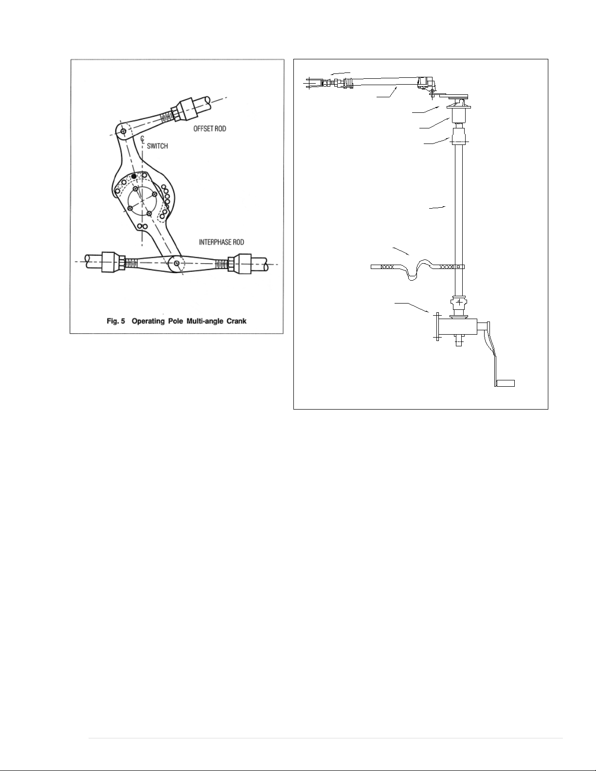
Step 11—Install Pipe Splice and Guide Plate
When the structure height exceeds 23 feet, a
pipe splice and a guide plate are furnished
and should be installed as shown in Fig. 6.
The pipe spice and both pieces of pipe are
predrilled to receive the 5/8” diameter pins.
The guide plate should not be solidly
mounted until after the vertical pipe has
been completely installed. Then bolts
holding the guide plate on the structure
should be tightened in order that the holes in
the guide plate line up with the normal
position of pipe. This assures that there is no
binding.
Step 12—Install Operating Mechanism
Either a swing handle or a worm gear
mechanism is (normally) supplied for
manual switch operation.
Swing Handle Operator
To install the swing handle operator:
With ground strap in place on vertical operating
pipe, slide handle and handle lock plate over the
end of the vertical operating pipe. Fasten the
lock plate at the proper location. Recommended
height for the lock plate is 3 ft. 6 in. above
ground.
Note: The lower end of the vertical operating
pipe should extend through the lock plate at
least 3 inches. It may extend as much as 3 feet
or more, just so it doesn’t touch the ground or
column footing.
The lock plate assembly consists of two
castings, mounted on the pipe guide plate, which
can be easily adjusted in an arc to provide the
required rotation. These act as locks for the
manual operating handle when it is dropped
from the operating position. The handle must be
raised to a horizontal position for operation.
With the switch in the fully closed position, set
the handle clamp so its set screws are 4 inches
above the lock plate and its vertical centerline is
at or near as possible to the closed position.
Temporarily fasten the handle to the pipe with
the set screws. Operate the switch and move the
adjustable lock castings until they exert pressure
against the handle in both the open and closed
positions of the switch. This provides a slight
torsional wind-up in the operating pipe. Tighten
the two piercing set screws on the handle clamp
until holes are punched into the pipe and
continue until the screws are firmly seated.
Worm Gear Mechanism
With ground strap in place on vertical operating
pipe, slide worm gear mechanism (Fig. 8) over
the vertical operating pipe and attach it to the
structure. Remove the small position indicators,
which are attached to the worm gear coupling
with Allen set screws. Tighten hex head set
screws in the coupling until the vertical
operating pipe is pierced. The three-pole switch
should now be operated manually to check for
proper adjustment. If all stops at switch
elevation have been set, including the offset
bearing, then it is safe to reinstall the position
indicators on the worm gear mechanism. These
indicators should not quite touch the raised boss
on the worm gear housing in either the open or
closed position. There is a possibility of damage
to the indicators or the coupling if this is not
observed
Motor Operator
For remote operation, a motor operator is
supplied and it should be installed per the
instructions supplied with it.
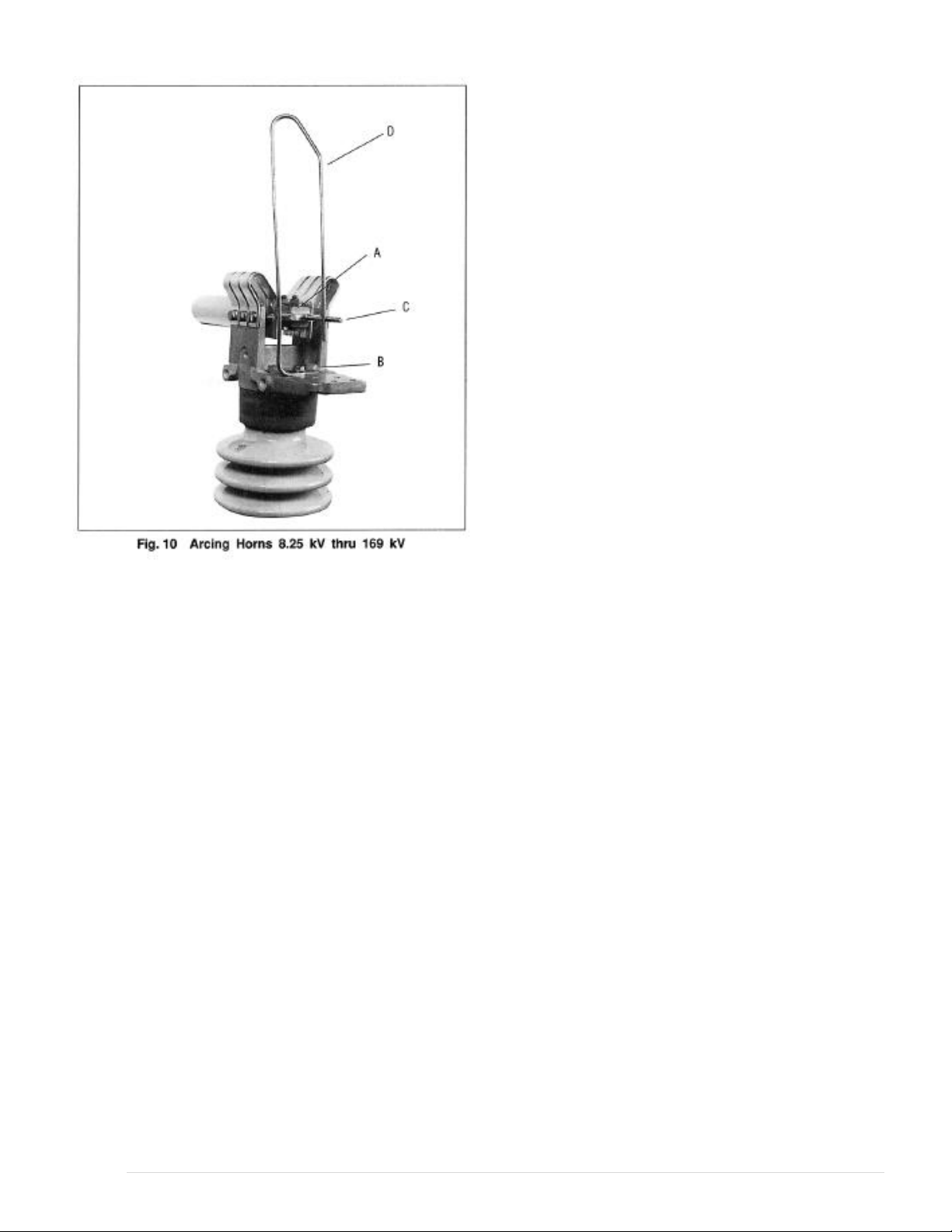
Step 13—Arcing Horn Installation (When
Supplied)
When arcing horns are used on switches, they
should be installed and adjusted after mounting
the switches on the structure. Arcing horns are
furnished only when horn gap switches are
ordered. Fig. 10 shows arcing horns used on
switches 8.25 thru 169 kV. The movable strait
horn (C) is assembled be screwing it into the
blade end. Tighten the locking nut seat securely
against the end of the blade (A). The stationary
horn is positioned properly on the jaw with the
saddle clamp, and bolted (B). This stationary
horn should be adjusted or even bent slightly to
give light contact pressure between the two
horns over the entire length if the movable horn.
Arcing horns for 242 kV switches are essentially
the same as Fig 10 with the stationary horn
contacting the movable horn at the surface
between the end of the blade and small corona
ball which is affixed at the end of the movable
horn.
Arcing horns for switches 362 thru 8000kV do
not use a movable horn. Instead the stationary

horn makes contact with the rear surface
(corona-protected surface) of the corona ball.
Note: Always check switch operation mechanism
drawing for type of arcing horns supplied.
Step 14—Installation of Corona Rings and
Balls
Corona rings and balls, when supplied, should
be installed as shown on the single-pole
drawings. Prepare areas where ring supports
contact switch parts per instructions for
aluminum connections at right.
1. 169 kV switches and below do not require
corona rings or ball.
2. 242 kV switches use corona rings at the jaw
end and a small ball on each end of the
blade.
3. 362 kV switches and above use rings at both
ends and a large ball on the end of the blade.
After these are installed, the switches should
now be ready for service.
Step 15—Final Checks
The completed 3-pole installation should be
checked for the following:
1. In the open position, the blades should stand
essentially vertical.
2. In closing, blades should make central entry
into their jaws at approximately the same
time.
3. In the closed position, all blades must be in
full contact and horizontal within tolerances.
4. In opening, the blades should rotate to
relieve the jaw contact pressure. (If the blade
remains flat, the blade beaver tail will
engage the stops formed on the jaw fingers
and further operating effort can result in
mechanical damage.) Recheck base crank
orientation per step 4.
Terminal Connections
The aluminum surface of the terminal
connection provides for easy current transfer.
Notice: In cases where a copper conductor is
used, bolt a tinned terminal clamp (if available)
to the aluminum switch terminal pad.
If a non-tinned terminal clamp is used, apply a
liberal amount of electrical joint grease at the
joint and all over the pad of the fitting.
To connect aluminum-to-aluminum
terminals:
1. Clean all contact surfaces of conductors and
fittings using a stiff wire brush to remove
heavy oxide coatings until the aluminum
finish is visible and restored.
2. Coat these now clean contact areas with a
liberal amount of corrosion inhibitor such as
NO-OX-ID”A Special” or No. 2 EJC.
3. Abrade the contact surface through the
corrosion inhibitor again using the stiff wire
brush.
Notice: Do not remove the compound.
4. Connect the terminals and torque the bolts
as per Table 1.
To connect copper-to-aluminum terminals:
1. Except for plated surfaces, clean all contact
surfaces of conductors and fittings using a
stiff wire brush to remove heavy oxide
coatings until the aluminum finish is visible
and restored.
2. Prepare any bare copper surfaces in the
usual manner.
3. Coat these now clean contact areas with a
liberal amount of corrosion inhibitor such as
NO-OX-ID “A Special” or no. 2 EJC.
4. Abrade the contact surface through the
corrosion inhibitor using a stiff wire brush.
Notice: Do not remove the electrical joint
grease.
5. Connect the terminals and torque the bolts
as per Table 1.
9 | Page

MAINTENANCE
WARNING
Before servicing the switch, be sure it is
disconnected from all electric power
sources and properly grounded.
A certain amount of care and inspection is
recommended. The frequency of inspection
depends upon atmospheric conditions and
frequency of operation. The service interval is
largely determined by the user. Recommended
maintenance is similar to that listed in the latest
industry standards.1First, it is important that the
insulators are always clean. It is also important
1ANSI C37.35 (American National Standard Guide
for the Application, Installation, Operation and
that the contacts be examined to see that they are
aligned, clean, and have a firm uniform pressure.
If the contacts are pitted, or burned to some
extent, they should be removed and replaced.
Under normal service conditions, the jaw
contacts should be examined and maintained at
least once a year, depending upon the type of
atmosphere to which they are exposed.
Periodic maintenance should consist of cleaning
the contact surfaces thoroughly by carefully
scraping off any contamination or deposit and
sanding the surface entirely clean, a coating of
lubricant should be applied. Suggested
lubricants are MOBIL 28 grease of NO-OX-ID
“A Special”. MOBIL 28 is an Exxon Mobil
Company product. NO-OX-ID is made by
SANDCHEM INC.
Maintenance of High-Voltage Air Disconnecting and
Interrupter Switches)

In general, operating linkages require virtually
no maintenance. However, in contaminated
atmospheres of where operation under sleet
conditions is common some lubrication at pivot
points may be desirable. The grease used should
be durable even when exposed to the elements,
and should retain its viscosity over a wide
temperature range.
COUNTERBALANCE
For voltage or current ratings in which blades
are counterbalanced, Fig. 11 shows proper
connections and the proper location of the drain
holes for the various switch mountings. The
counterbalances are assembled at the factory for
the mounting positions as required for each
installation. If it is necessary to change the
mounting position of the switch in the field, the
counterbalance must be changed, as described
below.
UPRIGHT TO VERTICAL
WARNING
When performing this procedure, use care
because parts are in tension.
1. Open the switch blade to approximately the
75 degree position.
2. Clamp the plunger of the counterbalance
with vise grip pliers against the face of the
housing.
3. While maintaining a good hold on the blade
with your hand, carefully open the blade a
few more degrees or enough to relieve
pressure.
4. Remove pin (A) which attaches the plunger
to the blade hinge casting. Since this pin is
larger in diameter at the center and two
shoulders hold it in place, the pin may be a
bit difficult to remove.

5. Lower the blade to approximately a 15
degree angle
6. At or near this point, the counterbalance
plunger can be connected to the proper point
for vertical mounting.
7. Raise the blade to relieve pressure.
8. Remove the vise grip pliers
9. File off any burrs on the counterbalance
shaft.
CHANGE TO INVERTED
WARNING
When performing this procedure, use care
because parts are in tension.
Additional parts are required, contact the
factory before proceeding.
1. Start with the switch blade in the CLOSED
position.
2. Clamp the counterbalance plunger with the
vise grip pliers against the face of the
housing.
3. Raise the blade slightly to relieve pressure.
4. Remove pin (A) which attaches the plunger
to the blade hinge casting. Since this pin is
larger in diameter at the center and two
shoulders hold it in place, the pin may be a
bit difficult to remove.
5. Remove pin (B) at the rear of the
counterbalance. The unit is now free to
invert, so that drain holes will be located as
shown for inverted mounting.
6. Re-connect the rear of the counterbalance
with Pin B.
7. Remove the jaw assembly from its support
insulator.
8. Lower the blade below the CLOSED
position and connect the counterbalance
9. plunger to the proper point for inverted
mounting with pin (A).
10. Raise the blade to relieve pressure.
11. Remove the vise grip pliers.
12. File off any burrs on the counterbalance
shaft created from the vise grip pliers.
13. Re-install the jaw assembly; hand tighten the
bolts.
BEARINGS
The bearing of each switch and offset bearing is
a greaseless type. Fig. 12 shows the location of
stop bolts and switch cranks on all switch
bearings. Fig. 13 shows the required location of
stop blots (5) and stop cranks (9) with a typical
location of the adjustable radius crank (8) on the
offset bearing. Fig. 14 is an elevation view of a
switch bearing.

CRANKS
The two switch poles that are not connected to
the offset bearing normally use a single crank,
similar to Fig. 15. The switch pole that is
connected to the offset bearing (drive phase)
uses either a solid double crank, or a two piece
adjustable crank, as shown in Fig. 5. The offset
bearing used a two piece adjustable radius crank
plus a separate stop crank with multiple
mounting holes for angular adjustment. Figs. 16
and 17.
INSTRUCTIONS FOR SPECIAL SWITCHES
For switches specifically designed to operate
under abnormal ice conditions, it is important
that they be adjusted to assure the switch blade
(on a closing operation) exerts force on the jaw
stop.
FORCE VALUES
Switch Voltage Force on Stop
8.25 thru 169 kV 80 lbs.
242 thru 840kV 40 lbs.
The blade force adjustment should be made after
the switch instillation is complete, as described
previously in this instruction manual, except for
the corona rings.
The blade force adjustment is made as follows:
Start with the three-pole switch in a position so
that the blade end contacts are at least 1 foot
from the stationary contact fingers. Using the
manual operator, and observing one switch pole,
lower the blade into the finger contact assembly
and continue to close the switch to the point
where it rests on the stop and there is
approximately 1/8” clearance between the blade
end contact and the stationary contact fingers on
each side, see Fig. 19. This is the point at which
the blade force is to be measured. It is important
that the 1/8” clearance is obtained as the switch
is being operated toward the closed position as
described and never as the switch is being
opened. This would cause an improper
adjustment.
Using a force gauge, measure the force exerted
by the blade on the jaw stop by either pushing
the blade up from below and noting the lbs. at
which the blade is lifted off the jaw stop, or by
putting a wire loop around the blade and lifting
it with the gauge and noting the lbs. required.
The place on the blade at which the force is
measured should be just outside the finger
contact assembly, see Fig. 18. If the force
required is not proper, an adjustment must be
made at the hinge end of the switch. To make
the necessary adjustment, move the switch blade
to a convenient point near the full open position
and remove crank pin (B), Fig. 18, then move
and twist blade or forked link (D) to disengage
clevis (C) from crank.
If the force measured was too high, turn the
clevis (C), 1/2 turn into the forked link (D). But
if the force measured was too low, turn the
clevis (C) 1/2 turn out of the forked link and re-
connect the clevis. Check the threads on the
clevis, some switches have right hand threads
and others have left hand threads. Close the
switch to the point previously described and
again measure properly, another adjustment
must be made. Repeat the procedure previously
described. After one switch pole is satisfactorily
adjusted, the other two poles should then be
adjusted in the same manner.
Table 1
Lubrication Guide for Outdoor Switch Components
Part Name Type Lubricants
Recommended
Amount
Applied
Qty. Req’d. for
(6) Three-pole
Switches
Jaw Fingers
NO-OX-ID Grade “A”
Special or Mobil 28
Grease
Medium
Coat
Blade Ends
NO-OX-ID Grade “A”
Special or Mobil 28
Grease
Medium
Coat (1) Quart
Pins On current
carrying parts
Mobil 28 Grease or DC-4 *
Pins On control
parts
Mobil 28 Grease or DC-4 Light Coat (1) Quart
Bearing Areas
On control parts
Mobil 28 Grease or DC-4
Medium
Coat
Terminal
Connections
NO-OX-ID Grade “A”
Special or NO 2 EJC
Heavy
Coat
(1) Quart
13 | Page

RENEWAL PARTS
Refer to the switch nameplate when ordering renewal parts. The nameplate is attached to the
base assembly of each switch pole. The same data is shown on the record engineering drawings.
The master file at the factory is linked to the serial number on the nameplate.
Renewal Parts Ordering Information
Serial Number
Switch Type
Part Name
Quantity Required
Max. kV
B.I.L. kV
Cont. Amps
Mom. Amps
Refer your requests for renewal parts to the Factory.
14 | Page
Table of contents
Popular Industrial Electrical manuals by other brands

Murata
Murata GRM3195C1H223JA01 Series Reference sheet

Murata
Murata GRM1557U1A472JA01 Series Reference sheet

HALE
HALE SmartFOAM 1.7AHP Description, Installation and Operation Manual

Murata
Murata GRM3195C1H152JA01 Series Reference sheet

Murata
Murata GRM155R61C105KE01 Series Reference sheet

Murata
Murata GRM1885C1H8R2DA01 Series Reference sheet

Murata
Murata GRM0225C1E9R5WA03 Series Reference sheet

Murata
Murata GRM0335C1E1R5BA01 Series Reference sheet

Siemens
Siemens TA6PG750 installation instructions

Eaton
Eaton Series NRX Installation and Removal Instructions

sprecher + schuh
sprecher + schuh CA8 Series quick guide

Copeland
Copeland OME-16T-TEM Quick installation guide