.
Feel free to visit us at: www.b2audio.com & at facebook; www.facebook.com/b2audio
9
The protection circuits of the amplifier prevents severe damages from faulty conditions & improper use.
The protection indicatior will switch on due to short circuit connection & speaker overload, thus the amplifier will be turned off.
Prior to inspecting the occurred problem, turn all levels down & all power off, then carefully check the installation for
wiring mistakes, shorts or faulty ground (GND). If the amplifier shuts down due to excessive heat, the protection indicator will
light up; please allow time for the unit to be cooled off. Before removing your amplifier, refer to the list below and follow the
suggested procedures step by step. If not at ease, contact an authorized installer which can assist you.
PROTECTION LED IS LIT ONCE THE AMPLIFIER IS TURNED ON
FUSE BLOWING
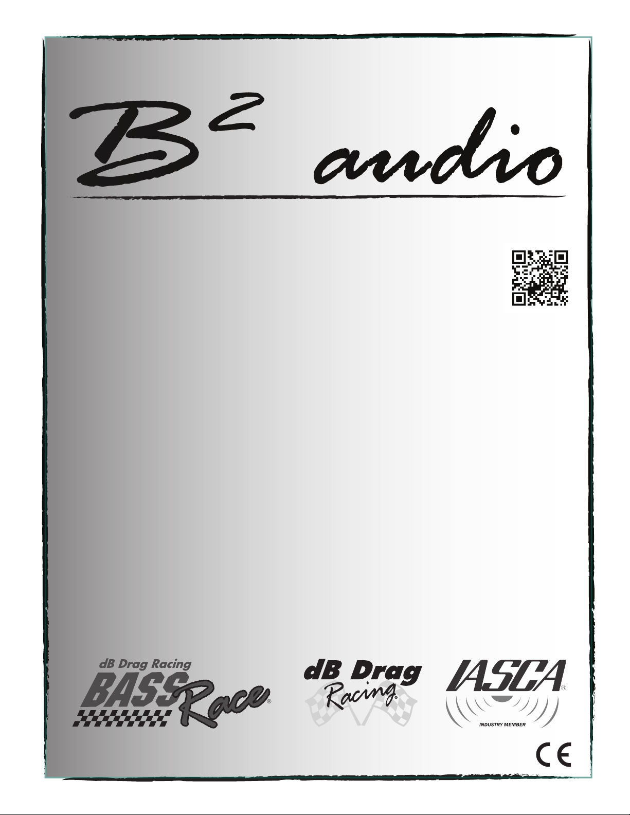
Measure the speaker impedance & that it is in accordance with the configuration.
Check speaker shorts.
Ensure airflow around the amplifier is sufficient & that the amplifier is not installed in
areas of excessive vibration.
AUDIO OUTPUT INSUFFICIENT - DISTORTED SOUND
Ensure that the gain settings on the amplifier is matched with the output level of the head unit.
Adjust the head unit volume.
Check speaker shorts.
Adjust the crossover frequencies in accordance with the setup.
HIGH HISS-ENGINE NOISE IN SPEAKERS
Measure the speaker impedance & that it is in accordance with the configuration.
Inspect the power cable for shorts along with vehicle chassis.
AMPLIFIER DOESN’T TURN ON
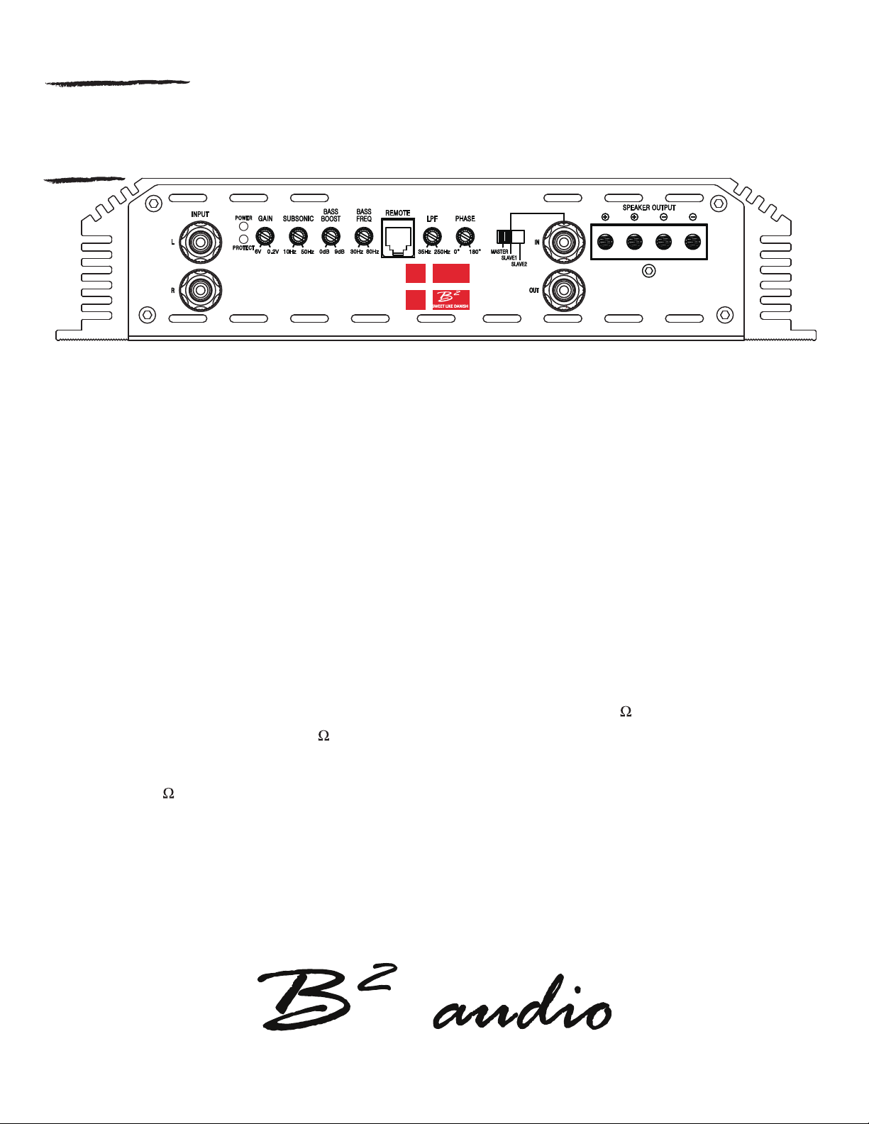
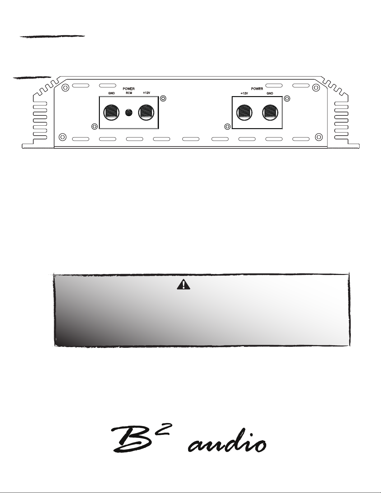
Measure voltage on the +12V terminal.
Ensure that the remote terminal has min. 13.8V DC remote connection.
Recheck the ground (GND) connection. Inspect the in-line fuses.
Check the protection LED is not on.
Check shorts on speaker wires & the connected load / impedance. Check power cables & GND.
Disconnect the speaker cables and reset the amplifier.
High / Low voltage, operation voltages is 9v ~ 15v. Voltages beyond this will cause the amplifier to go into protect.
OVERHEATING
If no output at all, check the RCA connections & the cable itself.
Ensure that all signal transferring wires (RCA, speaker cables etc) are kept seperately / away from
the power and the ground wires.
Bypass all electrical components between the Head unit and the amplifier.
Connect the Head unit directly to the amplifier’s input. If the noise is eliminated, the unit bypassed
is the one causing the noise.
Remove the existing ground wires for all electrical components installed. Ensure that the point of
ground is 100% metal which has been grinded free of rust, paint etc.
Replace the ground cable from the OEM battery / alternator and ensure it is grounded accordingly.
Test the battery and alternator load (can be carried out by a professional).
Ensure that the vehichle’s electrical system is in a good condition, this includes distributor, alternator,
spark plugs / wires, voltage regulators etc.
TURN ON THUMP
Disconnect the signal input to the amplifier, then turn it on and off.
a) If the noise is cancelled, then connect a delay turn on module on the REM wire running from
the source unit to the amplifier.
b) Use another 12V source for REM lead to the amplifier. If the noise is cancelled, use a relay
to isolate the amplifier from the turn on thump.
4. Troubleshooting