B2 Audio rage 1500 User manual

rage 1500 / 3200 / 1200.4
product id: rage1500fr22
rage3200fr22
rage1200.4fr22

power / speaker
connections
rage
Don’t blow a fuse, keep calm. The next era comes with our redened levels. The Rage series is “The increased Desire for B2 audio”. The Rage should cover
any need for near any type of user. Mono, 4ch or even mini size amplication, no problem, Rage covers it all. Enough power and authority rened with
the keystones of B2 audio will provide you with numerous hours of joy and sweetness.
The added bonus is that these amplifers not only are ecient, but they are compact as well.
To obtain the full potential of any amplier & to minimize failure, it is adviced to upgrade your stock electrical system. Don’t take any shortcuts, a better
electrical equals enhanced performance and stability.
installation 8
*preparations
* power connectors
* remote & rca input
troubleshooting 9
warranty info 10
4-5
6-7
3
introduction
table of content


4
Panel layout
Rage 1500 / rage 3200
gnd (Ground connection) Rem (+12v switched)
Connects to the vehicle’s chassis. Keep as short as possible Switched 12v connection from source unit. It is adviseable
(<20”/ 50 cm) Using wire with a maximum gauge specied to use a common relay to ensure a stable voltage connection
to the terminal ensures optimal operation. without dips.
+12v (power connection) led indicators
Connects to the positive terminal of the battery. For Power lit, amplier is operational and on.
optimal performance, use wire specied to the power Clip ashing shows the signal is not clean at peaks. Clip lit,
terminal. Fuses shall be placed within 8” / 20 cm of the signal is heavily distorted. The loudspeaker & the amplier
battery. can be damaged over time. Protect lit, the amp has shut o.
Could be caused by install, thermal shutdown, short circuit,
low voltage & circuit damage to the pcb.
Gain (6v~0.2v) HPf (12 db/oct)
Adjusts signal input voltage from the input source to match Variable high pass crossover from 10 Hz to 2 KHz.
the ampliers input stage. 6V ~ 0.2V is the voltage range. It is highly recommended to set it according to the tuning
Sudden voltage spikes or voltages beyond the above may of your loudspeakers enclosure / t/s parameters to
cause errors or damages to the input section. Eventually avoid unnecessary strain to your sound system.
the amplier can go into protect. It is advisable to use a
low (< 1V) input if the amplier is driven into a low ohm lPf (12 db/oct)
load. Variable low pass crossover from 50 Hz to 20 KHz, if used with
HPF, it will create a bandpass cong.
input remote port
RCA input signal from the source unit. Use a signal of min Connection of external level controller with voltmeter &
0.3V ~ 6V max to ensure proper operation. clipsensor. Caution, it is not a volume knob & shall be
adjusted in accordance with the ampliers gain.
speaker output
2 pin layout speaker terminal. Do not attempt to bridge
externally. The minimum load is 1 Ω.
Any connection below 1 Ω is not warranted. The amp can’t be
strapped or bridged in any way either.
This circuit design will have a high output voltage on BOTH
speaker terminals, even after the amplier has been shut of
for a while. For any connections or changes in conguration,
do measure if voltage is still present prior to doing so. This
will avoid potential shorted circuits.
GND
REM
+12V
POWER
P ROT ECT
CLIP
R EMOT E
+-
S P EAKE R
MIN MAX
GAIN
2KHz 20KHz
HPF LP F
10 50
INPUT
R
L
R A G E 3 2 0 0
1 OHM MINIMUM

5
Panel layout
Rage 1200.4
gnd (Ground connection) Rem (+12v switched)
Connects to the vehicle’s chassis. Keep as short as possible Switched 12v connection from source unit. It is adviseable
(<20”/ 50 cm) Using wire with a maximum gauge specied to use a common relay to ensure a stable voltage connection
to the terminal ensures optimal operation. without dips.
+12v (power connection) led indicators
Connects to the positive terminal of the battery. For Power lit, amplier is operational and on. Clip ashing shows
optimal performance, use wire specied to the power the signal is not clean at peaks. Clip lit, the signal is heavily
terminal. Fuses shall be placed within 8” / 20 cm of the distorted. The loudspeaker & the amplier can face damage.
battery. Protect lit, the amp has shut o. Could be caused by install,
thermal, short circuit, circuit damage & low voltage.
speaker output
4 ch speaker connection, use maximum sized wire. BP/Full/HP
Connect according to the labelling. Do only bridge as Crossover type selection, bandpass / fullrange or highpass
indicated with a 4 ohm load or run 2 ch stereo.
Gain (6v~0.2v) HPf (12 db/oct)
Adjusts signal input voltage from the input source to match Variable high pass crossover from 20 Hz to 4 KHz.
the ampliers input stage. 6V ~ 0.2V is the voltage range. It is highly recommended to set it according to the tuning
Sudden voltage spikes or voltages beyond the above may of your loudspeakers enclosure / t/s parameters to
cause errors or damages to the input section. Eventually avoid unnecessary strain to your sound system. The x 10
the amplier can go into protect. It is advisable to use a switch mulitplies the crossover range by a factor of 10.
low (< 1V) input if the amplier is driven into a low ohm
load. lPf (12 db/oct)
Variable low pass crossover from 50 Hz to 5 KHz, if used with
input HPF, it will create a bandpass cong.
RCA input signal from the source unit. Use a signal of min
0.3V ~ 6V max to ensure proper operation.
FR
R A G E 1 2 0 0 x 4
4OHM MINIMUM

Power / speaker connection
Rage 1500/3200
speaker output
2 pin layout speaker terminal. Do not attempt to bridge
externally. The minimum load is 1 Ω.
Any connection below 1 Ω is not warranted. The amp can’t be
strapped or bridged in any way either.
This circuit design will have a high output voltage on BOTH
speaker terminals, even after the amplier has been shut of
for a while. For any connections or changes in conguration,
do measure if voltage is still present prior to doing so. This
will avoid potential shorted circuits.
GND
REM
+12V
POWER
P ROT ECT
CLIP
RE MOT E
+-
S P EAK ER
MIN MAX
GAIN
2KHz 20KHz
HPF LP F
10 50
INPUT
R
L
R A G E 3 2 0 0
1 OHM MINIMUM
100 A (External fuse) for
RAGE 1500.
250 A (External fuse) for
RAGE 3200
6

Power / speaker connection
Rage 1200.4
speaker output
8 pin layout speaker terminal. Do not attempt to bridge
externally. The minimum load is 2 Ω stereo or 4 Ω bridged!
Any connection below 2 Ω is not warranted. The amp can’t be
strapped or bridged with another amp in any way either.
For any connections or changes in conguration,
do measure if voltage is still present on terminals prior to doing so. This
will avoid potential shorted circuits.
7
FR
R A G E 1 2 0 0 x 4
x4CH
4OHM MINIMUM
100 A (External fuse)

Installation
Installation considerations
If you choose to install the amplier by yourself, please read the entire owner’s manual carefully.
Before you start your installation, please take all steps into consideration.
If in doubt, please go to www.b2audio.com for authorized distributors / dealers that will be able to
congure your set up & ensure the warranty of your amplier.
Disconnect the negative (-) battery cable before mounting or making any connection.
Check the battery & alternator ground (-) connection. Make sure they are properly connected/dimensioned
& free of corrosion. Before selecting a mounting location for the amplier, please take cooling & safety
into consideration. Avoid areas with excessive vibration & up side down installation!
In order to avoid excessive heat from the amplier, it is recommended to nd a mounting location
that allows for vertical positioning of the heatsink ns. For safety purposes, install the amplier in a dry and
well ventilated location and make sure no cables or other harness of the car is interfaced with the mounting
location or will present a hazard to the car’s cable, control cables, fuel lines/tanks, hydraulic lines or other
components of the vechicle. Route the RCA cables away from high current wires, if possible run RCA, Power and Speaker
cables individually and with a good distance from each other.
12V (Power connection)
Before mounting the amplier, disconnect the negative (-) wire from the battery to protect any accidental
damage to the amplier or the audio system. The ampliers are equipped with 0 AWG power & ground terminals.
It is crucial that all terminals are used with the adequate cable to ensure correct operation.
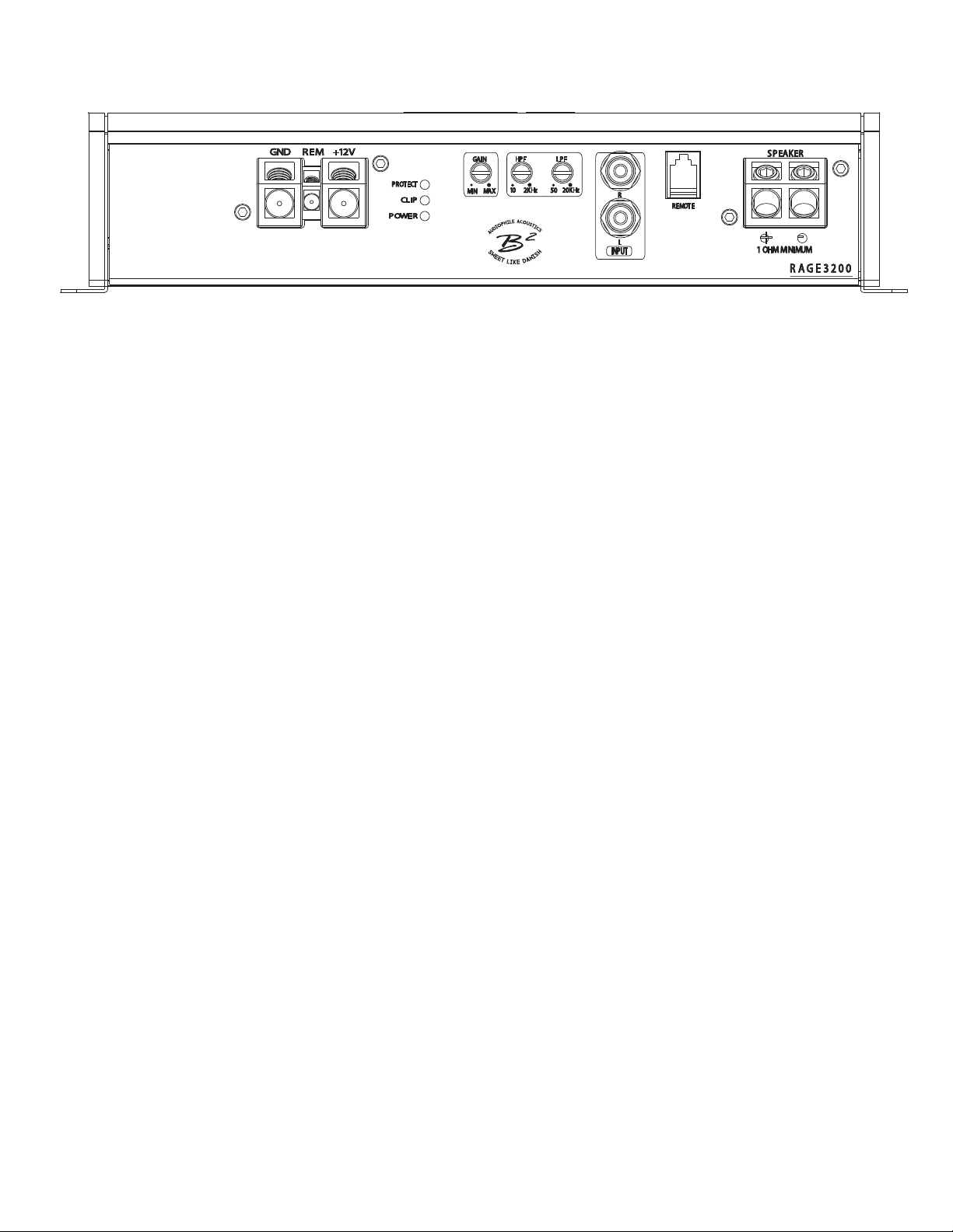
Connect the power cables to the power terminal labeled as +12V.
The amplier is not equipped with fuses, so external fuses are required at both the battery and the amplifer.
Connect one end of the fuse holder to the power cable and the other end of the fuse holder to the positive
battery terminal within 8’’ /20 cm of the same cable. The same shall be done at the other end of the cable that
connects to the amplier. The fuses will protect the system and the vehicle against the possibility of
a short circuit in the power cable. Make sure that the fuses and the fuse holder is according to the system requirements.
GND (Ground connection)
Locate a secure grounding connection as close as possible to the amplier.
Make sure the location is clean and provides a direct electrical connection to the chassis of the vehicle.
Connect one end of an equal sized cable as the positive cable to the location of ground.
It is important that the ground cable is as short as possible, but no longer than 20’’ / 50 cm at maximum.
Run one end of the cable to the grounding point. Run the other end of the cable to the mounting location.
Connect the ground cable to the terminals labeled as GND.
REM ( REMOTE CONNECTION )
Run a remote turn on cable from the switched +12 V source.
This may be a toggle switch, a relay, the source unit's remote ouput cable or power antenna trigger cable.
Connect the remote turn on cable to the power terminal labeled as REM. The REM out terminal is mainly intended for
connection of another amplier ran in a chain, but it can also be used for other units.
INPUT (RCA CABLE)
Run the RCA cables away from the high current cables / speaker cables and connect to the amplier.
Use high qualtity cables with a secure grounding point to avoid amplier malfunction and / or alternator whine.
8
Power connectors
Preparation

9
10 V ~ 17 V.
troubleshooting
amplifier doesn’t turn on
protection led is lit once the amplifier is turned on
fuse blowing
overheating
audio output insufficient - distorted sound
turn on thump
high hiss - alternator whine

This manual suits for next models
5
Table of contents
Other B2 Audio Speakers manuals