Bake Max TCO6G User manual

Combi Oven Touch
TCO6G
MODELS
TCO6E
TCO7G
TCO7E

FOR YOUR SAFETY
Do not store or use gasoline or other flammable vapors or
liquids in the vicinity of this or any other appliance.
WARNING
Improper installation, adjustment, alteration, service, operation or maintenance can cause property
damage, injury or death. Read the installation, operating and maintenance instructions thoroughly
before installing, operating or servicing this equipment.
NOTICE
Instructions must be posted in a prominent location that will provide the user of this equipment with
procedures, in the event he/she smells and/or detects gas. This information must be obtained by
consulting the local gas utility.
WARNING
Electrical Grounding Instructions
This appliance is equipped with a three-prong (grounding) plug for your protection
against shock hazard and should be plugged directly into a properly
grounded three-prong receptacle. Do not cut or remove tie grounding prong from this plug.

WELCOME TO THE TOUCH WORLD
Congratulations on your new purchase! From now on you have in your kitchen a legitimate
Combination Oven with BAKEMAX touch screen technology, one of the icons of the
world-class food service industry. We brought together the best components with the highest
technology combined to the construction made by hand individually by our team. We make no effort
to present this equipment.
So that your device performs best, please read this manual carefully and follow the instructions
correctly. If you have any doubts and/or suggestions, call Venâncio, qualified professionals will be
at your disposal
RECEIPT
We recommend the care and inspection to detect any damage during transportation, such as:
- Breaking or kneading of parts;
- Lack of parts;
- Penetration of water or other liquids.
In the event of any damage during transportation, it must be noted to the carrier's notice, notifying
the plant immediately.
Keep these instructions because it will be very helpful to answer questions and
ensure the proper operation and maintenance of the equipment.

IMPORTANT: READ THIS BEFORE INSTALLING THE EQUIPMENT!
BAKEMAX
cannot be held liable for any material or personal injury resulting
from failure to comply with any instructions presented in this manual.
The power and other data required for installation are available in the tables in the
"Technical Characteristics" section of this manual.
The equipment should only be installed in accordance with the standards set forth
in this manual.
Before installation, make sure that the voltage, frequency, and power are in
accordance with the points installed.
This equipment is a convertible voltage, DO NOT ATTEMPT TO CHANGE THE
VOLTAGE as it may be severely damaged and is not covered under warranty. If
necessary, contact the plant for advice to our nearest service station.
The equipment must be grounded electrically.
Do not install before solving any doubts regarding the correct construction of the
installation points detailed in this manual.
IDENTIFICATION OF EQUIPMENT
The equipment is identified by a nameplate on which the serial number is registered. This so
that records of possible modifications made to the components can be keps, this is located on the
left side of the equipment.

GENERAL TECHNICAL DATA OF THE EQUIPMENT
POWER GRID
VOLTAGE OF THE EQUIPMENT: check if the voltage of the equipment is the same as the
connection point.
The socket-outlet where the equipment is to be connected must be single-phase or three-phase,
rated for the rated current of the protection circuit (thermoelectric circuit breaker), allowing full
insertion of the plug pins, without any gaps, so that live parts are not accessible to touch.
Model TCO6G/TCO7G TCO6E/ TCO7E TCO10G / TCO12G TCO10E / TCO12E
No. of Meals Approx. 350 Approx. 350 Approx. 500/600 Approx. 500/600
Gas 0,8 -
1,2 -
Three-phase voltage (V) - 220/380/440 - 220/380/440
Single Phase Voltage (V) 110/220 - 110/220 -
Installed power (Kw) 0,3 10,5 0,3 18
Gas power / heating 9000kal - 17200kal -
Power consumption (kw / h) 0,1 5,3 0,1 6.5
Gas consumption (kg / h) 0,8 -
1,2 -
Water inlet (BSP) 3/4" 3/4" 3/4" 3/4"
Drain Ø 1.1/2” Ø 1.1/2” Ø1.1/2” Ø 1.1/2”
Height (mm) 900 900 1200 1200
Width (mm) 1025 1025 1025 1025
Depth (mm) 830 830 830 830
Net weight (kg) 140 126 180 160
Capacity (Gns prof.65mm) 6/7 GNs 1x1 6/7 GNs 1x1 10/12 GNs 1x1 10/12 GNs 1x1

TABLE OF BREAKERS ACCORDING TO TYPE OF EQUIPMENT
Grounding or ground wire: The ground wire of your equipment must be connected to an
efficient ground cable, avoiding personal hazards. The connection of the ground wire is
necessary at any voltage, and should not be connected to the neutral wire of the taps,
hydraulic piping, electric, gas network, etc. For a correct grounding, observe the instructions
in accordance with local codes.
THE CONNECTION OF THE GROUND WIRE IS INDISPENSABLE
Electrical extensions, T-pins, adaptors or the liker: do not use in any case, to connect
other devices in the same socket-outlet. Doing so may cause overloading of the electrical
installation and/or poor contact. Overloads can cause harmful heating to the insulation,
connections, terminals or near the conductors, causing damages and even the burning of the
installations and the product.
Voltage fluctuations: if the voltage of your establishment displays fluctuations that are not
in accordance with the permitted fluctuations, ask the utility company for regularization, or in
cases of impossibility, install an automatic stabilizer according to the maximum rated power.
Circuit breaker: in the circuit in which the equipment will be connected, there must be a
thermoelectric protection circuit breaker (see following table).

technical pressure specifications which must be at least 0,8 kg/f maximum of 2 kg/f.
The hose connection that accompanies the Combi Oven TOUCH is a ¾" BSP threaded fitting.
Observe in the equipment installation if it has the water pressure specified in the technical
data sheet of the product. If this does not occur, add a pressure reducer, as shown below.
NOTE: The pressure reducer is supplied with the equipment.
OVEN INSTALLATION
Location:
1 - Provide on the installation site:
* Box with circuit breaker and fuse; (see table of circuit-breakers according to the type of equipment);
* Electric power socket-outlet (see power grid);
* Socket-outlet (see power grid);
* Point for drainage of water (drain or sewage); (Refer to GENERAL EQUIPMENT DATA)
Note. DRAIN OR FLOW POINT IS OF EXTREME IMPORTANCE. PIPING FOR HOT
OR METALLIC PIPING SHOULD BE PROVIDED WITH 1" ½" INPUT. We orientate
the use of metallic tubes or weldable CPVC of the best brands of the market.
* Water supply point with valve.
HYDRAULIC NETWORK
Water inlet: it is required a fixed water inlet point, preferably exclusive, which meets the
THE EQUIPMENT MUST BE INSTALLED WITH ADEQUATE BACKFLOW PROTECTION
TO COMPLY WITH APPLICABLE FEDERAL, STATE, AND LOCAL CODES.

UNPACKING
1. Remove all packaging and transit protection including all protective plastic coating from the exterior stainless steel panels.
2. Check the oven and supplied parts for damage. Report any damage immediately to the carrier and distributor.
3. Check that the following parts have been supplied with your oven:-
4. Report any deciencies to the distributor who supplied your oven.
5. Check that the available electrical supply is correct to that shown on the Technical Data Plate located on the front right hand
side panel.
LOCATION
1. Position the oven in its approximate working position.
2. The unit should be positioned so that the control panel and oven shelves are easily reachable for loading and unloading.
CLEARANCES
To ensure correct ventilation for the motor and controls, the following minimum installation clearances are to be adhered to:
Top 8”. 20/ 0 mm
Rear 300mm / 12”.
Left-hand side 450mm / 18”.
Right-hand side 900mm / 36”.
· Installation shall comply with local electrical, health and safety requirements.
· It is most important that this oven is installed correctly and that oven operation is correct before use.
· If you have any questions regarding the proper installation and / or operation of this oven, please contact your local
distributor.
Qualied installation personnel are individuals, a rm or a company which either in person or through a representative are engaged
in and responsible for the installation of electrical wiring from the electric meter, main control box or service outlet to the electric
appliance.
Qualied installation personnel, licensed and bonded, must be experienced in such work, familiar with all precautions required and
have complied with all requirements of state or local authorities having jurisdiction.
U.S. and Canadian Installations - All ovens, when installed, must be electrically grounded in accordance with local codes, or in the
absence of codes, with the National Electrical Code ANSI/NFPA 70 - Latest Edition and/or Canadian National Electrical Code C22.2
as applicable.
The ventilation of these ovens should be in accordance with local codes. In absence of local codes, refer
to the national ventilation code titled, Standard for the Installation of Equipment for the Removal of
Smoke and Grease Laden Vapors from Commercial Cooking Equipment, NFPA-96-Latest Edition.
The appliance is to be installed with a check valve in accordance with applicable federal, province and local codes.
FCT6/7G FCT6/7E
IMPORTANT
INSTALLATION REQUIREMENTS

THIS APPLIANCE IS INTENDED FOR OTHER THAN HOUSE HOLD USE
All BAKEMAX commerical gas appliances are manufactured by skilled craftsman using the finest quality materials.
PROPER installation by qualified personnel is essential for safe, efficient, and trouble-free operation of the unit. Any alteration and/or
tampering, without proper knowledge, tools, and test equipment, is DANGEROUS and will void all warranties. The installation must
conform with local codes, or in the absence of locel codes, with the National Fuel Gas Code, ANSIZ223.1- latest edition.
PRESSURE TESTING: FAILURE TO INSTALL PRESSURE REGULATOR WILL VOID WARRANTY.
(Most units have a convertible regulator.) The appliance and its indivdual shut-off valve must be disconnected from the gas supply
piping system during any pressure testing of that system at test pressure in excess of 1/2 psig (3.45 kPa). The appliance must be isolated
from the gas supply piping system by closing its individual manual shut-off valve during any pressure testing of the gas supply piping
system at test pressures equal to or less than 1/2 psig (3.45 kPa).
NOTICE
The proper installation of this gas appliance is the total responsibility of the end user. It is the responsibility of the purchaser to
determine that the installer is qualified in installation procedures. Conversion, connecting gas lines, calibrating thermostats, burners,
lighters, setting gas pressure with manometer, and etc., is all part of normal installation and will not be paid for under warranty. If a
warranty technician is called out and finds the unit improperly installed, the end user may be subject to billing.
FOR MAINTENANCE, SERVICE, REPAIRS, OR INSTALLATION - Contact your dealer or the factory, for your local Factory Authorized
Service Agency.
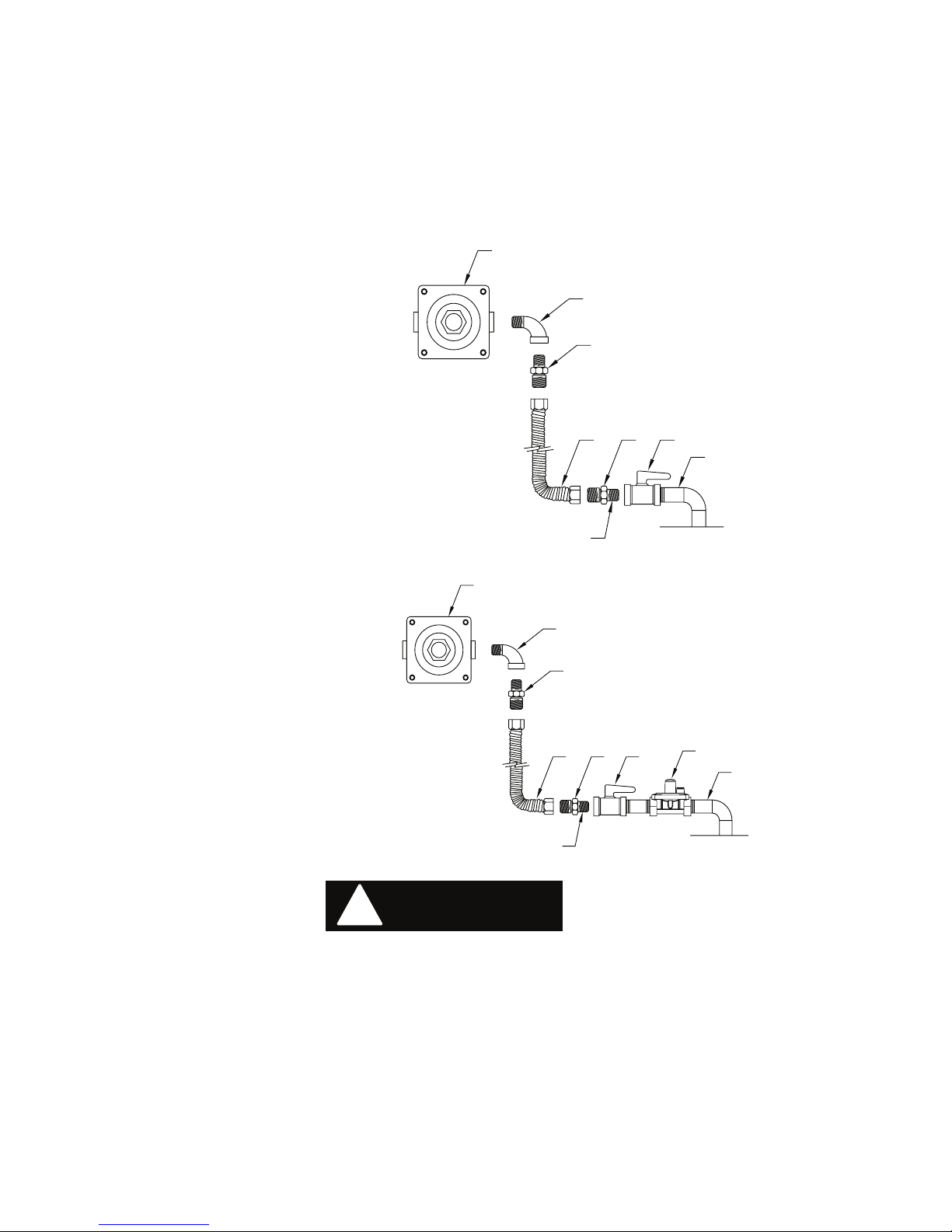
The gas pressure regulator provided with the equipment must be installed when the appliance is connected to the gas supply.
The area around the appliance must be kept free and clear of combustibles such as solvents, cleaning liquids, brooms, rags, etc.
Proper clearances must be provided at the front of the appliances for servicing and proper operation.
Provisions shall be incorporated in the design of the kitchen, to ensure an adequate supply of fresh air and adequate clearance for
air operanings into the combustion chamber, for proper combustion and ventilation.
For proper operation of the appliance, do not obstruct the ow of combustion and ventilation air.
The installation must conform with local codes, or in the absence of local codes, with the national fuel gas code, ANSI Z223.1 - 1988
(or latest addenda).
The gas supply line must be at least 3/4" NPT.
INSTALLATION - GAS STANDARDS AND CODES
1. The appliance and its individual shut off valve must be disconnected from the gas supply piping system during any pressure testing
of that system at test pressure in excess of 1/2 psi (3.45 kPa).
2. The appliance must be isolated from the gas supply piping system by closing the individual manual shut-off valve during any
pressure testing of the gas supply piping system at test pressures equal to or less than 1/2 PSI.
IMPORTANT - The installation of this appliance must conform to local codes or, in the absence of local codes, with the National Fuel
Gas Code ANSI Z223.1, Natural Gas Installation Code, CAN/CGA-B149-1, or the Propane Installation Code, CAN/CGA-B149-2 as
applicable, incluiding:
GAS INSTALLATION INSTRUCTIONS

GAS CONNECTION - The gas inlet line size of this appliance is 3/4" NPT. For proper operation, the gas supply service line must be
the same size or greater than the inlet line size of the appliance. The gas line size must not be reduced at any point along the
supply line.
MANUAL SHUT - OFF VALVE - A gas pressure regulator and a contractor-supplied shut-off valve must be plumbed in the gas service
line ahead of the appliance – in a physical location where it can be reached quickly in the event of an emergency .
A. Gas pressure regulator
A
D C E
F
G
C
B
GAS
B. 90º Street elbow
C. Adapter (must be 3/4" male pipe thread)
D. Flexible connector
E. Manual gas shut-off valve
F. 3/4" gas supply
G. Use pipe-joint compound
NATURAL
Visually double check any installer-supplied intake pipes and/or blow them out using compressed air to clear any dirt or debris,
threading chips, or other foreign matter – before installing a service line. Those particles will clog gas orices when gas pressure is
applied. Compounds used on threaded joints of this appliance piping must be resistant to the action of NG and LP gas and provide
a gas tight seal to prevent leaks.
When installing the pressure regulator - remember it can only handle 1/2 PSI. In e very LPG installation, you have high source pressures,
ranging from 20 PSI to 100 PSI. If the high pressure gas line from the LPG tank is directly connected to the unit without the proper
step-down regulator, it will rupture the diaphragm in the valve, rendering it useless.
!
WARNING
The gas pressure regulator must be installed in the gas line – failure to install a pressure regulator will void the equipment warranty.
The regulators supplied with ranges have 3/4" NPT connections; the regulator is adjusted at the factory for 4" W.C. (water column)
manifold gas pressure (natural gas) or 10" W.C. manifold gas pressure for propane gas operation.
B
C
G
F
ECD
A
A. Gas pressure regulator
B. 90º Street elbow
C. Adapter (must be 3/4" male pipe thread)
D. Flexible connector
E. Manual gas shut-off valve
F. 3/4" gas supply
G. Use pipe-joint compound
H. Step down regulator
H
LP GAS

Before connecting the regulator, check the incoming line pressure – as these regulators can only withstand a maximum inlet pressure
of 14" W.C. (1/2 PSI); exceeding this pressure will damage them. If the gas supply line pressure is greater than this amount, a step-down
regulator will be required.
A gas ow direction arrow is cast into the body of the regulator to minimize installation error – it should point downstream to the
appliance. T he blue air vent cap on the top of the regulator is part of the regulator and should not be removed.
!
WARNING
Any adjustment to the regulator must be made only by qualified and licensed s e r v i c e personnel with the proper calibrated test
equipment. Gas connections should be performed by a qualified licensed contractor.
In the event of a power failure, no attempt should be made to operate the unit during power failure.
Before lighting, check all joints in the gas supply line for leaks. Do not use an open ame to check for leaks!
1. Turn pilot valves to OFF position by turning adjustment screws clockwise.
2. Turn ON the manual gas valve at the inlet side of the gas supply line.
3. Check for gas leaks at the exible coupling or gas connector tting using a solution of one part soap and three parts water.
4. Sparingly spray or brush the soapy solution at the gas ttings; active bubbling indicates location of gas leak.
6. Turn pilot adjustment screw counter-clockwise, then light standing pilot and adjust ame 1/4" high.
7. Turn ON gas valve/thermostat to light main burners.
8. For complete shut down, shut off gas valves and turn pilot adjustment
screw clockwise to shut off gas to the pilots.
5 . If a gas leak is detected turn off the manual gas valve at the inlet side of the gas line. Call your certied and licensed
service technician.
OPERATING INSTRUCTIONS
PILOT ADJUSTMENT SCREW
MORE GAS LESS GAS
+ -
Use soap and water solution.

PROPANE GAS CONVERSION INSTRUCTIONS
A griddle is equipped with xed orice hoods and shipped from the factory for use on natural gas.
To convert to propane gas, install the propane burner orice hoods supplied as follows:
1 - Remove the griddle plate by lifting with two people and set a side.
2 - Slide the burners back off of the valve orice hoods a couple of inches and let it rest.
3 - Remove the natural gas orice hoods with a 1/2” wrench.
4 - Apply a very little bit of pipe dope on the threads of the valve.
DO NOT APPLY PIPE DOPE INTO ORIFICE HOOD.
5 - Attach the supplied propane burner orice hoods with a 1/2” wrench.
6 - Convert the pressure regulator from Natural to Propane gas by inverting the snap-in device beneath the
cap on the regulator. This will require a fair amount of pressure. Do not remove the spring. When replacing
the cap make sure the snap-in insert goes down on top of the middle of the spring.
7 - Test for proper pressure; 10” W.C. (water column) using a manometer.
8 - Slide burners back onto the orice hoods.
9 - Apply the Propane “Notice” stickert to the front of the unit for futer reference.
1 2
34
180º
PROPANE GAS
NATURAL GAS

Installation - Electric Utility Connections-Standards and Codes
Qualied installation personnel are individuals, a rm or a company which either in person or through a representative are engaged
in and responsible for the installation of electrical wiring from the electric meter, main control box or service outlet to the electric
appliance.
Qualied installation personnel, licensed and bonded, must be experienced in such work, familiar with all precautions required and
have complied with all requirements of state or local authorities having jurisdiction.
The installation instructions contained here are for the use of qualied installation and service personnel only. Installation or service
by other than certied / licensed personnel will void the warranty and will result in damage to the oven and/or injury to the operator.
!
To avoid burning, do not use any liquid or containers loaded with products to be cooked which
become fluid by heating at higher levels than those which can be easily observed. OBS .: Stick the
adhesive accompanying this manual to a minimum height of 5,24ft above the floor.
Be careful when in contact with the external parts of the oven, because its surface will become
hot during operation. Note the sticker that indicates caution when touching the hot parts of the
equipment.
U.S. and Canadian Installations - All ovens, when installed, must be electrically grounded in
accordance with local codes, or in the absence of codes, with the National Electrical Code
ANSI/NFPA 70 - Latest Edition and / or Canadian National Electrical Code C22.2 as applicable.
ELETRIC INSTALLATION INSTRUCTIONS

OVEN INSTALLATION
IMPORTANT
The rotation of the motor that drives the turbine is for both sides in order to guarantee the
best cooking (only in eletric model).
OVEN LEVELING
The oven has adjustable feet for easy leveling.
INSTALLATION EXAMPLE OF THE COMBI OVEN TOUCH AND THE MANDATORY
CONNECTION POINTS FOR GAS OR ELECTRIC OVENS, FOLLOWS:


You have more benefits regarding the energy consumption, because of the rapid heating of the
oven and the little loss of heat during the cooking process, you save more gas or electricity
compared to the traditional process.
TECHNICAL CHARACTERISTICS
1-Capacity
Note the maximum capacity in kg that can be used in your Combi oven. (Eg: meats, potatoes...)
Maximum capacity:
TCO6 = 30 kG
2-Pre-heating
It is extremely important that the oven is preheated, especially for foods where the cooking
time is less than 30 minutes. This function is implemented in the device controller for use in any
function.
TCO7 = 35 kG
TCO10 = 50 kG
TCO12 = 60 kG
COMBI OVEN TCO TOUCH
The Combi oven Touch ensures greater practicality, economy and quality in the
preparations. The various combinations of humidity and heat, allow a proper cooking to the food,
avoiding the loss of nutrients.

It is extremely important to leave an empty rail between one GN and another for best results.
Use the same procedure for frying and grilling by adding a low-height GN at least every 3
spacings.
5-Temperature - Roasted meats
For large parts that require very high cooking time, use low temperature
Example:
Eyeround, rib, hump, topside, knuckle, pork ham, etc = between 140º C to 150ºC. Loin,
poultry, etc. = Between 170 °C to 180 °C
6-Containers
Grills - For whole chickens, grilled, fried, roasted and base for common baking trays.
Flat GNs - Use up to 65mm deep to cook rice and foods in which the liquid needs to be
retained.
Perforated GNs - Use a depth of up to 100mm for cooking vegetables, greens, seafood,
eggs, etc.
IMPORTANT
65 mm deep GNs bear a maximum of 5kg of food (solid foods).
3-Temperature
All temperatures are easily programmed through the touch screen controller in a very simple
view.
4 - Loading the oven (for baked, confectionery, fried and grilled products)

Enamel Coated Stainless Steel GN 20mm high
GN to fry eggs and hamburger
GASTRONORM LINE ACCESSORIES
GN for 06 Whole Chickens

Perforated GN 65 mm Deep
½ perforated GN 65 mm deep
Flat GN 65 mm Deep

GN to Fry French Fries
Metalúrgica Venâncio manufactures all the accessories used by the Combi oven.
Flat / Beaded Aluminum GN
This manual suits for next models
3
Table of contents