Balanzasy Basculas H90-3052DR User manual

OPERATING MANUAL
FairbanksScales
Remote Display
Model H90-3052DR
PRINTED IN U.S.A. 7/93
Factory Mutual approved Weighing Systems
for hazardous (explosive) area application.
Repair is expressly limited to factory trained
service personnel.

Table of Contents
SECTION 1:
INTRODUCTION . . . . . . . . . . . . . . . . . . . . . . . . . . . . 4
1.1 Introduction . . . . . . . . . . . . . . . . . . . . . . . . . . . . . . . . . . . . . 4
1.2 Instrument Location . . . . . . . . . . . . . . . . . . . . . . . . . . . . . . . . 4
SECTION 2:
DESCRIPTION . . . . . . . . . . . . . . . . . . . . . . . . . . . . . 5
2.1 Introduction . . . . . . . . . . . . . . . . . . . . . . . . . . . . . . . . . . . . . 5
2.2 Specifications . . . . . . . . . . . . . . . . . . . . . . . . . . . . . . . . . . . 5
SECTION 3:
FRONT PANEL . . . . . . . . . . . . . . . . . . . . . . . . . . . . . 6
3.1 Keys . . . . . . . . . . . . . . . . . . . . . . . . . . . . . . . . . . . . . . . . . 6
3.2 Indicators . . . . . . . . . . . . . . . . . . . . . . . . . . . . . . . . . . . . . . 6
3.3 Displayed Legends . . . . . . . . . . . . . . . . . . . . . . . . . . . . . . . . . 7
3.4 Blank Display . . . . . . . . . . . . . . . . . . . . . . . . . . . . . . . . . . . . 7
3.5 Low Battery Condition . . . . . . . . . . . . . . . . . . . . . . . . . . . . . . . 7
3.6 Low Battery Legend . . . . . . . . . . . . . . . . . . . . . . . . . . . . . . . . 7
3.7 Back Panel Description . . . . . . . . . . . . . . . . . . . . . . . . . . . . . . 7
SECTION 4:
INSTALLATION . . . . . . . . . . . . . . . . . . . . . . . . . . . . . 8
4.1 Front Panel Printer Programming, Channel A . . . . . . . . . . . . . . . . . . 8
4.2 Output Formats . . . . . . . . . . . . . . . . . . . . . . . . . . . . . . . . . . 11
SECTION 5:
BATTERY PACK . . . . . . . . . . . . . . . . . . . . . . . . . . . . 12
5.1 Battery Pack Replacement . . . . . . . . . . . . . . . . . . . . . . . . . . . 12
5.2 Battery Pack Rechargeing . . . . . . . . . . . . . . . . . . . . . . . . . . . . 12
APPENDIX I: CONTROL DRAWING . . . . . . . . . . . . . . . . . . . . . . . . . . . . . . . 14
DISCLAIMER
Every effort has been made to provide complete and accurate information in this manual. However, although this manual may include
a specifically identified warranty notice for the product, Fairbanks Scales makes no representations or warranties with respect to the
contents of this manual, and reserves the right to make changes to this manual without notice when and as improvements are made
to the product.
3SJ4511

SECTION 1:
INTRODUCTION
1.1 Introduction
The following sections explain the specifications, operat-
ing controls, indicators, and operating instructions for the
Fairbanks Model H90-3052DR. Programming of the in-
strument at the time of installation is necessary. These
instructions assume that all of the equipment is properly
installed and calibrated.
Read and understand this manual before power is applied
to the instrument. A thorough understanding of all capa-
bilities and procedures is essential for correct installation
and operation of this equipment.
A. Modification
Absolutely no physical, electrical, or program modifica-
tions are to be made to this equipment. Electrical con-
nections, other than those specified, may not be made
and no physical alterations (mounting holes, etc.) are
allowed. Alterations or modifications to the instrument
may void any and all warranties.
B. Customer, Operator Responsibilities
It is the customer, operators’ responsibility to maintain the
equipment in good condition and operating order. This
includes protecting the equipment from accidental or
malicious damage. Failure to do some may void any and
all warranties.
Other than the procedures authorized in this manual, no
service, repair, or adjustment to the equipment may be
made or performed by untrained personnel.
1.2 Instrument Location
The Instrument should be positioned away from direct
sunlight which would make the display difficult to read.
4SJ4511

SECTION 2:
DESCRIPTION
2.1 Introduction
The H90-3052DR Remote Display is designed for use
with the H90-3051 ULPI indicator. The Remote display
consists of an intrinsically safe display and a keypad. The
remote display is connected to the H90-3051 indicator by
a fiber optic output, through Channel B on the H90-3051.
The two units communicate, transmit and receive,
through the fiber optic cable accessory 5806.
The power source options for the remote display are
battery accessory 352 or power supply accessory 5816
(see Appendix I).
Model H90-3052DR is approved by Factory Mutual for
hazardous (explosive) area application.
2.2 Specifications
1. Model Number:
H90-3052DR
2. Units:
lb, kg
3. Display:
High visibility, 6 digit liquid crystal display, with 0.8 inch
digits
4. Temperature Range:
Operating: –10°to 40°C
Storage: –20°to 60°C
5. Controls:
18 key keypad
6. Battery Life:
Continuous operation, 50 hours
FIGURE 2-1: REMOTE DISPLAY
2647a
The H90-3052DR Remote Display will ONLY work with H90-3051
ULPI Instruments with specially altered software. The altered
H90-3051 Instruments are only available through special inquiry.
5SJ4511

SECTION 3:
FRONT PANEL
3.1 Keys
Turns display ON
a. after battery pack replacement
b. when the operator turns the display off
Will not turn the H90-3051 ON.
Turns display OFF. Will not turn the H90-3051 OFF.
Toggles between GROSS and NET modes on both the
remote display and the H90-3051.
Enters the weight on the platform into the H90-3051 TARE
memory and sets the scale and remote display to the NET
mode.
Toggles the indicators between lb and kg on both the
remote display and the H90-3051, if the H90-3051 is
programmed for lbs or kgs.
With the scale in GROSS mode, sets the remote display
and the H90-3051 equal to ZERO and turns on the
Center-Of- Zero indicator.
Causes the current tare weight on the H90-3051 to be
displayed.
Enters tare weight as input by the operator through the
numeric keypad
through
Numeric keys for manual input of tare weight
3.2 Indicators
NET
Net Mode
ON
OFF
GROSS
NET
AUTO
TARE
UNITS
ZERO
TARE
RECALL
TARE
ENTER
0
9
FIGURE 3-1: FRONT PANEL
NET TARE lb kg
=CENTER OF ZERO
OFF ZERO
ON UNITS
GROSS
NET
AUTO
TARE
123
456
0
789
TARE
ENTER
TARE
RECALL
2648
6SJ4511

TA R E
Tare Mode
lb
pounds
kg
kilograms
3.3 Displayed Legends
Center-of-Zero
LobAtt (Low Battery)
3.4 Blank Display
When the remote display is in the “OFF”condition, the
liquid crystal display is completely blank.
3.5 Low Battery Condition
If the remote display is operational (ON) and senses that
the input (battery pack) voltage is below the level which
guarantees correct operation, it will turn OFF.
3.6 Low Battery Legend
When the remote display is first turned ON, the “LobAtt”
legend will appear briefly and the display will turn itself
OFF if a low battery condition exists.
3.7 Back Panel Description
1. Dustproof gland and guide for fiber optic cable
2. Battery port with protective cap used when battery
cable is disconnected
3. Battery cable
2417a
1
3
2
Battery
Bracket
Battery
Pack
FIGURE 3-2: BACK OF INSTRUMENT
7SJ4511

SECTION 4:
INSTALLATION
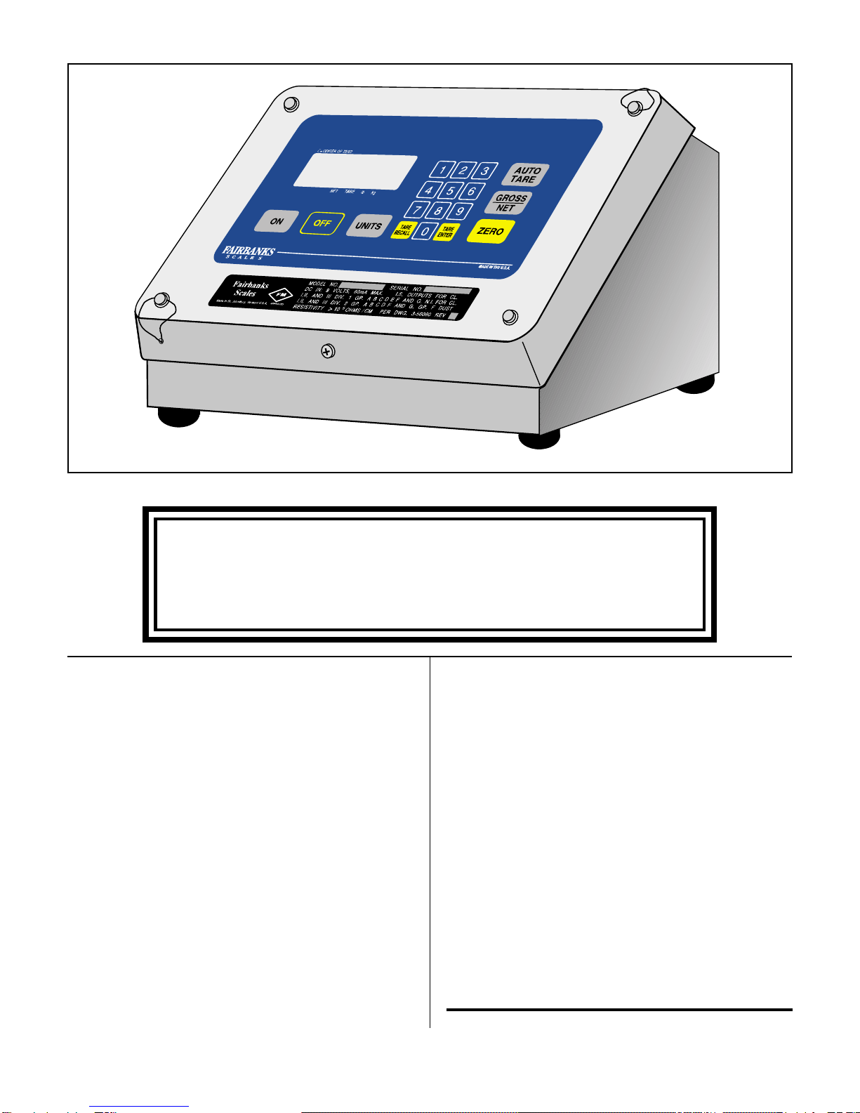
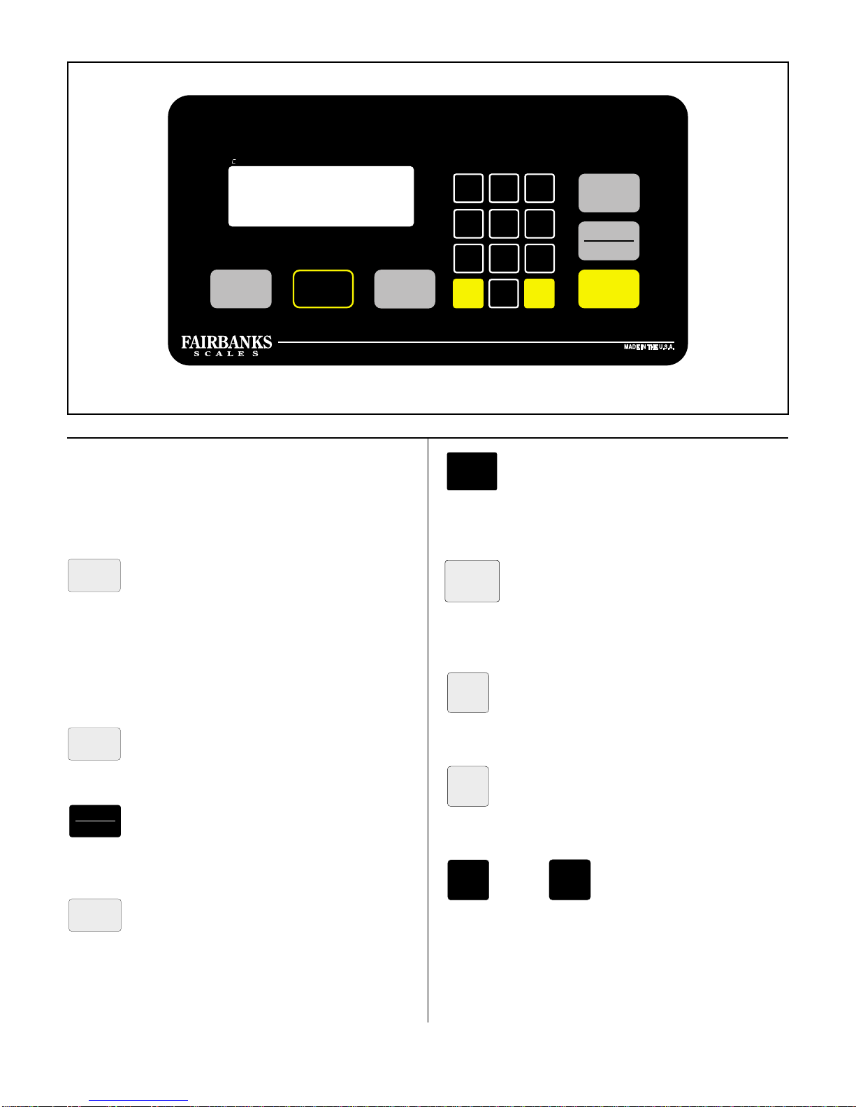
4.1 H90-3051 Front Panel Printer
Programming, Channel A
A. Channel A, Printers
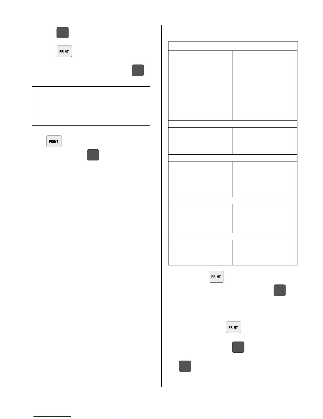
1. Data available to be printed:
Gross weight
Tare weight
Net weight
Time
Date
ID
Ticket Number
The above data items can be enabled or disabled for
printing. See Function Key Programming, Channel A.
2. The data will be transmitted over Channel A each time
the key is pressed if there is no motion on the
platform and a valid weight is displayed, ie. not out of
weighing range or in a non-weighing mode. “ACK”
legend will appear momentarily.
3. If the key is pressed during an inhibit condi-
tion, printing will not occur once the inhibiting condition
ends. The key will have to be pressed again.
B. Formatting Print Locations For Data
Strings To Be Printed
The locations are set by entering a line number and a
column number for the data item. A line number of 0 will
inhibit the printing of an item. Three types of printers are
provided for: a ticket printer, a form printer and a tape
printer.
A weight string consists of 6 or 7 weight characters, six
units characters and three legend characters as shown
below:
“39050 tonne GR”or “390.02 ton TA”or “1234.56 gal NT”
Each character within the quotation marks (spaces in-
cluded) will be printed. The six units characters and/or
the three legend characters may be suppressed.
For the remaining strings, typical outputs are given below:
“ 3:38 PM” or “17:56” time
“11–13–90” or “4– 4–91” date
“ 123” or “123456” or “ 0” identifier
“# ...123” or “# . ....7” ticket number
Tare and net weights may be printed only when the
instrument is in the NET weighing mode (net weight
displayed).
For all three printers, all characters in the weight strings
only may be printed with enlarged character sizes
(spaces included). Large characters are two columns
wide.
Ticket printer line spacing is set by the printer switches at
5, 6, 7 or 8 lines per inch. The form printer and the tape
printer have a fixed line spacing.
Both the ticket and tape printers have a 40 character width
with normal size characters. For large characters, the
width changes to 20 and 24 characters respectively.
Inverted printing is possible with the ticket printer - the
printer switch (inverted print switch - 7) must be set to the
closed position at all times.
Interface characteristics such as baud rate, number of
bits/char etc. are programmed as follows. At the comple-
tion of that sequence, the prompt “PtAL 0”is given.
Pushing the key will exit the program mode
whereas pushing the key will change the prompt
to “PtAL 1”. Pushing the key will now get the
operator into the formatting program (pushing the
key will change the prompt back to “PtAL 0”).
In addition to I/O Output Accessory A5805 being installed
in the instrument, Accessories 4901656, 5807, and 5808
must be installed and Channel A must be enabled at
Service Program Step 15.
1. Place the instrument into the weighing mode.
2. Press . “FunC”will be displayed.
3. Press and the display will show “CuSt”.
4. Press key and the display will show “Chan”.
ENTER
ENTER
7
PROG
8SJ4511

a. Press to return to the Weigh mode.
b. Press and “Chan A”is displayed.
5. With “Chan A”prompt displayed, press the key.
The display will show the Channel A baud rate.
NOTE
Do not set a baud rate of 19200 on one channel
and 38400 for another. Any other combination is
acceptable.
Set the Output Format as listed in the following chart.
The key toggles the operator through the
available options. The key saves the displayed
options and advances to the next parameter.
B. Programming Chart, Channel A
Baud Rate Options
Displayed Options
300
600
1200
2400 For Models K500, Okidata and
Eaton TicketPrinters
4800
9600
19200
38400 Stop Bits Options
Displayed Options
Stop 1 For Models K500, Okidata and
Eaton TicketPrinters
Stop 2 Parity Options
Displayed Options
EuEn
Odd For Models Okidata and Eaton
Ticket Printers
nonE For Model K500 Printer
Character Data Bits Options
Displayed Options
Char 7 (7 bit character) For Model Eaton Ticket Printer
Char 8 (8 bit character) For Models K500 and Okidata
Printers
Net Print Options
“gtn”When in Net mode Gross, Tare
and Net weight is printed
“nEt”When in Net mode Net weight
only is printed
Formatting: The key is used to scroll through the
options available at a particular step. The key
causes the current option to be registered and advances
the program to the next set of options.
After “gtn”or “nEt”has been entered, the display will show
“PtAL 0”. Pressing the key will toggle the dis-
play between “PtAL 1”and “PtAL 0”(“PtAL”stands for
“Print Alter”). Pushing the key will cause the in-
strument to revert to the normal weighing mode. Pushing
the key while the display shows “PtAL 1”will
advance the instrument to the formatting options.
ENTER
ENTER
ENTER
ENTER
ENTER
ENTER
9SJ4511

C. Formatting Options
The first option is the printer type. The table below gives
the options available for each printer type.The option that
appears as a prompt corresponds to the current option
selected.
PRINTERTYPES (1’st option)
“tiCPrt”“ForPrt”“taPE ”
“CHARACTER SIZE
“EnHAnC”“RE9uLr”
LEGEND SUPPRESSION
“LE9End”“noL9nd”
UNIT SUPPRESSION
“unit ”“nounit”
REVERSE PRINT (ticket printer only)
“Pt r2L”- prints right to left “Pt L2r”- prints left to right
FORM LENGTH (form printer only)
“LE 110”“LE 55”“LE 35”“LE n”
11 inches 5.5 inches 3.5 inches next print begins
after end of last print
The prompt “grL xx”appears and xx is the current value
of the line where the gross weight string will be printed.
To change the line number, use the numeric keys (“1”
through “9”and “0”) and push to register the
desired value. Decimal point entry is ignored (an entry of
13.5 is registered 135 e.g.). To exit the format program,
push only . To verify/change other line or column num-
bers, push the key. The complete list of
prompts/locations are listed in sequence below. The for-
mat program mode will automatically terminate after the
ticket column location is displayed and any non-numeric
key is activated.
“grL xx”gross line number
“grC xx”gross column number
“tAL xx”tare line number
“tAC xx”tare column number
“ntL xx”net line number
“ntC xx”net column number
“tiL xx”time line number
“tiC xx”time column number
“dAL xx”date line number
“dAC xx”date column number
“idL xx”identifier line number
“idC xx”identifier column number
“nuL xx”ticket line number
“nuC xx”ticket column number
D. Ticket Number
Ticket Number entry will be inhibited if Program Step 15
is not set to 1 or 3 (Chan A enabled).
Place the instrument in the weigh mode.
1. Press and keys. The “ENTER”and
“ACK”legends are lighted and the current ticket num-
ber is displayed.
2. To change the ticket number, use the numeric keys
through and then press . To retain
the displayed ticket number, press only . The
instrument will return to the weigh mode. Ticket num-
bers have a range from 0 to 999999.
A ticket number is only printed when a net weight is
printed and is incremented after each print. When the
instrument enters the “SLEEP”or “LO BAT”mode, the
next ticket number to be printed is entered into non-vola-
tile memory. This is the ONLY time the ticket number is
entered into non-volatile memory. If power is lost during
operations, the instrument will re-start with the last ticket
number in the non-volatile memory.
ENTER
ENTER
3
0 9
ENTER
ENTER
10 SJ4511

4.2 Output Formats
A. Typical Channel A, Printer Output
GROSS MODE
NET MODE
NETMODEwithNEGATIVENET
NET MODE, NEGATIVE GROSS and NET
GROSS MODE, NEGATIVE GROSS 2494
11 SJ4511

SECTION 5:
BATTERY PACK
5.1 Battery Pack Replacement
Disconnect the battery pack connector from the battery
port. Loosen the two thumb screws holding the dis-
charged battery pack in place and remove to a safe area
for recharging.
Replace with a freshly charged battery pack.
Press the key to restore the instrument to
operation.
5.2 Battery Pack Recharging
The Battery Pack Recharger is to be used to recharge the
Battery Pack. DO NOT USE FOR ANY OTHER PUR-
POSE.
The Battery Pack Recharger will partially recharge a fully
discharged battery pack in about 16 hours. To recharge
a battery pack:
1. Place the discharged battery pack on a flat surface
with the connector facing upward.
2. Insert the connector on the recharger into the connec-
tor on the battery pack.
3. Plug the recharger into a standard 110 VAC/60 Hz
outlet.
4. A minimum of 16 hours of charging time is required
before a battery pack can be reused. Full charge,
100% capacity, is attained between 36 and 48 hours
of charging time.
5. At temperatures above 84°F, battery packs can not be
recharged to 100% of their nominal capacity.
If a recharged battery pack is not required for immediate
use, it should be left on the charger to maintain maximum
charge. Leaving the battery pack on the charger will not
damage either component.
WARNING
Battery packs are to be recharged in
non-hazardous areas only.
ON
2653
FIGURE 5-1: BATTERY PACK RECHARGER
12 SJ4511

Model H90-3052DR Remote Display is NOT
for use with the H90-3052 Instrument.
Model H90-3052DR Remote Display will
work only with the H90-3051 ULPI with spe-
cial software.
13 SJ4511

APPENDIX I: CONTROL DRAWING
14 SJ4511
Table of contents